Windmill with axial generator on neodymium magnets
The strongest magnets with optimal parameters for use in generator design are neodymium magnets. They are somewhat more expensive than conventional ones, but they are many times superior and make it possible to create a powerful device in a relatively compact size.
There is no fundamental difference in the design. Neodymium magnets are manufactured in various form factors, allowing you to choose the most convenient option for yourself - thin oblong bars, tablet shape, cylinders, etc. if a metal rotor is used, then it is not necessary to glue the magnets; they themselves are attached to the base with force. All that remains is to fill them with epoxy to protect them from corrosion.
Key nodes
As mentioned, a wind generator can be made at home. It is necessary to prepare certain components for its reliable operation. These include:
- Blades. They can be made from different materials.
- Generator. You can also assemble it yourself or buy it ready-made.
- Tail zone. It is used to move the blades in the direction of the vector, providing the highest possible efficiency.
- Animator. Increases rotor rotation speed.
- Mast for fastening. It plays the role of an element on which all the specified nodes are fixed.
- Tension cables. Necessary for fixing the structure as a whole and protecting it from destruction under the influence of wind.
- Battery, inverter and charge controller. Contribute to the transformation, stabilization of energy and its accumulation.
Beginners should consider simple rotary wind generator circuits.
How to make a perpetual motion machine
Homemade generators with neodymium magnets are basically the same type in terms of their operating principle. The standard option is the axial type.
It is based on a car hub with brake discs. Such a base will become reliable and powerful.
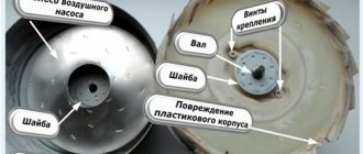
When deciding to use it, the hub should be completely disassembled and checked to see if there is enough lubrication, and if necessary, clean off the rust. Then the finished device will be pleasant to paint, and it will take on a “homey”, well-groomed appearance.
Magnets are glued to the rotor discs. The author of the design presented in the photo in the article took twenty pieces measuring 25*8 millimeters. A different number of poles can be used.
In a single-phase device, the number of poles must be equal to the number of magnets. In three-phase, the ratio of two to three or four to three must be observed. Magnets are placed with alternating poles. They must be precisely located. To do this, you can draw a template on paper, cut it out and accurately transfer it to the disk.
To avoid mixing up the poles, make notes with a marker. To do this, magnets are brought on one side: the one that attracts is designated with a “+” sign, and the one that repels is marked with a “-”. Magnets must attract, that is, those located opposite each other must have different poles.
Usually superglue or something similar is used, and after sticking it is filled with more epoxy resin to increase strength, after making “borders” so that it does not leak out.
Launch and performance evaluation
Even if the wind generator was manufactured according to all the rules, the wrong choice of location for the mast can play a cruel joke on the master. The element must stand vertically. It is better to place the generator along with the blades as high as possible - where strong winds “walk”. There should be no houses, any large buildings, or separately growing trees nearby. All this will block air flow. If any interference is detected, the generator should be placed at a certain distance from it.
After the installation starts working, you should connect a multimeter to the generator branch and check if there is voltage. The system can be considered ready for full operation. After this, it remains to find out what voltage will flow into the home and how this will happen.
Alternating single-phase and three-phase electric current
Electric current is the directed movement of electrically charged particles under the influence of an electric field (Appendix, Fig. 1). Such particles can be: in conductors - electrons, in electrolytes - ions (cations and anions). In the theory of electrical circuits, current is considered to be the directional movement of charge carriers in a conducting medium under the influence of an electric field. Conduction current is the amount of electricity flowing per unit time through the cross section of a conductor:
i=q/t,
where i is current (A), q = 1.6·109 is electron charge (C), t is time (s).
But this expression is valid only for DC circuits. For alternating current circuits, the so-called instantaneous current value is used, equal to the rate of change of charge over time:
i(t)= dq/dt.
An electric current is called alternating if it changes its direction over a certain time and continuously changes in magnitude. The value of alternating current varies according to a sinusoidal law (Appendix, Fig. 2):
i = Im sin (2πft),
Where; i – instantaneous current value, Im – amplitude or maximum current value, f – alternating current frequency value, t – time.
Alternating current is widely used due to the fact that alternating current electricity can be technically simply and economically converted from lower voltage energy to higher voltage energy and vice versa. This property of alternating current allows electricity to be transmitted through wires over long distances.
Industrial alternating electric current is obtained using electric generators, the operating principle of which is based on the law of electromagnetic induction. The rotation of the generator is carried out by some energy source.
Alternating single-phase electric current has the following main characteristics:
f – frequency of alternating current determines the number of cycles or periods per unit of time. The unit of measurement of alternating current frequency is Hertz (Hz) (1Hz = 10-3kHz = 10-6mHz);
Τ – period – time of one complete change of a variable value (if 1 period Τ occurs in 1 second, then frequency f = 1 Hz);
ω – angular velocity equal to – ω=2πf;
The current strength at individual moments when it changes along a sinusoid is called instantaneous current values. The largest instantaneous value of a single-phase alternating current when it changes along a sinusoid is called amplitude. Currently, the three-phase alternating current system is most widespread throughout the world. A three-phase system of electrical circuits is a system consisting of three circuits in which alternating electromotive forces of the same frequency act, shifted in phase relative to each other by 1/3 of the period (φ = 2π/3) (Appendix, Fig. 3) . Each individual circuit of such a system is briefly called its phase, and the system of three phase-shifted alternating currents in such circuits is simply called three-phase current.
Legality of installation
It is not prohibited to install installations with an output power of up to 75 kW on your own territory, and no approvals will be required (a fact enshrined in the Resolution of the Russian Cabinet of Ministers).
And if you need to install a powerful generator of an industrial or commercial type, then you will need special preparation related to the creation of the foundation and fencing of the site - and this is already considered capital construction.
It is recommended that you read local regulations regarding energy and utility services before installing VEL. Different regions may have their own rules.
It is important! Products with power up to a kilowatt are considered as household electrical products and do not require certification or any restrictions on use.
Generator selection
Making your own generator will require skills that not everyone has. For example, performing turning work. Therefore, it is necessary to consider the problem of purchasing a factory device that could be used on a wind turbine.
Types and features:
- Alternating current generators (asynchronous) are very easy to find and adapt to a wind generator. Cons: insufficient power; the unit will require modifications during installation.
- DC generators work great at low speeds and require almost no modifications. Disadvantages - it is difficult to find high-power generators.
- Asynchronous - it’s not a problem to buy a generator for little money, but such units are ineffective at high shaft rotation speeds, and internal resistance limits their power.
Generators are divided into two types according to the number of phases at the output. Single-phase generators are simple in design, but under high loads they vibrate strongly and can hum. Three-phase devices do not have these disadvantages, and in some modes they operate more efficiently.
Features of mast installation
Most often, the mast is made from metal blanks - either in the form of a complex frame (for large and powerful installations), or using one pipe (round/square cross-section), which is dug into the ground. In both cases, it is recommended to strengthen the mast with 3-4 guys made of metal rope.
Rotor creation process
The magnets should be positioned taking into account the alternation of poles, and as accurately as possible, but before you start sticking them, you need to either create a paper template or draw lines dividing the disk into sectors. To avoid mixing up the poles, we make marks on the magnets. The main thing is to fulfill the following requirement: those magnets that stand opposite each other must be turned with different poles, that is, attract each other.
The magnets are glued to the disks using super glue and filled in. You also need to make borders along the edges of the disks and in their center, either by wrapping tape or molding them from plasticine to prevent spreading.
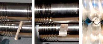
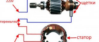
Modification of a car generator
Creating a permanent magnet rotor requires quite a serious intervention in the design. It is necessary to reduce the diameter by the thickness of the magnets plus the thickness of the steel sleeve, which is placed on the rotor to form a continuous magnetic flux and at the same time serves as a landing pad for the magnets. Some experts do without a sleeve, installing magnets directly on the rotor with a reduced diameter and fixing them with epoxy.
The manufacturing process requires the participation of production equipment. The rotor is clamped into the lathe and the layer is carefully removed so that the installed magnets rotate with minimal clearance, but quite freely. The magnets are installed on the rotor plates with alternating polarity.
Making a rotor from a hub and brake disc
The considered method applies to ready-made generators that require minor design changes. Such devices include car generators, which are often used by amateur designers as a basic device. Often, generators are assembled completely independently, without having a ready-made device.
In such cases, they act somewhat differently. The basis is a car hub with a brake disc. It is well-balanced, durable and adapted to certain types of loads. In addition, the size of the hub allows a large number of magnets to be placed around the circumference, allowing three-phase voltage to be obtained.
Magnets with alternating polarity are placed at a distance equidistant from the center. Obviously, the highest number can be set by gluing them as close to the outer edge as possible. The most accurate indicator will be the size of the magnets, which will determine the possibility of placement at a certain distance. The number of magnets must be even so that the rhythm of alternating poles during rotation does not break down.
Gluing magnets to the hub is done using any glue; the best option is epoxy resin, which is used to completely fill the magnets. This protects them from moisture or mechanical stress. Before pouring, it is recommended to make a plasticine rim along the edge of the hub to prevent the epoxy from flowing down from the hub.
The design of the generator on a car hub is most convenient when making a vertical windmill. It is noteworthy that a similar scheme can be used without a hub, on a disk cut from ordinary plywood. This design is much lighter, allows you to choose a convenient size, which makes it possible to create a sensitive and productive device.
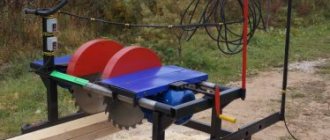
Rotary wind generator
The design of a rotor-type wind generator is the simplest, so it is the best option for self-production.
However, it is not suitable for powering a large house with a lot of electrical appliances. But, this is a good solution for the house and the area.
Electrical and technical parameters of the generator
The voltage is calculated using the formula:
Homemade generator
U=2*Ch*KP*KK*KV*MI*P, where:
- U – voltage in Volts;
- H – frequency of rotation of the generator rotor per second;
- KP – number of magnetic poles;
- КК – number of induction coils in the stator;
- KV – the number of turns of the conductor in one induction coil;
- MI is the magnetic induction in T, which is formed in a standard gap (2 mm);
- P – surface area of one neodymium magnet, in sq. m.
If simple coils are used, a magnetic induction of 0.5 Tesla is taken for calculation. When adding an electrical steel core, the value is increased to 0.7-0.9 T.
For your information. The formula is valid when connecting the windings in a triangle. If a three-phase generator is assembled using a star circuit, the resulting value is multiplied by a correction factor of 1.7.
After calculating the voltage, you need to find out the resistance in the windings. After this, it will be easy to determine the current and power. For a copper conductor, the resistivity is 0.0175 Ohm per mm2/meter. To calculate the total value, use the formula:
C= (US*D)/PP, where:
- C – resistance, in Ohm;
- US – resistivity of a certain material;
- D – conductor length in meters;
- PP – conductor cross-sectional area, mm sq.
To calculate the current, subtract the voltage of the battery connected for charging from the voltage of the magnetic generator at idle. The resulting value is divided by the resistance value calculated using the previous formula.
Increasing/decreasing the speed changes the current accordingly while keeping the voltage at the battery terminals constant. To calculate the performance of a wind turbine in different modes, use the standard formula:
P=I*U, where:
- P – power, Watt;
- I – current strength, Ampere;
- U – voltage, Volt.
Parts and Consumables
To manufacture a low-power (no higher than 1.5 kW) rotary wind generator, the following components will be required:
- 12-volt car alternator;
- 12-volt battery;
- converter from 12 V to 220 V, designed for power from 700 W to 1500 W;
- metal cylindrical container. You can use a regular bucket or a fairly large saucepan;
- relay for charging car batteries and a light bulb for charge control;
- 12V push-button switch;
- voltmeter;
- parts for threaded connections;
- wires with a cross section of 2.5 and 4 square;
- clamps for attaching the wind generator to the mast.
You will also need the following tools:
- shears for processing sheet metal (can be replaced with an angle grinder);
- roulette;
- marker;
- screwdriver;
- different wrenches;
- drill with drills;
- pliers and side cutters.
Manufacturing the stator of a three-phase alternating current generator
The generator stator is also made of 8 mm thick organic glass plates. In the plates, according to the markings, cavities are milled to accommodate 9 stator winding coils. The coils are wound with insulated copper wire D – 0.35 mm. Each coil holds the number of turns, according to the calculation data given above. The winding coils are glued into the grooves of the stator plates using sealant (Appendix, Fig. 13-15). Winding of all phase coils must be done in the same direction, marking the beginning and end of the winding. The connection of the coils of each phase is made according to the scheme: end - beginning. In total, three phase coils are placed on the stator plates, connected in series (Appendix, Fig. 16). The connection of all phase windings can be made in two ways: star and triangle (Appendix, Fig. 17 - 18). In our case, the connection is made by a star, including all stator plates. Current rectification is carried out by a three-phase rectifier made of semiconductor diodes (N4107) (Appendix, Fig. 18). The entire “sandwich” of the generator is assembled on a base made of organic glass. The stator plates are rigidly attached to the base with metal stands. The rotor plates are movably mounted on a bearing assembly from the disk drive motor. The axis of the bearing assembly passes through the entire generator and fastens the movable rotor plates (Appendix, Fig. 17).
Required tools and materials
To make a homemade windmill you will need the following parts:
- rotor with blades;
- gearbox for regulating the rotor speed;
- gel or alkaline battery for powering electrical appliances;
- inverter for current transformation;
- tail section;
- mast.
The rotor with blades can be made independently, while the remaining elements will probably have to be purchased or assembled from the necessary parts. In addition, to assemble a homemade windmill you will need the following tools and materials:
- wood saw;
- metal scissors;
- hot glue;
- soldering iron;
- drill.
Screws and bolts are required to connect the blades to the hub and to secure the metal pipe to the wood.
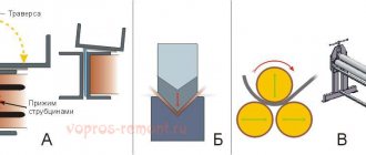
DIY wind generator blades
When making blades yourself, you should pay special attention to observing the shape of the products specified in the drawing. The blades can be wing or sail type. The second one is simpler to manufacture, but has low efficiency, which makes it ineffective in homemade wind generators of even medium size.
For the manufacture of homemade wind generator blades, the following materials are suitable:
- plastic;
- tree;
- aluminum;
- fiberglass;
- polyvinyl chloride
Design of the blade part of a wind generator
If you choose polyvinyl chloride, then PVC pipes with a diameter of 160 mm or more are perfect for creating blades. Plastic and wood are less wear-resistant materials that, under the influence of precipitation and strong winds, will become unusable in a few years. The best option is aluminum: it is durable and lightweight, resistant to tearing and creasing, and resistant to moisture and elevated temperatures.
Step-by-step manufacturing instructions
When all the drawings have been drawn up and the materials and tools have been prepared, you can begin to assemble the wind generator with your own hands, following the following procedure:
- Prepare the concrete foundation. The depth of the pit and the volume of concrete mixture are calculated based on the type of soil and climatic conditions. After pouring, the foundation needs several weeks to gain the required strength. Only after this can the mast be installed into it to a depth of 60-70 cm, securing it with guy ropes.
- Place the prepared blades in the pipe, secure them with screws and nuts on the bushing on which the engine will be installed.
- Place the diode bridge next to the engine and secure it with self-tapping screws. Connect the wire from the motor to the positive diode bridge, and the other wire to the negative bridge.
- Secure the motor shaft, put the bushing on it and tighten it tightly counterclockwise.
- Balance the base of the pipe with the motor and shaft attached to it and mark the balance point.
- Secure the base of the device with bolts.
A wind generator can last much longer if you paint not only the blades, but the base, shaft and engine cover. To turn on the installation you will need a set of wires, a charger, an ammeter and a battery.
Manufacturing a rotor for a three-phase alternating current generator
The rotor plates are made of organic glass 5 mm thick. Circles with a diameter of 95 mm were cut out of organic glass; according to the markings, 12 holes were drilled in them for neodymium magnets (D – 15 mm). Magnets with opposite poles were glued into the holes intended for them (Appendix sheet V, Fig. 12 - 13). Three such plates were made for the generator. The central plate, which is located between the stator plates, is made only of organic glass. Metal plates made of steel 1.5 mm thick are glued to the upper and lower rotor plates. Each plate contains 12 magnets, oriented along the poles.
Types of magnets
Permanent magnets are divided into 2 types:
- natural;
- artificial.
Natural
In nature, a natural permanent magnet is a fossil in the form of a fragment of iron ore. Magnetic rock (magnetite) has its own name in every nation. But in each name there is such a concept as “loving”, “attracting metal”. The name Magnitogorsk means the city's location next to mountain deposits of natural magnetite. For many decades, active mining of magnetic ore was carried out here. Today there is nothing left of Magnetic Mountain. This was the development and extraction of natural magnetite.
Until humanity achieved the proper level of scientific and technological progress, natural permanent magnets served for various fun and tricks.
Artificial
Artificial PMs are obtained by inducing an external magnetic field on various metals and their alloys. It was noticed that some materials retain the acquired field for a long time - they are called solid magnets. Materials that quickly lose the properties of permanent magnets are called soft magnets.
In factory production conditions, complex metal alloys are used. The structure of the Magnico alloy includes iron, nickel and cobalt. Alnico alloy contains aluminum instead of iron.
Products made from these alloys interact with powerful electromagnetic fields. As a result, quite powerful PMs are obtained.
Types and forms of PM
Advantages and disadvantages
The advantages of wind generators made using neodymium magnets include the following characteristics:
High efficiency of devices, achieved by minimizing friction losses;
- Long service life;
- No noise or vibration during operation;
- Reduced costs for installation and installation of equipment;
- Autonomy of operation, allowing operation without constant maintenance of the installation;
- Possibility of self-production.
The disadvantages of such devices include:
- Relatively high cost;
- Fragility. Under strong external influence (impact), a neodymium magnet can lose its properties;
- Low corrosion resistance, requiring special coating of neodymium magnets;
- Dependence on operating temperature – when exposed to high temperatures, neodymium magnets lose their properties.
Homemade windmill
Purchasing a wind generator is an expensive and not always completely effective undertaking.
Samples of commercially available wind turbines have a limited service life, low maintainability and high price. Purchasing such a kit is beyond the means of many potential users. The way out is to manufacture a wind generator yourself, which costs much less and allows you to get a device with high efficiency and productivity. A homemade windmill has high maintainability and, as a result, a long service life. Often, during operation, the design is modernized, improved and brought to the highest possible parameters, which cannot be done with factory kits.
Advantages
Devices can be purchased ready-made or made independently. Having purchased a wind generator, all that remains is to install it. All adjustments and alignments have already been completed, tests have been carried out under various climatic conditions.
Neodymium magnets, which are used instead of a gearbox and bearings, allow you to achieve the following results:
- friction is reduced and the service life of all parts is increased;
- vibration and noise of the device during operation disappears;
- the cost decreases;
- energy is saved;
- There is no need to regularly service the device.
A wind generator can be purchased with a built-in inverter that charges the battery, as well as a controller.
Connection process in the house
After installing an almost silent windmill with good power, you need to connect household appliances to it. When assembling such a device with your own hands, you should take care of purchasing an inverter converter with an efficiency of 99%. In this case, the losses due to the transition of direct current to alternating current will be the smallest, and there will be three nodes in the housing:
- Battery pack. Capable of storing energy generated by the device for future use.
- Charge controller. Provides longer battery life.
- Converter. Transforms direct current into alternating current.
You can install equipment to power lighting fixtures and household appliances that can operate on a voltage of 12-24 Volts. In this case, there is no need for an inverter converter. For appliances that allow you to cook food, it is better to use gas equipment powered by a cylinder.
Winding method for windmill stator coil
The coils should be wound with thicker wires if possible in order to reduce the resistance in them. This can be done on a mandrel or on a homemade machine.
In order to figure out what power potential the generator has, spin it with one coil, since, depending on how many neodymium magnets are installed and what their thickness is, this indicator may differ significantly. The measurements are carried out without load at the required number of revolutions. For example, if a generator at 200 rpm provides a voltage of 30 V, having a resistance of 3 ohms, then subtract 12 V (battery supply voltage) from 30 V and the resulting result is 18 divided by 3 (resistance in ohms) we get 6 ( current in amperes), which will go from the wind generator to charge the battery. However, as practice shows, due to losses in the wires and diode bridge, the actual indicator that the magnetic axial generator will produce will be less.
The thickness of the stator should be the same as the magnets. The form for it is usually plywood; for strength, fiberglass is placed under the coils and on top of them, and the whole thing is filled with epoxy resin. In order to prevent the resin from sticking to the mold, the latter is lubricated with any fat or adhesive tape is used. The wires are first brought out and fastened together, the ends of each phase are then connected with a triangle or an asterisk.
Source of electricity
Tariffs for electricity services increase at least once a year, often several times. This hits the pockets of citizens whose wages are not growing as rapidly. Home craftsmen used to resort to a simple, but rather unsafe and illegal way to save on electricity. They attached a neodymium magnet to the surface of the flow meter, after which it suspended the operation of the meter.
If this scheme initially worked smoothly, then later problems arose with it. This was explained by several reasons:
- Inspectors began to visit homes more often and conduct unscheduled inspections.
- Special stickers began to be glued to the meters, under the influence of which the magnetic fields began to darken. Accordingly, identifying such an intruder was not a problem.
- New meters began to be produced that were not susceptible to magnetic fields. Instead of standard models, electronic units appeared.
All this pushed people to search for alternative sources of electricity, for example, wind generators. If a person lives in areas where winds regularly blow, such devices become a “lifesaver” for him. The device uses wind power to generate energy.
The body is equipped with blades that drive the rotors. The electricity obtained in this way is transformed into direct current. In the future, it passes to consumers or accumulates in the battery.
A homemade wind generator can act as the main or additional source of energy. As an auxiliary device, it can heat water in a boiler or power household lamps, while all other electronics operate from the main network. It is also possible to operate such generators as the main source where houses are not connected to electricity. Here the devices are powered:
- lamps and chandeliers;
- heating equipment;
- consumer electronics.
A wind power plant is capable of powering low-voltage and classical appliances. The first ones operate on a voltage of 12-24 Volts, and the wind generator is capable of providing power at 220 Volts. It is manufactured according to a circuit using inverter converters. Electricity is stored in its battery. There are modifications for 12-36 Volts. They have a simpler design. They use standard battery charge controllers. To ensure heating of your home, it is enough to make wind generators with your own hands at 220 V. 4 kW is the power that their engine will provide.
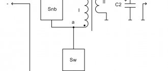
How the devices work
The main problem of the design was considered to be the return of rotating parts to their original position without significant loss of torque. This problem was solved by using a copper conductor through which an electric current was passed, causing attraction. When the current was turned off, the attraction stopped. Thus, devices of this type used periodic on-off switching.
The increased current creates an increased attractive force, which, in turn, is involved in the generation of current passing through the copper conductor. As a result of cyclic actions, the device, in addition to performing mechanical work, begins to produce electric current, that is, perform the functions of a generator.
NUMBER OF PHASES
When designing generators, preference is almost always given to a three-phase design - it is complex, but it gives a constant current output, does not produce noticeable vibrations, and the current power is also stable due to phase compensation. But still, the main advantage of the three-phase design is the almost complete absence of vibration.
A wind generator of any type is always subject to high load and any vibration is a potential threat. In addition to everything, it should be noted that vibration creates additional noise, so it is better to give preference to a three-phase generator.
The nature of magnetism
The demonstration of the properties of a magnet in attracting metal objects to itself raises the question among people: what are permanent magnets? What is the nature of such a phenomenon as the occurrence of traction of metal objects towards magnetite?
The first explanation of the nature of magnetism was given in his hypothesis by the great scientist Ampere. Electric currents of varying degrees of strength flow in any matter. Otherwise they are called Ampere currents. Electrons, rotating around their own axis, also revolve around the nucleus of the atom. Thanks to this, elementary magnetic fields arise, which, interacting with each other, form the general field of matter.
In potential magnetites, in the absence of external influence, the fields of the atomic lattice elements are randomly oriented. An external magnetic field “arranges” the microfields of the material structure in a strictly defined direction. The potentials of opposite ends of magnetite repel each other. If you bring the identical poles of two strip PMs closer, then a person’s hands will feel resistance to movement. Different poles will tend to each other.
When steel or an iron alloy is placed in an external magnetic field, the internal fields of the metal are strictly oriented in one direction. As a result, the material acquires the properties of a permanent magnet (PM).
How to make a disk generator correctly instructions
Hello, people often write to me about how best to make an axial disk generator, how many magnets there should be and how many coils. They ask what wire the coils should be wound with and how many turns. They ask about the ratio of magnets to coils, and how to connect the coils to each other. I will try to answer these questions, accompanying them with drawings.
General rules for constructing an axial generator
1. The distance between the magnets in a circle on the disks should be equal to their width, but the denser the better, ideally if the magnets are almost close to each other. Below I described in more detail, if you can’t decide, make the distance equal to the width of the magnets, it will work like everyone else. 2. Round magnets, square or rectangular, it doesn’t really matter, this will then be reflected in the shape of the coils. For the first option, round magnets and coils are simpler. 3.The thickness of the disks should be equal to the thickness of the magnets, or slightly thinner. 4. The number of turns in the coils for a 12V battery is 60 turns, for a 24V VCB is 90 turns. 5. Thickness of the stator according to the thickness of the magnets. 6. The ratio of coils to magnets is 4:3, for 9 coils there are 12 magnets, for 12 coils there are 16 magnets. Single-phase generators are not made because there will be strong vibration of the generator during operation.
Conclusions and additional information
Using a gearbox and careful calculation of the blades, you can create a low-speed, low-noise, low-speed generator using neodymium magnets. Modern electronic components and corresponding circuitry will help create an inverter with high efficiency. New battery models perform their functions flawlessly, without routine maintenance, and retain their useful functions after hundreds of recharge cycles.
Wind generators with a vertical axis of rotor rotation
To get acquainted with existing installations, you can see the implemented projects of Sergei Savchenko, Alexander Sedov, Valery Yalovenko, Victor Burlak. Their ideas can be transformed taking into account personal capabilities and preferences. It’s easy to simplify calculations using specialized calculator programs that can be quickly found on the Internet. In any case, the magnetic generator should be considered in conjunction with other parts of the off-grid power supply system to ensure good coordination.
What should you pay attention to?
- When choosing a wind generator for home use, you need to pay attention to the wind utilization factor and, of course, the most important thing is power. In good options for wind generators for home, the coefficient reaches up to 45%, which is very productive. The power on home appliances starts from 300 W to 10 kW (the second indicator is enough to ensure that all electrical appliances in your house work).
- A very important aspect when choosing a windmill for your home is its speed. In standard versions it ranges from 5 to 7 units. For example, if you chose a windmill with a speed unit of “5,” this means that with a wind of 10 meters per second, your propeller will spin at a speed 5 times faster, that is, 50 meters per second.
Both standard wind generators with a horizontal axis of rotation and vertically oriented ones are created; their screw represents not a vertical, but a horizontal impeller. When choosing a second device, you do not need to focus on the direction of the wind, however, they are more difficult to manufacture, install and operate, so they are not very popular.
What does work efficiency depend on:
- Designs of a specific unit. A lot depends on this, because each windmill has its own assembly features, so each of them will differ in performance. Much depends on the size of the windmill itself and the lightness of its blades. The generator itself (the heart of the entire structure) also plays an important role.
- Weather conditions of the area where the wind turbine is installed. As stated earlier, there is no point in installing this thing in a non-windy area. If you install it in low wind conditions, you will not get any benefit from it.
Conclusions and additional information
Using a gearbox and careful calculation of the blades, you can create a low-speed, low-noise, low-speed generator using neodymium magnets. Modern electronic components and corresponding circuitry will help create an inverter with high efficiency. New battery models perform their functions flawlessly, without routine maintenance, and retain their useful functions after hundreds of recharge cycles.
To get acquainted with existing installations, you can see the implemented projects of Sergei Savchenko, Alexander Sedov, Valery Yalovenko, Victor Burlak. Their ideas can be transformed taking into account personal capabilities and preferences. It’s easy to simplify calculations using specialized calculator programs that can be quickly found on the Internet. In any case, the magnetic generator should be considered in conjunction with other parts of the off-grid power supply system to ensure good coordination.
Wind generator in a home construction kit
So, we can assume that a generator has been selected - the main part of the wind energy regeneration system. It remains to add:
- three blade propeller,
- weather vane system,
- metal mast,
- battery charge controller.
It is advisable, but not necessary, to follow the production sequence of all remaining parts of the wind generator. Consistency is the order that is necessary in any business to achieve results. Obviously: ready-made kits provide significant assistance in the construction of an energy machine: