Electrical power, designated in the diagrams by the letter P, is a physical quantity that characterizes the rate of conversion or transmission of electricity. The standard concept is the effort to move an electric charge along a route from point F1 to point F2.
The electrical power of a device is a key parameter that determines the potential for its operation in the electrical network. Used to calculate circuits and operating modes of equipment to ensure the safety of electrical networks. The greater the power of the device, the faster they perform the desired action.
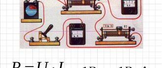
Formulas for calculating voltage, current, power, resistance Source amperof.ru
Electrical current through voltage and current
Since the potential difference calculated by the formula (F1-F2) determines the voltage (U), it is easy to conclude that the relationship established by Ohm’s law cannot be used. Electrical power (P) is also qualified by the current strength (I) on a specific section of the line. Final expression: P = U x I.
What is the load determined in terms of current and resistance?
Through a simple conversion, the electrical energy consumption is determined using the following formula: P = I2 x R. This shows the dependence of the power on the nominal value of the resistor connected to the line of the network element. For a complete circuit, the source resistance (internal) and the conductance of the connection point are indicated.
Direct current measurement
The methods of that group are characterized by higher accuracy due to the fact that they are based on direct measurement of current. There are two devices for performing this procedure at home.
Metering with current clamps
The most convenient to use are current clamps that do not require breaking the controlled circuit. Designed as a hand-held device with a measuring unit based on a toroidal core. To measure the current, the assembly is opened in the manner of pincer sponges, and then closed to cover the wire, Figure 3. The effective value of the current is determined by the change in the magnetic field, which is recorded by the Hall sensor.
Measurement with a tester
The second method is based on the use of a tester, which is switched to ammeter mode and connected to an open circuit. The difficulties of implementing this procedure using simple means make it little popular in practice. We also cannot discount the fact that some tester models do not have current protection and fail (burn out) if the range is incorrectly selected (current overload).
What is it and how to calculate the load
Electric current load is a quantity characterizing its properties. Shows how much energy is consumed by electrical appliances. The current power is measured using a special device - a wattmeter.
If you connect a meter in series, you can check the current strength. When connecting in parallel, the voltage is determined. The amount of circuit consumption is calculated using the formulas: P = I x U or P = U2/ R = I2 x R.
The electrical load is equal to the voltage across the consumer multiplied by the amount of current flowing through it.
P = U x I
The formula indicates which measurements determine this parameter. If the load is active, it is measured in Watts, the reactive unit of electrical power is VA.
Reactive unit of electrical power - VA Source infourok.ru
Load measurement methods
You can find out the power of the device by referring to its instructions or passport, and if not, look at the nameplate attached to the body. If manufacturer data is not available, then other methods are available to determine the energy efficiency of the equipment. The main one is to measure the load using a wattmeter (a device for recording electrical power).
According to their purpose, they are divided into 3 classes: direct current and low-frequency (LF), optical and high-impulse. The latter belong to the radio range and are divided into 2 types: those included in the line break (passing power) and those mounted at the end point of the route as a matched (absorbed) load. According to the method of conveying information to the operator, a distinction is made between digital and analogue devices - pointer-type and recorder-type. Brief characteristics of some meters:
- LF wattmeters are used in single- and three-phase industrial frequency networks. This category also includes varmeters - devices for determining reactive power. Analog meters are represented by models D5071, D8002, Ts301. Digital combine the capabilities of recording not only the Wa component, but also the Wр component. The final value is displayed on the display and external devices - a printer or electronic information storage devices. Devices of this type are ShchV02, SR3010, MI2010A.
- Wattmeters of transmitted radio power. The sensors in the meter are current and voltage transformers. For ultrahigh frequencies - thermistor, galvanomagnetic and thermoelectric converters. Samples - NAS, M2−32, M2−23.
- Wattmeters for measuring the absorbed load of radio spectrum pulses - they use the power reflectance coefficient. There are several types of devices: thermistor M3−28 and M3−22A, calorimetric MK3−68, MK3−70, M3−13, thermoelectric wattmeters M3−93, M3−56, M3−51 and with a peak detector M3−3A, M3− 5A.
- Optical meters - OM3−65, OMK3−69.
In addition to the help of special devices, power is determined by applying a calculation formula: an ammeter is connected to the break in one of the supply wires, the current and voltage of the network are determined. Multiplying the quantities will give the desired result.
How to determine the maximum current load
The useful power shows the maximum value in a situation where the load resistance R is compared with the same parameter inside the source - r.
R = r.
P max = E2 / 4r, where E is the driving force of the current source.
To calculate the maximum current load for an electrical device, you need to know the rated load parameter and the AC input voltage. The technical data sheet of the device, manual or emblem contains the first indicator.
For example, when the appliance rating (P) is 12 W, the maximum current consumption at AC voltage will be for:
- 120 V – I = 12/120 = 0.100 A or 100 mA.
- 220 V – I = 12 / 220 = 0.055A or 55 mA.
If necessary, the amount of electricity consumed is expressed through a complex value. For this purpose, basic relationships are used, impedance is used instead of resistance.
Electrical Appliances Parameters
Every modern apartment must be equipped with electrical appliances. To connect them to the network, it is necessary to draw up a schematic diagram where the loads connected to individual lines will be distributed in coordination with each other. It is necessary to build in a circuit breaker based on the PUE to prevent emergency situations.
First, the electrical wiring parameters are clarified. Then they are checked according to the group diagram for connecting to the network of household electrical appliances.
Standard characteristics of electrical power consumption (W):
- desktop computer – 170-1,250;
- LCD TV – 120 – 265;
- laptop – 40-280;
- air conditioning – 1,200 – 2,500;
- iron – 450-1850.
To protect the network, you need an automatic machine; we choose it taking into account all the significant factors.
Automatic switch for protecting the electrical network Source vmasshtabe.ru
It is important to pay attention to loads that have increased reactive energy parameters.
The process of measuring active and reactive power
Induction or electronic meters measure the active power of an alternating voltage circuit. They are connected using the same circuits as wattmeters. Reactive energy in single-phase consumers is not metered in our country. It is metered in three-phase circuits of large industrial enterprises that consume large volumes of electricity. Active energy meters are marked SA, reactive SR. Electronic electricity meters are also widely used.
What is it measured in?
The unit of measurement of electrical power is W for Russia. By international standards - W. This is the energy provided per unit of time. One W is equal to a joule per second (J/s). Moreover, a joule is a unit of electrical power, a second is a unit of time.
For small values, multiple prefixes are used: “milli-”, “micro-”, for large values - “mega-”. For example: 5,800 W = 5.8 kilowatts = 5.8 kW.
When you multiply 1 Kilowatt by 1 hour, you get a Kilowatt-hour (kW x h). This is a unit of measurement of the amount of electricity provided to subscribers. It is used by energy enterprises that own the appropriate equipment (generators and transformer substations). They generate and convert the produced electricity, which is then distributed to consumers.
In the same way, the energy capacity of batteries is measured in units of ampere hours (Ah). Portable types of energy storage batteries are measured in milliampere hours (mAh).
The energy in batteries is measured in milliamp hours (mAh). Source listtopa.ru
For the unit of measurement Watt, according to international standards, the letter designation W is allocated after James Watt. He was the first to use the term “horsepower,” which today is an obsolete unit of the W parameter.
Energy conversion indicators:
- horsepower (HP) - 746 W;
- kilo Watts (kW) – 1×1000 W;
- megawatts (MW) −1×1000000 W;
- gigawatt (GW) – 1×1000000000 W.
Today, "horsepower" is used to indicate the second measure of engine power in vehicles.
What determines the load of electric current?
Existing electrical wiring lines experience resistance during the movement of electrons, which characterizes voltage loss. Circuits where an alternating current source is present have one feature - the key role here is played by a sinusoidal oscillation of electrical indicators.
Sinusoidal oscillation of electrical indicators. Source urpsvet.ru
The following information will allow you to select the best calculation method based on actual network conditions.
Instantaneous electrical power: calculating the value
This indicator establishes the instantaneous values of the measured data. The key definition is considered taking into account the fact that a single simple charge (q) moves in a certain time Δt. To perform a specific action, the energy of electric current PF1-F2 = U/ Δt or (U/ Δt) x q = U x (q/ Δt) is expended. The formula takes into account the movement of q over the period Δt. Since the current, according to the classical definition, is equal to the charge moving from F1 to F2 (I = q/ Δt), the final expression is derived: PF1-F2 = U x I.
Conditionally assuming that the time period is very short, we obtain the instantaneous power for part of the electrical circuit P(t) = U(t) x I(t). The same conclusions can be drawn taking into account the corresponding resistance parameter: P (t) = (I (t))2 x R = (U(t))2/ R.
Electrical power: DC circuit
The previously mentioned formulas are shown without correction factors. They are used to calculate a circuit connected to a direct current source. Using an ordinary device - a multimeter, with the switch in the correct position, the resistance of the load connected to the network is set.
With its help, the load resistance is set. Source hammer-shop.ru
Electrical power: AC circuit
For such lines, it is unacceptable to use formulas that determine instantaneous parameters, since the final indicator changes from a minimum value to a maximum value with the network frequency. A typical single-phase 220 V network is characterized by a 50 Hz sinusoidal signal. It is allowed to use the simple formula P = U x I when connecting devices with resistive parameters:
- Heating elements of washing machines;
- spirals of infrared heaters;
- incandescent light bulbs.
Using this formula, the load is set.
Energy can be of two types: reactive and active.
Active is the true electrical power that produces real work in the load, W shows this parameter. It converts energy into mechanical, thermal and other forms.
If you turn on a powerful unit or capacitor, the voltage inside the network drops. Such loads create an oscillating circuit that receives energy from the power source. In this situation, only P act components perform useful functions. The active indicator is calculated in the following way:
- U x I – direct current (alternating current with a resistive load);
- U x I x cos fi – for a single-phase 220 V line;
- U x √3 x cos fi = U x 1.7321 x cos fi – 3-phase network, U x √3 x 380V.
There are other types of energy, but more on that later.
Active and passive energy Source ppt-online.org
Reactive power
This indicator shows the loads that are created in devices due to fluctuations in the energy of the electromagnetic field.
Reactive power, regardless of the absence of useful work, must be taken into account to correctly evaluate key network data. Cables and wires, when current passes through them in any direction, heat up. This happens quite cyclically. Energy effects at high intensity:
- damage cable cores and protective insulation;
- contribute to the occurrence of a short circuit;
- destroy the windings of transformers and drives.
Reactive power is expressed as VA (volt-amperes) and is calculated by multiplying the voltage by the current and the shear angle:
P r = U x I x sin fi.
When connecting a load with capacitive parameters, the value becomes negative, when inductive it becomes positive. Since the characteristics of the magnetic field change, the unit of measurement for reactive power is VA.
If the parameters of total electrical power are shown as vectors, a triangle appears. The length of its sides will be equal to the amount of electricity consumed by a particular component. The angle between the apparent power (Pap) and the active power (ϕ) is used for calculations. The total value is determined by the expression: P total = √((P act)2 + (P react)2).
What is electric power
When describing electrical power in a broad sense, we are most often talking about the energy or force with which some object or action is endowed. For example, it can be defined for an explosion or a mechanism, such as an engine. This parameter is associated with force and depends on it, which is why these phenomena are often confused.
The difference is that force affects physical actions, that is, work is performed. If it is done in the specified time, then through these two parameters the power value can be calculated.
In the case of electricity, there are two types:
- Active - turns into energy of heat, light, mechanical action, etc. It is measured in watts and calculated by the formula 1 W = 1 V x 1A. But in practice, this indicator is most often expressed in kilowatts and megawatts.
- Reactive – load arising due to oscillations within the electromagnetic field. The unit of measurement is volt-amperes (VA), they are calculated as Q=U x I x sin angle. The latter means a phase change between current and voltage reduction.
In practice, the differences between both types are best seen using the example of heating elements and electric motors. Heating elements are assembled from a material with high resistance, so they convert all the electricity received into heat. The electric motor has parts that have inductance, that is, part of the current returns to the network and can negatively affect it, creating overloads.
What is power in electricity
Voltage is the work done to move a unit of charge. Current is the number of coulombs moved in 1 second. When multiplying the first parameter by the second, the total amount of work done in 1 second is obtained.
The strength of electricity is a numerical current meter that characterizes its energy qualities. The power indicator equally depends on voltage and current strength. How is current power measured? To measure this parameter, a Wattmeter is used; the unit of measurement is designated in the same way - W (Watt).
By using the dependence of the power parameter on current and voltage, specialists can transmit electricity over long distances. For these purposes, energy is converted at step-down and step-up transformer substations (transformer substations).
Current power through the coil
Let alternating voltage be applied to the coil. The current through the coil lags in phase from the voltage by:
For instantaneous power we get:
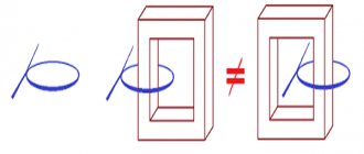
Again the average power is zero. The reasons for this are, in general, the same as in the case of a capacitor. Let's look at the graphs of voltage and current through the coil over a period (Fig. 5).
Rice. 5. Voltage on the coil and current through it
We see that during the second and fourth quarters of the period, energy enters the coil from the external circuit. In fact, voltage and current have the same signs, the current increases in magnitude; To create a current, the external electric field does work against the vortex electric field, and this work goes to increase the energy of the magnetic field of the coil.
In the first and third quarters of the period, the voltage and current have different signs: the coil returns energy to the circuit. The vortex electric field, which maintains a decreasing current, moves charges against the external electric field and thereby does positive work. How is this work accomplished? Due to the energy previously accumulated in the coil.
Thus, the energy stored in the coil during one quarter of the period is completely returned to the circuit during the next quarter. Therefore, the average power consumed by the coil is zero.
Electrical power and inactive power
Equipment certificates contain active load - power factor, which is an important characteristic. It shows how efficiently a household appliance consumes electricity.
Fig.8
This is a number from −1 to 1, it is never equal to one. This coefficient depends on the type of load: C, L or R. The first 2 negatively affect PF = cos φ of the system. If its parameter is large, the current consumed by the devices increases. Many power loads are inductive, causing the current to lag behind the voltage.
Inactive energy arises in electrical AC circuits of alternating current networks. It is calculated simply: the square root of the sum (Pa2 + Pr2). If the reactive load is zero, then the passive load is equal to the modulus |Pa|.
The presence of nonlinear current distortions in electrical networks is caused by non-compliance with the direction that occurs between U/I, since the energy has a pulsed nature. In nonlinear modes, the apparent current power (EP) increases. Such a load is inactive and consumes Pr and current distortion energy. The unit of measurement is the same as regular power W.
Total maximum power and maximum current
Active and reactive maximum powers
Calculation of maximum power.
Calculation of replacement power.
Shift power takes into account the amount of power used during the busiest shift.
For operating industrial enterprises, active and reactive power
Рcm=Wa/Tcm Qcv= Wр/Tcm
where Wa is active energy, kWh; Tcm is the duration of operation of electrical receivers per shift, h; Wр – reactive energy kvar*h
For newly designed industrial enterprises, the active and reactive power of each single electrical receiver
Rcm=RnomKi
where Ki is the utilization coefficient of the electrical receiver.
Maximum power is the maximum power consumed by a site, workshop, or plant during the first shift in 30 minutes. if in 30 minutes the wires can withstand the maximum load and do not overheat, then the selected cross-section is sufficient for these consumers to receive a sufficient amount of electricity.
Рmax = Рcm Qmax = Qcm
Smax=
When calculating and studying power electrical loads, design coefficients are used that characterize the operating modes of electrical receivers, energy consumption, power, time and load schedules.
The utilization coefficient Ki of one or the average coefficient of a group Kis of electrical receivers characterizes the use of active power and is the ratio of the average active power Рcm of one or a group of receivers for the busiest shift to the rated power Рnom
Ki=Rcm/Rnom.
Switching factor is the ratio of the operating time of the electrical receiver Tr and the cycle time Tc:
Kv = Tr/Tc
If the cycle coefficient is less than 10 minutes, then we introduce a restart.
Turning on the load is the ratio of the actual consumed active power RF to the rated active power of the electrical receiver:
Kz = Rf / Rnom
For electrical receivers operating in repeated, short-term, long-term and automatic operating modes.
Demand factor is the ratio of the maximum active power Ra of one or a group of electrical receivers to the rated power Рnom of the same group:
Ks= Pmax/Pnom
Maximum coefficient - the ratio of the calculated maximum active load power of a group of electrical receivers to the average load power for the busiest shift:
Kmak = Rmak/Rsm
The value of Kmsax>1 is determined from tables or graphs depending on the value of the average utilization factor Ki.s and the effective number ne of the group of electrical receivers.
The effective number is the number of electrical receivers of the same power, homogeneous in operating mode, which gives the same value of the calculated maximum Pmax as a group of electrical receivers of different power and operating mode. Since the effective number is determined for a group of electrical receivers connected to power panels or a substation switchboard, it is necessary to take into account the indicator of the power assembly - the number m, equal to the ratio of the rated power of the largest electrical receiver Rnom max1 to the rated power of the smallest Rnom min1:
m=Pnommax1/Pnom min1
the number ne is determined by the following indicators: the number of electrical receivers n connected to the power source; power assembly indicator m average utilization factor Ki, with rated active power Pn of an individual electrical receiver.
When n>5; Kis>0.2; m> 3 Pnom =const ne=n
At n>5 Kis<0.2 m>3 Pnom≠const
Ne=n*en
n*е=f(n*;P*)
- relative effective number
n*=n'/n
- relative number of electrical receivers with the largest power; n - number of receivers with unit power greater than or equal to Pn max 1
P*=P n/Pnom
Determination of design power loads using the maximum coefficient method.
The basis for determining such loads from a group of electrical receivers, taking into account the maximum coefficient, is the method of ordered diagrams, which makes it possible to determine the calculated maximum load based on the rated power and characteristics of electrical receivers:
Rmak = KmaxRsm
According to design practice:
Q max=1.1Qcm
If in a group of electrical receivers a workshop or enterprise has electrical receivers operating with leading current, then the reactive powers Qcm are taken with a minus sign and subtracted from the total reactive power.
After determining Pmax and Qm, how can you calculate the total power:
2
Estimated maximum current for AC power consumers: