A gasoline generator or its diesel analogue, at their low cost, is the most suitable source of emergency power supply for a private home or cottage. Such installations are easy to transport and operate . The electrical installation of a gas generator, as well as its selection, requires a responsible approach. Incorrect connections can cause damage to household appliances or short-circuit wires in the house, not to mention it poses a danger to life. But if you know how to connect a gas generator to the home network correctly, you can restore the operation of electrical appliances quickly and safely.
How can you not do it?
When connecting a gas generator to the house, you cannot connect it to any nearby outlet without turning off the circuit breakers on the switchboard in advance.
The power of the generator can be much greater than the capacity of the outlet (usually the latter is designed for 3500 W). The result is a short circuit due to exceeding the maximum load, and a fire.
If at the same time you do not turn off the main line circuit breakers, then supplying energy to the network will lead to a breakdown of the generator.
Connecting home power through an outlet is only allowed for low-power (up to 4 kW) installations. But even in this case, it is better to connect electrical appliances to the generator via an extension cord. For powerful stations it is necessary to use an autostart system - AVR or a reversing switch.
“Emergency” connection methods and their disadvantages
Typically, “fire” methods are used in cases where for some reason it is impossible to use the generator directly - you need to connect it to your home network urgently, and there is no time to install a separate connection circuit.
What distinguishes a specialist from an ordinary person, among other things, is knowledge of the reasons for prohibitions - this is what allows one to bypass them at the right moments: to do something not according to the rules, but to get the desired result. Just don’t forget the platitudes - electricity does not forgive mistakes, which means you need to calculate your actions several steps ahead in order to eliminate all possible mishaps.
Connection via socket
The most common “fire” way to connect a generator to a house is to simply plug it into an outlet, for which you buy or make your own “carrying” with plugs at the ends.
This method is strongly discouraged, but the simplicity of its use has won over many owners of small and medium power generators time and time again.
The principle of using such a connection becomes clear if you look at a standard home wiring diagram. Indeed, if you connect a current source to one of the sockets, voltage will appear in all parts of the circuit.
1. Introductory machine. 2. Electricity meter. 3. Generator. 4. Distribution machine. 5. Sockets.
There are not so many disadvantages of this method, but you need to remember about them so as not to damage the generator.
1. Wire overload.
You can ignore this point if you use a generator with a power of up to 3 kW. Socket lines are standardly connected with a wire with a cross-section of 2.5 mm², and the sockets themselves are designed for a maximum current of 16 Amps. According to the table of the ratio of cable cross-section to the current strength that they can pass, even aluminum wires (which are already prohibited for installation) of this cross-section can easily withstand power up to 3.5 kW.
| Cable core cross-section, mm2 | Cable core diameter, mm | Copper core | Aluminum core | ||||
| Current, A | Power, kW at network voltage 220 V | Power, kW at network voltage 380 V | Current, A | Power, kW at network voltage 220 V | Power, kW at network voltage 380 V | ||
| 1 | 1,12 | 14 | 3,0 | 5,3 | — | — | — |
| 1,5 | 1,38 | 15 | 3,3 | 5,7 | — | — | — |
| 2,0 | 1,59 | 19 | 4,1 | 7,2 | 14 | 3,0 | 5,3 |
| 2,5 | 1,78 | 21 | 4,6 | 7,9 | 16 | 3,5 | 6,0 |
| 4,0 | 2,26 | 27 | 5,9 | 10,0 | 21 | 4,6 | 7,9 |
| 6,0 | 2,76 | 34 | 7,7 | 12,0 | 26 | 5,7 | 9,8 |
| 10,0 | 3,57 | 50 | 11,0 | 19,0 | 38 | 8,3 | 14,0 |
| 16,0 | 4,51 | 80 | 17,0 | 30,0 | 55 | 12,0 | 20,0 |
| 25,0 | 5,64 | 100 | 22,0 | 38,0 | 65 | 14,0 | 24,0 |
| 35,0 | 6,68 | 135 | 29,0 | 51,0 | 75 | 16,0 | 28,0 |
Using the formula for finding power P=I*U, you can determine the maximum current supplied by the generator. If its power is 3 kW and the voltage is 220 Volts, then I = 3000 / 220 ≈ 13.65 Amperes, i.e. the safety margin of even a standard outlet should be more than enough (of course, if these are not outdated, still Soviet models, designed for a maximum at 6.3 or 10 Amps).
Another thing is generators of higher power - for them all calculations must be carried out separately. True, they are all usually permanently connected and the urgent need to “throw” them through an outlet can only arise in the event of a wiring fault. This is where you need to know for sure what is being violated and whether it can be done.
2. Human factor.
Before turning on the backup generator, it is imperative to turn off the input circuit breakers. If this is not done, then in the best case, part of the power will simply go to the neighbors, and the generator will stall from overload. It will be worse if, at the moment of trying to start the generator, the supply of electricity to the main line is resumed - this is guaranteed to burn the electric motor winding with counter currents.
If trouble is possible in principle, then sooner or later it will happen. Even if you attach a large sign to the generator body reminding you of the need to turn off the input circuit breaker, there is always a chance of making a mistake in a hurry.
3. Use of protective devices.
If the wiring in the house is made in accordance with the recommendations of the PUE, then individual outlet lines, in addition to standard circuit breakers, will be protected using residual current devices (RCDs). In addition to the fact that they must be connected in compliance with polarity, many of them are designed to connect the current source to the upper terminals and the load to the lower ones.
1. Introductory machine. 2. Electricity meter. 3. Distribution machine. 4. RCD. 5. Consumer machines.
Accordingly, when you plug the generator into a socket, you will need to monitor where the phase and zero are, and it is also quite likely that only the adjacent sockets will work, and when you try to even turn on the light, the RCD will trip. There is no point in correcting the circuit for the sake of a few hours of generator operation, so the only way out here is to turn it on directly through the switchboard.
In addition to all the existing disadvantages, the emergency scheme for connecting the generator to the home network through an outlet does not imply the ability to track when electricity appears on the main line in order to switch back in time. For this you need at least a separate signal light, but since the input machine is turned off, it is not possible to use it.
Connecting the generator to the switchboard
This is the most correct way to quickly connect a generator, but with some nuances that must be taken into account.
The easiest way to make such a connection is if there is an outlet next to the switchgear - it is often installed in case of repair work or simply for insurance. True, you need to imagine exactly how this outlet is connected - the best option is shown in the diagram.
1. Introductory machine. 2. Electricity meter. 3. Generator. 4. Socket. 5. Distribution machine.
In this case, everything depends only on the capacity of the outlet itself (16 Amperes) and you must remember to turn off the input circuit breaker.
If such an outlet was not provided when installing the panel, then you will have to unplug the wiring from the input of the distribution machine and connect the generator directly to it
If there are RCDs further along the circuit, then the polarity must be observed.
1. Introductory machine. 2. Electricity meter. 3. Generator. 4. Distribution machine.
The main thing here is not to confuse which machine to connect to. If suddenly there is access to an input circuit breaker in front of the meter, and the generator is connected to it, then in general the circuit will not change... It will simply include an electricity metering device, which does not care what counts - the current from the main line or generated by the generator.
1. Introductory machine. 2. Electricity meter. 3. Generator. 4. Distribution machine.
However, the likelihood of such an error/connection is small, since the meter and the input machine are sealed by inspectors from the energy supervision department.
Since the wires from the main line fold out, you can connect a control light to them - when it lights up, it means the generator can be turned off. The input machine must be left on.
1. Introductory machine. 2. Electricity meter. 3. Generator. 4. Distribution machine.
Connecting the generator via a changeover switch
In essence, this is the same connection of the generator to the switchgear, but already equipped with a stationary three-position switch so that you do not have to unscrew the wires from the terminals of the circuit breaker.
By three-position is meant a switch to which current can be supplied from two different branches, but the load is connected to only one of them. The third position is neutral to prevent contact of incoming wires. Since the generator has its own zero, the switch must be selected accordingly - installing a single-wire one, through which only the phase is switched, is not possible here.
If you don’t have a three-position switch at hand, then you can temporarily make a two-position changeover device from two two-pole circuit breakers. It is advisable to take them from the same manufacturer and denomination so that the sizes match. The machines must be installed side by side, but one of them must be turned upside down, and the keys must be fastened together - for this, the manufacturers provide holes for pins.
A person who understands electrics can build such a device from four single-pole circuit breakers - without turning them over and switching each one separately. But if someone other than him will start the generator, then it’s better to take care of “foolproofing” right away.
The switch itself is installed near the generator. This is the most convenient, since it is started in a certain order: first the generator itself starts, and when it warms up, the load is connected to it.
To prevent the generator from working in vain, after turning on the electricity on the main line, you need to make a tap for the signal lamp and place it in a conspicuous place. To prevent it from shining all the time, it must be connected via a switch. If you are afraid of forgetting to turn it on, then you can add an element of automation by connecting the lamp through any normally open contact of the starter. The entire diagram for connecting the generator through a changeover switch and with a signal lamp looks like this:
1. Introductory machine. 2. Electricity meter. 3. Generator. 4. Distribution machine. 5. RCD.
As long as there is voltage on the main line, the entire circuit operates as usual - the current passes through the switch and then goes to the switchgear. When the electricity goes out, you need to manually start the generator and transfer the load from the house to it. When the generator starts, current flows through the coil of the KM starter and its contacts close - the signal lamp is turned on to the network and when electricity appears on the main line, the lamp lights up.
The simplest auto-switching scheme
So that you don’t have to flip the switch every time you need to start the generator, you can assemble a simple automatic switching circuit for the current source. This is not an autostart system - its purpose is only to switch the input between the main line and the generator, and starting and stopping the engine will still have to be done manually.
The minimum parts required for this are two starters (contactors) - KM1 and KM2 with cross connection. They will involve power contacts (KMk) and normally closed (KMnz). To give the generator time to warm up, it is additionally advisable to use a time relay.
The figure shows a diagram of how to connect a generator to the network at home - it works according to the following principle:
1. Introductory machine. 2. Electricity meter. 3. Distribution machine. 4. Generator. 5. Time relay. 6. Main input contactor. 7. Backup input contactor.
As long as there is electricity on the main line, the KM1 coil keeps the KMk1 power contacts closed and the normally closed KM1nz1 and KM1nz2 open. When the electricity is turned off, the power contacts KMk1 open, and KM1nz1 and KM1nz2 close - now when the generator starts, after the time for which the relay is designed, voltage will appear on the KM2 coil, the power contacts KMk2 will close and current will be supplied to the house from the generator.
When electricity appears on the main line, the KM1 coil is triggered - the contacts KM1nz1 and KM1nz2 open, de-energizing the KM2 coil. The power contacts KMk2 open, and KMk1 close and power to the house again comes from the main line. All you have to do is remember to turn off the generator itself.
Basic connection tasks
When installing electrical installations, the following indicators must be taken into account :
- need for automation;
- location in terms of efficiency and safety;
- stock selection;
- frequency of network outages;
- power consumption taking into account losses.
It is important to create a suitable connection diagram for a gasoline generator.
Automation of the process is expensive and requires qualified maintenance. Manual connection for a private home is the most gentle mode. Such switches are produced in two types: a changeover type switch (old model) or a reversible switch (three-way). You can find out more about them below. They also use partial automation, because semi-automatic machines are inexpensive. Regardless of the chosen method, you need to monitor the operation of the system.
Where should the station be located?
The room should be dry , with good ventilation. In addition, a very unpleasant hum emanates from the generator during operation. Taking these nuances into account, it is better to install and connect the electrical installation in a garage, outbuilding or under a canopy.
The electric generator is installed on a foundation that does not have a rigid connection with the building. You can place the device on special shock absorbers or on a rubber cushion. This helps reduce the sound of the generator.
Installing special noise-protective enclosures also helps reduce the hum.
Input rework
The voltage from the street after the meter enters the house through a two-pole circuit breaker No. 1, and then through circuit breakers No. 2 and No. 3.
And the voltage from the generator is through machine No. 2.
The most important thing is that when the generator is running, machine No. 1 must be turned off!
What happens if you turn on the generator without turning off the input circuit breaker? In the best case, the circuit breakers will work, in the worst case, the generator will burn out, and/or the electrician of the repair team will receive a voltage shock from Victor’s generator!
It turns out that the generator is now connected to a special outlet on the wall of the summer kitchen. When the generator operates, the voltage goes to the summer kitchen, and then to machine 2, and then to machine 3 and into the house.
New circuit breakers installed
In the middle there is a 220V indicator, which is connected BEFORE the input machine, immediately after the meter. Thus, even during the day, I can immediately find out that there is light on the street, turn off the generator, and connect power from the street with automatic 1.
Connecting machines
The result is this nice design:
Electrical panel with meter and machines
Instructions for connecting to the network
After choosing the appropriate connection method, you can begin electrical installation .
The easiest way is to connect the devices to the generator outlet. No additional manipulations are required in this option. But to connect a powerful gas generator to the house, this method will not work. Here you need to follow the following instructions:
- We ground the electrical installation.
- We provide separate input. We carry it out with a high-section copper cable (at least 4 mm2) and stretch it from the distribution panel to the installation site of the gas generator.
- We install a changeover switch or a three-way switch next to the panel in order to connect the gas generator.
You can connect the generator using a semi-automatic system or ATS - you can read about this below.
Charging diagram for VAZ with injection engines
This scheme is identical to the schemes on other VAZ models. It differs from the previous ones in the method of exciting and monitoring the serviceability of the generator. It can be carried out using a special control lamp and a voltmeter on the instrument panel. Also, through the charge lamp, the generator is initially excited at the moment it starts working. During operation, the generator operates “anonymously,” that is, excitation comes directly from pin 30. When the ignition is turned on, power through fuse No. 10 goes to the charging lamp in the instrument panel. Then it goes through the mounting block to pin 61. Three additional diodes provide power to the voltage regulator, which in turn transmits it to the excitation winding of the generator. In this case, the indicator lamp will light up. It is at that moment when the generator operates on the plates of the rectifier bridge that the voltage will be much higher than that of the battery. In this case, the control lamp will not light up, because the voltage on its side on the additional diodes will be lower than on the side of the stator winding and the diodes will close. If the control lamp lights up while the generator is running, this may mean that additional diodes are broken.
Connection diagrams
How to properly connect a gas generator through a switch or three-way switch?
There are three wires coming from them. The generator network is connected to one, the utility network is connected to the other, and electrical equipment is connected to the third. Power from the mains is connected to the switch at the top, and a wire from the gas generator at the bottom. Electricity consumers are connected to the middle contacts. The switch is installed after the meter, but before the input machines. You can use a semi-automatic connection scheme. After turning off the central power supply, you need to start the device. An additionally installed time relay turns on the gas generator contactor after the engine warms up.
When the main power supply appears, it will switch to it, and an additional relay will stop the generator.
Automatic connection is even easier . The AVR system autonomously starts a backup energy source when the city network is turned off. The block is connected to the distribution panel. The connection to the gas generator is made by cable.
In addition to the use of automatic transfer switches, it is possible to use the following devices: voltage stabilizer, inverter, UPS.
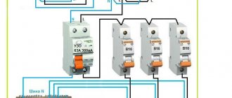
Electrical wiring in the house
Before connecting the generator to the house, I analyzed the state of the house network. After the meter I had two 25A machines. I decided to immediately change them, since the wiring in the house is old.
I have many articles on choosing a circuit breaker, here is the main one. Here, in relation to the apartment.
Counter and circuit breakers.
Third, IEK is not connected. The PVS cable that goes up goes to the summer kitchen. It was decided to install the generator near the summer kitchen, under a canopy, so power from the generator will come through this cable.
Possible mistakes
In addition to connecting a powerful power station to an outlet, the home owner is capable of making the following mistakes:
- Install the unit in a windproof basement, which can lead to overheating and concentration of toxic exhaust gases.
- Place the generator outdoors – the device can be damaged by snow or rain.
- Do not make grounding.
- Incorrect input cable cross-section.
- Perform switching of a switch or reversing device under load.
All these errors can cause a short circuit in the generator circuit with unpredictable consequences.
Generator autostart
Connecting the power plant to the home network through an autostart system - AVR - simplifies connecting the home to a backup power source. The system is equipped with an electric starter. The automatic start device controls the main network immediately after power is applied to it. The transfer to the backup power supply of the home network with automatic transfer switch occurs 10 seconds after the loss of voltage in the city main. Then the external network is turned off and the gas generator starts. After the engine warms up for 20 seconds, the installation is connected to the home network.
When voltage appears in the citywide main line, the source is switched off, and the home network begins to operate in standard mode.
Then the electric generator motor is turned off.
About contactors
Thus, the use of conventional relays is out of the question for us; only specialized contactors are suitable.
For higher powers there is also an option with motorized drives, but this is expensive and redundant for typical home use. To make a mechanical interlock, you need to select contactors that can work in pairs. Typically, mutual interlocking is achieved by installing identical contactors next to each other and installing an additional option - a mechanical interlock. It is sold separately from contactors and costs pennies.
Mutual electrical interlocking is possible if the contactor has additional signal contacts that operate to open. Sometimes they are immediately built into the contactor, sometimes they can be purchased and installed as an option.
Leading contactor manufacturers have such equipment in their lines. So finding and buying a kit is not difficult. True, prices for branded contactors are an order of magnitude higher than ours/Chinese ones. Since the number of switching cycles is not expected to be large, the choice of Chinese contactors is quite justified. The only disadvantage is that the contactor coils hum quite loudly during operation.
More about the switching power. The contactor contacts must be able to handle the maximum amount of power you are allowed to draw in your home. For me it is 10 kW, so I chose contactors for a permissible current through one contact of approximately 50 amperes. It is worth noting that for some reason the switched power for a typical three-phase contactor is indicated in the passport as the total for all three phases, so you need to carefully look at what the permissible current is through exactly one contact.
Using a changeover switch
When the input circuit breaker is turned off, the changeover switch connects power from the power plant . This happens in stages:
- Disabling circuit breakers.
- Connecting the switch wire to the generator.
- Starting and warming up the generator.
- Supplying power to the switch.
- Switching on automatic load switches.
When electricity appears in the main network, the generator is turned off, performing the above steps in reverse order.
Application of ABP
The autostart system is more expensive than the manual one , but it constantly monitors the network voltage. When the voltage disappears, the contactor interrupts the connection between the ATS and the central power grid. The starter turns on and the generator starts working. Most generator owners prefer using cheaper partial automation, which works as follows:
- The main power supply is connected through a contactor that opens when the input is disconnected.
- The gas generator is started manually. A time relay is installed in it to warm up the engine and automatically switch to connecting the reserve to the home network.
- When the power supply is restored, the contactor is switched off and the load is supplied again from the public network.
A fully automated power supply system regulates the operation of the gas generator using microprocessors. Video on this topic
Device and main parameters of generation
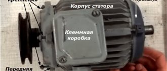
Three-phase generator design
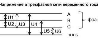
A three-phase generator is a device that operates on the principle of converting the mechanical energy of a rotating shaft into electricity. In addition to the moving part associated with the drive, it consists of three coils made up of many windings and placed on the stator core. In brushless generators, when the rotor rotates, an EMF is induced in the coils, whose parameters correspond to the standards of 3-phase mains power. This means the following:
- the resulting voltages have a sinusoidal shape;
- the amplitude of each of the 3 phases is 220 Volts;
- the voltage between them is 380 Volts;
- frequency of generated oscillations – 50 Hz.
A design feature of such units is a phase shift of 120 degrees.
An alternating voltage is supplied from the stator coils to the serviced line, providing it with the necessary power of 380 Volts.
Installation of the ground loop
To ground the electric generator yourself, you will need a copper wire , a metal rod 150 cm long and 1.5 cm in cross-section. The rod is driven almost its entire length into the soil. A special clamp or a regular bolt is welded to it for easier connection of the ground wire. The copper cable runs from the rod to the appropriate terminal on the backup source.
Or, an iron sheet measuring 0.5x1 m is used as a grounding conductor. The grounding conductor is buried in the ground and connected to the unit with a wire using clamps.
With a three-phase power supply in the house, experts advise making a backup of only one phase for connection to a gas generator. It will power the necessary equipment: refrigerator, lighting, computer.
Phase imbalance in a three-phase connection is a common occurrence, and it can damage the electrical wiring of the house.
If, even after reading the instruction manual, you do not know how to safely connect a gas generator to the network at home, you should seek help from specialists.
Difference between single and three phase connection
All connections, whether in a single-phase or a three-phase network, are made completely identical, with the exception of the number of power wires. The only important nuance concerns the so-called control phase - if you connect the starter to the network, then its main contacts connect and disconnect the power wires from the network, and the power for the electromagnetic coil must also be taken from somewhere.
In a single-phase network there are no problems - there is only one phase and such a question simply does not exist, but in a three-phase network everything is somewhat more complicated - there are L1, L2 and L3. Without going into technical details, there is only one answer - for control circuits you can use any of the phases, but only one. That is, if the KM1 coil is powered from phase L3, then the control of the remaining starters, the “Start” and “Stop” buttons must also be “hung” only on it.
This is not difficult to do - just note what color the wire is on the desired phase, and if the cable has single-color conductors, then stick or draw markers on them.