Purpose
The inductive sensor is designed to control the movement of the working element without direct contact with it. The main areas of application for it are machine tools, precision medical devices, process automation systems, measurement and control of product shape. In accordance with the provisions of clause 2.1.1.1 of GOST R 50030.5.2-99, this is a sensor that creates an electromagnetic field in the sensitivity area and has a semiconductor switch.
The scope of application of inductive sensors is largely determined by their high reliability and resistance to external factors. Their readings and operation are not affected by many environmental factors: moisture, condensation, accumulation of dust and dirt, ingress of solid particles. Such features are provided by their design and design data.
Capacitive proximity sensors
Capacitive proximity sensors can detect metallic and non-metallic objects, as well as amorphous products such as powders, granules and liquids. A good example of such a device is the CD50CNF06NO from Carlo Gavazzi. It operates similarly to inductive sensors, except that the inductive sensor coils have been replaced by a capacitive detector plate. Most often it is used to determine the level of liquid in tanks. The metal plate of the detector in this case forms a capacitor with the detected object, the capacitance of which changes with distance from the object. It defines the oscillator frequency, which is controlled to switch the output state whenever a threshold is exceeded.
The CD50CNF06NO sensor is designed to monitor liquid level. It is connected by three wires and has an open collector (NO) NPN transistor output. Requires a DC power supply of 10 to 30 V. It is available in a 50 x 30 x 7 mm housing and provides a detection range of up to 6 mm. Typically it is screwed or glued to the outside of a non-metallic tank.
Device
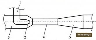
The development of the radio electronics segment has led not only to the improvement of the original mechanisms, but also to the emergence of fundamentally new inductive sensors. As an example, consider one of the simplest options (Figure 1):
Rice. 1. Inductive sensor device
As you can see in the figure, it includes:
- magnetic core or yoke (1) – designed to transmit the electromagnetic field from the generator to the sensitivity zone;
- inductor (2) – creates an alternating electromagnetic field when electric current flows through the turns;
- measurement object (3) – a metal armature inserted or moved into the sensitivity area; non-metallic objects are not capable of influencing the state of the electromagnetic field, therefore they are not used as a detector;
- the gap between the measurement object and the main magnetic circuit (4) – provides a measure of interaction as a magnetic dielectric; depending on the sensor model and the method of movement, it can remain unchanged or fluctuate within a given range;
- generator (5) - designed to generate an electrical voltage of a given frequency, which will create an alternating magnetic field in a given area.
Areas of use
The possible area of application of induction sensors is so wide that it allows them to be used not only in everyday life and the automotive industry, but also in industry with robotics, as well as medicine.
Medical devices
Inductive sensors are widely used in the production of medical equipment, since the magnetic properties of the device make it possible to record pulmonary ventilation, vibration parameters, and also take ballistocardiograms.
Appliances
In everyday life, sensors can act as a device for monitoring water supply, lighting level and door position (closed or open), therefore they are used in the production of, for example, washing machines and other household appliances. In addition, the devices are used in the process of creating smart home elements.
Automotive industry
An induction sensor is also used in the automotive industry, acting as a controller that determines the position of the crankshaft. When a metal object, in this case a gear tooth, approaches the device, the magnetic field generated by the built-in permanent magnet increases, which leads to the induction of an alternating voltage in the coil.
Attention! Some manufacturers are trying to change the design of the induction sensor to improve efficiency, for example, using external magnets to activate it.
Robotic equipment
In the case of robotics, inductive sensors have found application in the production of unmanned vehicles and industrial robots to increase their sensitivity to obstacles and the ability to recognize objects, as well as devices for which self-balancing is important.
Industrial control and measurement technology
They are widely used in the operation of conveyor systems, packaging machines and assembly lines, as well as as part of all types of machine tools and shut-off valves. Inductive sensors also help to monitor small and large elements of industrial equipment (gear teeth, steel flags, stamps), production objects (metal products, metal sheets, covers), etc. In addition, when connected to pulse counters, the result is a rudimentary but extremely effective reading device.
Principle of operation
The principle of operation of an inductive sensor is the ability of the electromagnetic field to change its parameters, depending on the value of magnetic conductivity along the flow path. Its operation is based on the classic version of a coil wound on a core.
Rice. 2. Magnetic field at rest
When electric current I flows through the turns of this coil, a magnetic field is generated (see Figure 2), the resulting magnetic induction vector B of which is determined by the Right Hand Rule. When the magnetic field moves along the core, the ferromagnetic material provides maximum throughput. But as soon as the magnetic induction lines enter the airspace, the magnetic conductivity deteriorates significantly and part of the field is dissipated.
Rice. 3. Magnetic field when introducing a trigger object
When a triggering object (Figure 3) made of metal is brought into the field of action of an inductive sensor, the intensity of the induction lines changes sharply. As a result, the flux increases and its value changes, and this, in turn, leads to a change in the electrical value in the coil circuit due to the phenomenon of mutual induction. In practice, this signal is too small, so to expand the measurement limit of the inductive sensor, an amplifier is included in their circuit.
Next generation induction sensors
Thanks to new developments in this area, improved models of next generation induction sensors have been created. The principle of operation remains the same, but the design of the device has been thoroughly redesigned. As a result, sensors are now equipped with thin 3D printed circuit boards and advanced digital electronics. In addition, they are produced on flexible substrates, eliminating the need for traditional cables and connectors. So you can use the devices even in difficult weather conditions.
The advantages of new developments include the following:
- reduced cost and weight, more compact dimensions;
- the ability to choose almost any form factor;
- increasing the accuracy of response to metal objects;
- the ability to take measurements involving complex geometries in two or three dimensions;
- simplification of design;
- the ability to install several induction sensors close to each other due to high electromagnetic compatibility.
Sensing distance and target
Depending on the design and operating principle of the inductive sensor, the object of influence may have vertical or horizontal movement relative to the meter itself. However, the sensor’s response to the start of movement of the controlled object may not begin immediately, which is determined by the nominal distance at which the sensor’s sensitivity zone is ensured and the technical parameters of the object.
Rice. 4. Trigger area and object
As you can see in Figure 4, in the first position the controlled object is located at a distance where the electromagnetic lines do not reach its surface. In this case, the signal will not be collected from the inductive sensor, since it does not detect movements in the sensitivity zone. In the second position, the controlled object has already crossed the sensing distance and entered the sensitive zone. As a result of interaction with the object, a corresponding signal will appear at the sensor output.
Also, the sensing distance will depend on the geometric dimensions, shape and material. It should be noted that only metal objects are used as an object for triggering an inductive sensor, but the moment the sensor transitions to the opposite state will also differ from the specific type, which is shown in the diagram:
Rice. 5. Dependence of the sensing distance on the material
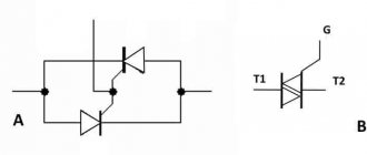
Transistor pairs in electric motor control circuits
They are also used in H-bridge control circuits for reversible DC motors, which make it possible to regulate the current through the motor evenly in both directions of its rotation.
The H-bridge circuit above is so called because the basic configuration of its four transistor switches resembles the letter "H" with the motor located on the cross line. The transistor H-bridge is probably one of the most commonly used types of reversible DC motor control circuit. It uses “complementary” pairs of NPN and PNP transistors in each branch to act as switches to control the motor.
Control input A allows the motor to run in one direction, while input B is used for reverse rotation.
For example, when transistor TR1 is on and TR2 is off, input A is connected to the supply voltage (+Vcc), and if transistor TR3 is off and TR4 is on, then input B is connected to 0 volts (GND). Therefore, the motor will rotate in one direction, corresponding to the positive potential of input A and the negative potential of input B.
If the switch states are changed so that TR1 is off, TR2 is on, TR3 is on, and TR4 is off, the motor current will flow in the opposite direction, causing it to reverse.
By using opposite logic levels "1" or "0" on inputs A and B, you can control the direction of rotation of the motor.
Kinds
In practice, there is a huge variety of inductive sensors, all of them can be divided into two large categories, depending on the type of supply current - alternating and direct. Depending on the state of the contacts in accordance with Table 1 p.3 of GOST R 50030.5.2-99, inductive sensors are:
- closing – when moving the controlled object, it is switched to the on position;
- opening – in case of impact, the inductive sensor moves the contacts to the off position;
- switching - simultaneously combines both previous options, in one switching it moves one output to the on position, the second to the off position.
Based on the number of measuring circuits, inductive sensors are divided into single and differential. The first of them has one coil and one measuring circuit. The second type involves the presence of two sensors, the measuring circuits of which are switched in antiphase to compare readings.
Rice. 6. Single and differential sensor
Based on the method of data transmission, inductive sensors are divided into analog, electronic and digital. In the first case, the same coils and ferromagnetic cores are used. Electronic ones use a Schmidt trigger instead of ferromagnets to produce a hysteresis component. Digital ones are made in the format of printed circuit boards on microcircuits. In addition, the types are divided by the number of sensor pins: two, three, four or five.
Ultrasonic proximity sensors
When long distances are required, such as detecting a car in front of a garage door, ultrasonic sensors are suitable. They detect all kinds of objects at a distance of up to several meters. The basis of the measurement is the time of flight of an ultrasonic pulse emitted by the transmitter, which is reflected from the target object and received by the receiver.
Knowing the speed of propagation of ultrasound, the distance can be calculated. In the example presented, the signal transit time is 3 ms. For air at 21 C, the speed of sound is 343 m/s, so the total distance to the object is 60 cm.
The MatBotix MB1634-000 is an ultrasonic proximity sensor with a range of up to 5 m, powered from 2.5 to 5.5 V. It provides an output of an analog signal, a PWM signal, or can transmit digital data serially with TTL voltage levels. It has automatic compensation for changes in object size and a built-in stabilizer. Optional external temperature compensation is available.
Characteristics (parameters)
When choosing an inductive sensor to solve a specific problem, they are guided by the parameters of the circuit in which it will operate and the basic logic of the circuit. Therefore, the compliance of their parameters must be checked:
- supply voltage - determines the permissible minimum and maximum potential difference at which the inductive sensor operates normally;
- minimum operating current – the lowest load value at which switching will occur;
- actuation distance - the permissible distance distance at which switching will occur;
- inductive and magnetic resistance - determines the conductivity of electric current and magnetic induction lines for a specific model;
- correction factor - used to make corrections, depending on additional factors;
- switching frequency – the maximum possible number of switching times per second;
- overall dimensions and installation method.
Steam pipeline monitoring
LOCA (Leak Coolant) describes a reactor coolant leak accident that may be caused by a piping system failure. In the worst case, it can be assumed that both ends of the pipe are cut off and the leak occurs through a double section of the pipeline. The emergency cooling system and the size of the reactor reserve capacity are calculated accordingly. Backup systems must be accessible, damaged pipelines must be closed with emergency valves in a short period of time. The causes of an accident can be different, such as an earthquake, plane crash or tsunami.
Another possible phenomenon is water hammer, which can occur in hot steam lines when some of the saturated steam condenses and accumulates in the pipe due to insufficient drainage, so that suddenly in certain sections of the pipe the entire cross-section is filled with water. The water column is accelerated by steam pressure, and an impact occurs, similar to the action of a cylinder piston. Subsequent bends in the pipeline present an obstacle to the water column and its mass inertia. The pressure in the pipeline network increases rapidly and is several times higher than the maximum steam pressure and can exhaust the design safety margin of the pipeline, leading to deformation or rupture of the pipe.
Monitoring of power plant pipelines
In both LOCA and water hammer accidents, it is important to continuously monitor elements critical to plant safety, such as cooling lines and superheated steam lines, and, if necessary, shut them off immediately using emergency valves. Duplicate systems take over the functions. An effective safety device consists of installed pipeline displacement sensors based on the full inductive bridge (LVDT) principle. An inductive displacement sensor transmits data about the position of the pipeline in the form of a signal to the control panel. In addition, low-frequency vibrations of pipelines can serve as a signal of a possible accident. The position of the pipelines at several different points is displayed on the station control panel. If the measurement result falls outside the preset threshold values, taking into account possible calculated movements and vibration amplitudes, an alarm is generated and the established emergency procedure is carried out.
Installation of an inductive linear displacement sensor for monitoring steam pipelines (pipe position measurement)
The measurement ranges of inductive linear displacement sensors are used from 100 to 300 mm. The sensors themselves must withstand extreme operating conditions without damage, such as a maximum temperature of 180°C, a steam-air mixture of 100% (relative humidity) and condensation of 0.5 kg/m³ at a temperature of 125°C. Eddylab sensors designed for this task consist of a cylindrical body and a movable rod. The body is attached to a fixed structure using clamps, the rod is connected to the pipeline. If the steam line moves with the rod relative to the sensor body, the output signal changes. The monitoring results are transmitted in the form of a continuous position signal to the station control system.
Internally, the sensor consists of a coil system (primary and secondary) in a sealed housing with Viton O-rings. The IMCA electronics feed the primary LVDT coil with a 3 kHz carrier signal and analyze the differential voltage across the secondary coil for amplitude and phase. The advantage of this system is that a long cable can be used between the sensor and the electronics, so that the electronics can be kept in a safe location 100 m or more away, while the sensor can be exposed to extreme conditions at the installation site without problems.
Two-wire inductance sensors
Rice.
7. Connection diagram for a two-wire sensor As you can see in the diagram above, two-wire inductive sensors are used exclusively for direct load switching: contactors, starters, relay coils as an electronic switch. This is the simplest circuit and model, but the operation of a particular model greatly depends on the parameters of the connected load.
Field of application of inductive sensors
Inductive proximity sensors are often used as limit switches. Such devices have become widespread:
- in security systems, such as sensors for unauthorized opening of windows and doors;
- in telemechanics systems, as sensors for the final position of components and mechanisms;
- in everyday life in circuits indicating the closed position of doors and sashes;
- for counting objects (for example, moving along a conveyor belt);
- to determine the rotation speed of gear wheels (each tooth, passing by the sensor, creates an impulse);
- in other situations.
Angle position sensors can be used to determine the rotation angles of shafts, gears and other rotating components, and also as absolute encoders. Also, such devices can be used in machine tools and robotic devices along with linear position sensors. Where it is necessary to know exactly the position of mechanism components.
Three-wire inductance sensors
Rice.
8. Connection diagram for a three-wire inductance sensor In a three-wire circuit, there are two outputs for powering the inductive sensor itself, and the third is intended for connecting a load to it. According to the switching method, they are divided into PNP and NPN, the first type switches the positive terminal, hence the name, the second type switches the negative terminal.
Marking upon connection
On circuit diagrams, inductive sensors are usually designated as a diamond or square with two vertical lines inside. Often they also indicate the type of output (normally open or closed), corresponding to one of the types of semiconductor transistors. Most circuit options specify a normally closed group or both types in one package.
Color coding of terminals
Before installing the sensor, it is necessary to check the data with the instructions.
In practice, a standard system for marking the terminals of inductance sensors is used, which is followed by all manufacturers of sensitive devices without exception. However, before installing them, it is recommended to carefully monitor the polarity of the connection and be sure to check the instructions supplied with the products.
On the housings of all sensors there is a drawing with color markings of wires, if its dimensions allow it.
Standard notation:
- Blue always means negative power bus;
- brown color indicates the positive conductor;
- black corresponds to the sensor output;
- White is an additional output or input.
To clarify the last marking, it should be checked against the instructions supplied with the specific device.
Four-wire inductance sensors
Rice.
9. Connection diagram for a four-wire inductance sensor By analogy with the previous sensor, the four-wire also uses two pins 1 and 3 to receive power. But pins 2 and 4 are used to connect the load with the difference that the switching for both loads will be opposite.
Optical proximity sensors
Optical proximity sensors (see review and testing link) use infrared or visible light for detection. They have the advantage that the object being observed does not have to be magnetic or metallic - it just needs to hide or reflect light. Most optical sensors emit a beam in the direction of the object and monitor the reflected light.
The EE-SY1200 sensor from Omron Electronics is a good example of an optical proximity sensor. It is an ultra-compact PCB mounting solution that uses infrared (850 nm) radiation. The detector consists of an LED emitter and a pair of phototransistors in an SMD package measuring only 1.9 x 3.2 x 1.1 mm. The recommended detection range is 1-4mm. Thanks to its small size, it can be integrated directly into devices without the need for wiring harnesses and connectors, for example using flexible substrates.
Five-wire inductance sensors
Rice.
10. Connection diagram for a five-wire inductive sensor In a five-wire inductive sensor, two pins are used to supply voltage to the sensitive element of the sensor, in the example under consideration these are 1 and 3. Two pins 2 and 4 supply power to different loads, and control pin 5 allows you to select different operating modes and change the switching logic.
What's new in the VK SamElectric.ru group?
Subscribe and read the article further:
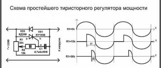
So, the diagram is on the left. Let's assume that the sensor type is NO. Then (regardless of the type of transistor at the output), when the sensor is not active, its output “contacts” are open and no current flows through them. When the sensor is active, the contacts are closed, with all the ensuing consequences. More precisely, with current flowing through these contacts)). The current flowing creates a voltage drop across the load.
The internal load is shown with a dotted line for a reason. This resistor exists, but its presence does not guarantee stable operation of the sensor; the sensor must be connected to the controller input or other load. The resistance of this input is the main load.
So, in a circuit with a PNP output, when activated, voltage (+V) is supplied to the controller input through an open transistor, and it is activated. How can we achieve the same with NPN output?
We look at the changes in the diagram on the right. First of all, the operating mode of the sensor output transistor is ensured. To do this, an additional resistor is added to the circuit; its resistance is usually about 5.1 - 10 kOhm. Now, when the sensor is not active, voltage (+V) is supplied to the controller input through an additional resistor, and the controller input is activated. When the sensor is active, there is a discrete “0” at the controller input, since the controller input is shunted by an open NPN transistor, and almost all of the additional resistor current passes through this transistor.
In this case, a rephasing of the sensor operation occurs. But the sensor works in mode, and the controller receives information. In most cases this is enough. For example, in the pulse counting mode - a tachometer, or the number of workpieces.
Yes, not exactly what we wanted, and interchangeability schemes for npn and pnp sensors are not always acceptable.
How to achieve full functionality? Method 1 – mechanically move or remake the metal plate (activator). Or the light gap, if we are talking about an optical sensor. Method 2 – reprogram the controller input so that discrete “0” is the active state of the controller, and “1” is the passive state. If you have a laptop at hand, then the second method is both faster and easier.
Advantages and disadvantages
Compared to other types of sensor devices, inductive sensors continue to occupy a significant niche, increasing the pace of implementation in various fields of industry and sectors of the national economy. This frequent use is explained by a number of significant advantages:
- high reliability due to simple design and absence of moving contacts;
- can operate both from a household network and from special generators, converters and other power sources;
- capable of providing significant output power - on the order of several tens of watts;
- characterized by high sensitivity in the measurement zone.
But, at the same time, there are also disadvantages of inductive sensors that do not allow their use everywhere. Among the most significant disadvantages are their bulky dimensions, which do not allow them to be mounted in any devices. Disadvantages also include the dependence of operating parameters on temperature and other factors that correct for accuracy.
Errors
Errors in the process of converting diagnostic values affect the ability of induction sensors to provide reliable information. The main ones include the following.
Electromagnetic
This error is usually taken into account only as a random variable. As a rule, it occurs during the induction of EMF in the induction coil as a result of external influence by external magnetic fields. This occurs during the manufacturing process due to power electrical devices. They form magnetic fields, which subsequently forms an electromagnetic error.
From temperature
This error also acts as a random value, since the operation of a large number of elements of the induction sensor directly depends on temperature indicators, so this is a key quantity that is even taken into account in the design process of such equipment.
Magnetic elasticity
Typically, such an error can manifest itself as a consequence of instability in the deformation of the magnetic circuit of the device during the assembly of the sensor itself, as well as during deformation changes during operation. In addition, the effect of unstable electrical voltage on the magnetic circuit of the equipment causes a decrease in the quality of the transmitted signal at the output.
Deformation of elements
This error, as a rule, manifests itself as a result of the influence of the measuring force on the deformation value of the parts of the induction sensor, as well as under the influence of forces exerted on unstable deforming processes. In addition, it can be equally influenced by backlashes and gaps formed in the moving elements of the device’s structure.
Cables
Such an error usually manifests itself from an unstable resistance value, in the case of deformation of the wire itself and under the influence of temperature. Also, interference from external EMF fields in the cable can have a similar effect.
Aging
This error can manifest itself when the moving elements of the device itself wear out, as well as in the case of constantly changing magnetic properties of the magnetic circuit used. It is generally considered to be, strictly speaking, a random value. In the process of determining this error, the kinematics of the induction sensor design are taken into account, and during the design of such equipment, it is recommended to determine the maximum operating life only when operating in normal mode, so that wear does not have time to exceed the set value.
Potentiometer
Potentiometer is a variable resistor. The potentiometer has a durable metal or plastic knob connected to a slider that allows you to adjust the resistance, after which the alternating voltage is divided. In symbols and notations, the symbol of a potentiometer is a resistor with an arrow passing through it.
The arrow is the third connection and shows that the potentiometer is a variable resistor.
Potentiometers are widely used in modern electronic devices. When it comes to cars, variable resistors can be found in the throttle position sensor and in the accelerator pedal position sensor.
The potentiometer includes electrical connections, an adjustment axis, a variable resistance track, a resistive track for variable resistance, a moving contact (sliding element), a slider, a body, and the potentiometer has two circular tracks: an outer one and an inner one.
The outer track is made of hydrocarbon, so it creates resistance. The inner track is made of highly conductive material.
Depending on the nature of resistance measurement, linear and logarithmic potentiometers are distinguished. In logarithmic potentiometers, the resistance value is increased using a logarithmic function. When the slider starts moving, the resistance changes quickly and then slows down.
Are you already using ELECTUDE modules for training and advanced training of automotive electricians and diagnosticians?
Non-contact sensors with NAMUR output
The voltage and current ratings of switches with NAMUR are so low that they can be used safely in explosive environments. The model number of devices in this line contains the letter "N" after the identification number, sometimes in combination with a number.
Power limitation is implemented in appropriate equipment. This means that a NAMUR proximity sensor will only be intrinsically safe if it is powered through a suitable isolated amplifier.