To be able to switch electricity to the necessary devices, special devices are installed - changeover switches. An important part of their design are blockers. There are different versions of such devices on the market; they are distinguished primarily by their performance characteristics.
It must be taken into account that devices are connected using different circuits depending on the types of electrical networks. Their operating parameters can be adjusted using control units. Also, similar switches are used in industrial production, where they serve backup generators.
To understand especially the connection diagrams, you need to familiarize yourself with the types of devices that are presented in our country.
Scope of application of circuit breakers and switches
From all of the above, it is clear that such devices are designed to switch circuits that under no circumstances should be connected to each other.
One striking example is switching an object to a backup source. Suppose you are tired of constant power outages in your country house and have acquired a gas generator. The electricians turned off the power, you switched to the generator. Turned it on - you are powering your house again from the standard network. Everything is simple in words, but how to do it practically? This is where a changeover switch will help you out. Take a look at the diagram below: In one switch position the house is connected to the mains, in the other it is connected to the generator. Moreover, even if there is voltage in both the network and the generator, switching does not threaten anything - it is impossible to connect the network to the generator. Unfortunately, although this scheme is simple, it is not entirely correct. Let's look at the actions you must take when connecting the generator:
- Disconnect the house from the standard electrical network.
- Start the generator and bring it into operating mode.
- Connect the house to the generator.
You don’t need to be a rocket scientist to understand that it is impossible to perform such a sequence of operations with a conventional changeover device. You will either have to start the generator first and then switch, or switch sources and then start the generator.
If the first option is still suitable, then the second is absolutely unacceptable for most household appliances. How will a refrigerator feel, for example, if during the startup of a gas generator the supply voltage begins to rise from 0 to 220 V, and the frequency from 0 to 50 Hz? If you don't know, it will burn.
Full automatic transfer switch
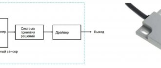
In order to fully automate the process, you need more than 2 relays - a full-fledged control system. Such a system exists and is called AVR - Automatic Reserve Entry. Such devices are created on the basis of programmable AVR controllers and contain many feedback sensors and regulators. Only a qualified specialist can make such equipment independently.
But you can equip your home or any other object with such a machine - they are on sale, although they are not cheap. But the list of functions performed by a standard ATS is quite large:
- Disconnection of consumers from the main source when the supply voltage is lost.
- “Smart” generator start with control of unsuccessful start.
- Bringing the gas generator to operating mode.
- Connecting consumers to the generator line.
- Counting engine hours, monitoring engine temperature, fuel consumption, etc.
- Monitoring voltage, frequency and current with automatic adjustment of the generator operating mode.
- Automatic switching to the main source when normal power supply is restored.
- Stopping the gas generator.
- Charging the starter battery.
Today you can buy an AVR unit either complete with a gas generator or separately. The first option, of course, is simpler (the nodes are adapted and connected to each other by the manufacturer), but it is not financially justified if a generator is already available. In this case, it is enough to purchase an ATS, but before purchasing, be sure to consult with a specialist about whether a specific machine model can work with your generator. The block diagram of connecting a generator with an ATS to a home network will look something like this:
Distribution board diagram with a “network-generator” switch
Details Published: 04 June 2015
In dacha areas, garden plots, the private sector and similar places, frequent power outages are common. Here they can turn off the lights for an hour, for the whole day or for a longer time. This creates quite a few problems, since people can no longer imagine life without electricity. He has things working at home: a refrigerator, a TV, room lighting, a pump for watering the garden, and the like.
Gasoline power plants are very popular in such places. Turn off the lights, start the gas generator and continue to enjoy life. The power plant must be connected to the distribution board through a special outlet. Below I look at the diagram of a distribution board with a “mains-generator” switch, which allows you to switch to power supply from a gas generator when the external network is lost and back.
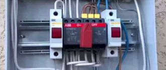
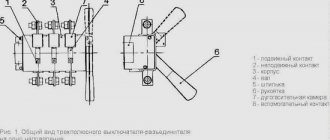
Here I am considering manual switching, which is carried out using a reversing switch. All diagrams show an ABB OT40F3C switch. This is a high-quality and reliable reversible switch. It has three positions:
- the handle is turned to the left - the contacts on its left side are closed, and on the right side they are open;
- the handle is in a vertical position - all contacts are open (both right and left);
- the handle is turned to the right - the contacts on its right side are closed, and on the left side they are open.
If what is written is not entirely clear, then look at the latest diagram and you will immediately understand how it works.
It is worth noting that if you take such a reversing switch for a higher current, then the switch handle is not included in the kit. It must be purchased separately.
Below is a simple single-phase switchboard diagram with a mains-generator switch. This is plenty for a small dacha or garden house. If you have a large house, then you need to revise the ratings of the input machine and increase the number of group lines. Everything is individual here.
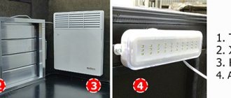
It is very convenient to use a network indicator in such panels. For example, the signal lamp LS-47. Why is she needed here? Let's say the lights are turned off and you start the power plant. Everything is working.
Next, how to determine whether there is voltage in the network or not? You won’t run to the switchboard every half hour and use an indicator to check whether the light is on or not. This is not convenient and is forgotten over time. So you can miss this moment and “sit” on the gas generator until the evening. And gasoline is expensive these days.
In such a situation, the mains voltage indicator will immediately show you when the light comes on
It will just light up and you will immediately notice it. It is clearly visible from afar even through the transparent cover of the shield
As soon as the warning light came on, they immediately turned off the power plant and switched the switch to mains mode.
Below is the same diagram of the distribution board, but with an LS-47 signal lamp.
If you want to protect yourself and your dacha from current leaks, then you need to install an RCD. Below is a diagram with one common protective device. If you want more, then go ahead and fight. Here you can fantasize endlessly.
For a better understanding of the operation of such a circuit, I schematically showed the state of the contacts of the reversing switch with red lines and the direction of the current with red arrows.
Below is the work from an external network.
And here the work from a gas generator is already presented.
And these are already two diagrams of the operation of this switchboard in one. It looks like a cartoon. Like?
At the request of site visitors, I am posting below a 3-phase electrical panel diagram with a “network-generator” switch
Also don't forget to smile:
A drunk man goes home and hits his head on every lamppost. Then an acquaintance meets him and asks: “Why are you hitting the pillars like that, why are they bothering you?” Can't get around? “That’s not the point at all, it’s just how I determine the way home.” - Didn't understand. - What’s incomprehensible here? Here are 3 more pillars along this street, then 7 more along another - and I’m home.
Connection features
The choice of connection diagram for a changeover switch is influenced by the type of electrical network.
Single-phase network
You can connect such a device to this network only if it has two poles. In addition, you need to take into account that the operation of the switch is only possible if there is a power supply with suitable technical characteristics. As for jumpers that provide contact between two-pole devices, it is advisable to give preference to copper ones.
Two-phase network
How to connect a switch with your own hands if the network is two-phase? The circuit involves the use of a 200V power supply. Also, for these devices you need to use only expansion switches. Only then can the devices be used in a three-phase power supply network, regardless of the number of modules used.
The maximum voltage for such devices will be 300V, and the maximum negative resistance will be 40 Ohms. The contacts in such devices are applicable exclusively to closed models, and fluctuations in electrical energy are controlled using pass-type capacitors.
Three-phase network
For this type of electrical network, reversible switches are used. They provide a complete uninterrupted supply of electric current, distributing the load over several lines and completely preserving the power supply. Here you need to use 400 V power supplies. It would also be appropriate to use pulse transformers.
Designs of chippers
Changeover switches are available in two main versions.
- Single pole switch. It has a single module and is connected using copper conductors. This option is considered the most optimal for generators with an operating frequency range of no more than 20 Hz. These devices have certain limitations, for example, the maximum load is only 200 amperes. Therefore, installing single-pole switches in residential buildings with high electricity consumption is impractical. Another disadvantage is the low output voltage, averaging 200 volts.
- Double pole switch. The most common type of alternator circuit breaker with two poles is used in modern electrical circuits. These devices are most suitable for residential buildings. They can be used together with devices connected to single-phase and two-phase networks. The average negative resistance for such switches is 60 Ohms. The output voltage may differ depending on the modification of the device. Currently, PP20 series switches with open-type capacitors are widely popular. Along with them, the circuit contains power supplies with an operating voltage of 300 volts.
Tags: machine, ampere, sconce, type, choice, switch, generator, house, , sign, cable, like, capacitor, design, , magnet, installation, power, load, voltage, nominal, changeover switch, connection, principle , wire, start, , work, size, repair, switch, row, light, network, system, connection, resistance, stabilizer, circuit, ten, type, current, transformer, three-phase, , installation, photo, shield, electricity, power supply , electrical panel, effect
How to connect a generator
I didn’t want to connect the generator through the ATS circuit, because I don’t have the knowledge or funds for this, but I decided to do everything myself and connect it without automation.
The store advised me to connect the generator directly through the outlet, but I did not do so for safety reasons. And they offered and sold me this adapter:
Cable with plugs for connecting the generator to an outlet
To make using the generator safer, I made the following socket for it on the wall of the summer kitchen:
Generator socket
The SSI-114 type socket has a cover that protects live parts. But there will always be voltage on it - both when the generator is running and from the street! I secured it higher so that the children couldn’t reach it.
I made another adapter for connection so as not to confuse it with anything else, and signed the danger warnings.
Connection cable
The fork looks like this:
Generator output plug
This is the most dangerous place in the structure. But how to avoid trouble is the secret in the connection sequence, more on that later.
Connection diagrams
Please note that the procedure for connecting the device may differ depending on the type of electrical network.
Connecting devices to a single-phase network
Connecting such a switch to a single-phase circuit is possible only if the selected device is made in a two-pole version. It is also necessary to keep in mind that this device can only function with a power supply whose operating voltage is 300 V.
- For such a modification, the negative resistance indicator will reach 50 Ohms. An important point is that sometimes these switches are supplemented with counters. But such a device as switches can rarely be found when using changeover switches.
- When choosing jumpers to ensure contact between two-pole modifications, only those made of copper should be used.
- To install such devices in residential buildings, you should make sure that there are electrical panels of the KK202 series and other modifications. Due to the discrepancy in performance characteristics, reversing units are not recommended for single-phase circuits.
Connecting the device to a two-phase network
If we talk about the voltage limit with which they are able to cope, then this is the level of 300 V. In such a combination, these switches will be subject to a load that will be about 20 A. Most often, the choice is made on such models of switches, which represent the PP30 series.
According to their design, they are equipped with only two modules. With this design, they will be able to provide an output voltage corresponding to a value of 350 V. The blockers used in them can have different designs
For servicing residential buildings, it is important to ensure that there is an electrical panel. This is a requirement
But the design of control units usually contains thyristors. For the network, the limit of negative resistance is 40 ohms. The contact systems that are implemented in such switches are applicable only to closed-type models. In this case, control of electricity fluctuations is ensured by feed-through capacitors. A device such as a reversing unit performs the task of maintaining the required current frequency. If the choice was made on two different models, then they must be used in combination with the controller. This, in turn, makes it possible to minimize the negative effect of nonlinear distortions that appear in the circuit.
Connection diagram to a three-phase network
In the case of installing a switch in a three-phase circuit, it is necessary to use power supplies with an operating voltage of 400 V. It is worth noting that for such purposes it is allowed to use transformers made exclusively in the pulse version.
- The procedure for connecting the device itself is performed using an inverting input. The output current is supplied through a special device, the role of which is performed by pass-through capacitors. For such cases, it is advisable to use switches of a two-module design.
- At the same time, single-module modifications can also be found on sale. Their feature is the minimum threshold voltage limit, corresponding to a level of 350 V. As for the negative resistance indicator, its value in the circuit can correspond to a value of 55 Ohms. To solve this problem, care should be taken to ensure that the design of the switch contains a device such as a blocker.
- Residential buildings must be equipped with special electrical panels, representing the KK22 series. Control units used for such situations can include in their design not only thyristors, but also dinistors.
Choice
The buyer must determine from the very beginning which technical parameters are the most important for him. It is worth taking a closer look at these indicators:
- Weight.
- Dimensions.
- Power.
- Fuel consumption.
- Noise level.
- Duration of work.
Automation and price are parameters that are also being looked at
This is important for those who are interested in how to connect a generator to the home network, the diagram of which is posted on specialized websites
Generator operation
By parameters
Many people first look for an answer to the question of how many phases a generator should have for maximum convenient operation. To do this, you need to understand what electrical appliances will be connected. Three-phase options allow connection to both single- and three-phase devices. Single-phase ones are combined with only one type of consumer. But this does not mean that models with more phases will be better under all circumstances.
At each phase, the maximum load should be no more than 30%. This means that in reality the owners will not be able to use more than a third of the rated power that the outlet initially has. For example, the rated power of a three-phase generator is 6 kW. This means that no more than 2 kW can be removed from a regular 220 V outlet. The load still needs to be distributed over several phases when connecting a single-phase generator to a three-phase network at home.
You might be interested in Autonomous solar power plants for the home
Note! For power, they also check the parameters of the devices that are planned to be connected
It is important to have a reserve of at least 20-30%. Otherwise, you may encounter problems such as overload and work stoppage.
Too much fuel will also be consumed
Otherwise, you may encounter problems such as overload and work stoppage. Too much fuel will also be consumed.
Connection work
Type
Synchronous and asynchronous types of devices are available. The choice involves a careful study of the characteristics of each of the existing models.
Network device
Asynchronous
Their main problem is their inability to handle so-called peak loads. Although these devices can also be used to maintain normal voltage readings. They are suitable for joint use with equipment sensitive to voltage surges:
- Electronic devices.
- Computer Engineering.
- Medical devices supporting gasoline generators.
Residual magnetization of the rotor is the main source of energy for such devices. Therefore, the service life of asynchronous generators is longer than that of their closest analogues. They do not require the use of cooling systems; the unit housing is completely closed. Thanks to this, protection from dust and moisture is fully guaranteed.
Interesting! The asynchronous generator is immune to short circuits. Therefore, this energy source is the optimal solution for welding machines. But such devices can be very sensitive to overloads. Therefore, it is prohibited to connect them to devices with initially high inrush currents.
Devices with autostart
Synchronous
The quality of the current in this case is lower when compared with the previous option. Suitable for providing emergency power in various circumstances:
- Offices.
- Refrigeration units.
- Electrical equipment in dachas and country houses.
- Construction projects.
Such devices also have some positive qualities:
- Resistance to short-term overloads.
- Ability to normally withstand peak loads, including mechanical loads.
But protection from moisture, dust and dirt is worse than that of asynchronous structures. After all, in order to cool, such generators need to pass a certain amount of air through themselves. A synchronous generator will be needed if devices operating with reactive loads are used. Then the power will be less.
Changeover switches
Phasing
It has already been mentioned above. It is worth buying three-phase generators only if there is a consumer with the appropriate characteristics in the house. If all the devices are single-phase, then the generator is selected of this type. This even applies to situations where there is a three-phase network connected to the house.
Network connection
How to connect a generator to the network at home: diagram
The circuit is made for an electrical network and a generator. Switching can occur in manual or automatic mode
It is especially important where the insertion point of the switch is located. It must be located after the electric meter, but before the protective device
Let's first study the manual switching circuit. If the voltage disappears, use a switch or circuit breaker to break the connection to the central network and activate the generator. The switch must not implement these two actions at the same time. Be sure to provide a neutral position in the installation for subsequent connection.
It turns out that changeover or reversing switches can serve as a manual switch. When making a choice, you need to take into account the rated currents so that they are not lower than what is consumed. The process of how to connect a generator to the network at home varies. The layout and even the design of the devices may also differ. Look at the image below. It shows the connection of a three-phase generator.
In addition to the manual method, sometimes an indicator is installed that determines the presence or absence of voltage in the centralized network. An example of devices would be 220 V modular indicators or 220 V light indicators (twenty times cheaper), which have a closed housing and ready-made wiring. Their disadvantage is that they are connected to the fuse.
When automatically switching an electric generator, as the name implies, the process occurs without human intervention, automatically. The function falls on the ABP block. It consists of various devices: switches, indication parts, voltage control relays, contactors.
Such a generator must be equipped with an electric starter. To enable the reserve, the centralized network is turned off, the generator starts, warms up, and the wiring is connected to the consumer network. If voltage is supplied to the network again, the process is turned off in the reverse order.
Backup automatic entry can be carried out by different systems. You can look at the process by taking the GG700E gasoline generator model as an example. The connection starts after the voltage from the centralized network disappears. In just twelve seconds, all consumers at home will be provided with electrical energy.
The system is also capable of monitoring the stability of the energy supply. If operation occurs smoothly and continuously for more than ten seconds, then power begins to be supplied again through the common network. The device continues to operate for a few more seconds to check, and then turns off.
How to make a pass-through switch with your own hands - labor lesson
You've probably already looked at electronic catalogs and noticed that a triple pass-through switch can cost a lot of money. What to do? – The eternal Russian question, reinterpreted by Shakespeare as to be or not to be. We would choose the first: definitely not everyone is able to pay that kind of money for pass-through switches. We present to the attention of our readers the first handmade product in RuNet, where it will actually be shown in pictures how to convert an ordinary switch costing around a hundred (this is a really cheap model) into an expensive thing - a pass-through switch. And without any special skills or special techniques.
We look at the first picture and see the switch from which the buttons have been removed
More precisely, it was also taken out of the socket (so to speak), but this is not important now. As you can see from the picture, we have a typical connection diagram for 2 keys
Just in case, the screws of the spacers of the socket box and the clamping contacts of suitable wires are shown and labeled with colored lines. Each and every one of them must be significantly loosened to remove the switch from the wall socket. Do not forget to turn off the power before this, and we also strongly recommend checking with a probe where the phase is located, and somehow draw these places directly along the cambric (plastic insulation of the core). In the future, all this will greatly simplify the process of reinstalling the switch.
Socket spacer screws
Now look at the next picture, which shows the other side of our future victim. In the good sense of the word, of course. Here we see the switch housing clamps that need to be unbent to remove the electrical part. All this is done with a regular screwdriver within a few minutes. Then you need to remove the spring pushers from the plastic frame. The easiest way to do this is with a thick slotted screwdriver. Thin just won't do. You will quickly understand this. There is no need to rush, because this place is the most difficult in the entire process of converting a conventional switch into a walk-through one. In the picture, the spring pushers have already been removed, and moving contacts are visible in the place where they were.
Movable contacts under spring pushers
We skipped the moment of removing the plastic part from the ceramic one (in the pictures), because in our opinion this does not require explanation. At the ends of the entire removed part of the switch there are two weak teeth. Just pry them off with a slotted screwdriver, and let's start converting a regular switch into a walk-through one. Now on the ceramic base of the switch we see groups of contacts:
Three groups of contacts
- General group contact pads.
- Individual contacts for each light bulb.
- Movable rocker contacts.
Now all we have to do is rotate one rocker arm 180 degrees, and cut off one of the contact pads of the general group (it’s better not to isolate it). The resulting position is shown in the last picture. Now the final stage is how it all works. We take and glue both buttons with a Chinese gun so that they become one. Now that one of our contacts is closed, the second one will hang in the air.
Everything ingenious is simple. Therefore, in addition to the fact that we showed how to make a pass-through switch from a regular one, we will add that, in principle, it is not necessary to remove the spring pushers. You can do without this. And you don’t have to glue the two buttons together if you remove the key from a regular switch of the same width and the same manufacturer. Usually the pinout of the legs is exactly the same. All this will allow you not only to make a pass-through switch with your own hands, but also to produce a truly functional and beautiful product.
So, we believe that we have adequately covered the questions asked. They showed how to properly connect a pass-through switch, how not to do this and - most importantly - told how you can save a lot of money in the whole process. We hope that you will like the recommendations, and now every handy owner will be able to boast of having such an original design in his home. Well, what else would you call a pass-through switch?
Advantages and disadvantages of switches
It remains to consider the advantages and disadvantages of these devices. The advantages include:
- Visibility. The device usually has an open or semi-closed design, which means that its serviceability can be verified visually. Well, since you can clearly see the conductive knives and tires, it will not be difficult to determine in what position the breaker is located.
- Simple design. Almost all such switches, including changeover switches, have an extremely simple design. They are very durable, easy to maintain, and their repair usually does not require high qualifications and is inexpensive.
- High switching power/cost ratio. This is perhaps one of the main advantages of the devices. Some of these devices can switch currents of hundreds of amperes, and are relatively inexpensive.
But switch-type switches also have disadvantages. Here they are:
- Increased danger for the operator. Since most devices have an open design, it is very easy to get energized if handled carelessly. Therefore, only qualified personnel are usually allowed to work with such switches, and the switch itself is often placed in a closed cabinet or housing.
- Irregular switching time. The switching speed of almost any switch depends only on the operator’s reaction. When the knives are slowly moved under load, a high-temperature arc can “stretch” between the opening contacts, which is equally dangerous for both the equipment and the operator himself*.
Arc suppression inserts, which are equipped with some types of switches, help fight the arc only partially. That is why the vast majority of electrical equipment manufacturers recommend switching using switch devices only after removing the load using intermediate circuit breakers.
Requirements for backup power equipment
The need to switch to a backup source is usually caused by either an emergency or an abnormal situation. In this regard, all switching is often carried out by unqualified personnel and often in difficult conditions - in the dark, in cramped conditions, in the open air. That is why the requirements for redundant equipment are quite stringent:
- Safety for the operator. All backup electrical equipment must not have exposed live or moving parts (except for drive handles), and its metal chassis and casings must be grounded. When sending even an untrained person to switch, you must be sure that he will not come under voltage or injure his hands with any clamps or rods, even when working in poor lighting.
- Safety for electrical equipment. The switching circuit must be such that even if the switching is not completed completely or in the wrong sequence, the operator cannot create an emergency situation - apply counter voltage, switch not all phases, cause a short circuit, etc. All this will ensure the safety of the main and backup circuits even when inept or erroneous human actions.
- Efficiency. The transition to a backup generator should require minimal manipulation and be done as quickly as possible. The switching devices themselves should be as accessible as possible so that there is no need to climb ladders or climb hatches to get to them. This is especially important for critical facilities and special electrical equipment (refrigeration units, microclimate systems, boilers, furnaces, etc.).
- Clarity and simplicity. The design of switches and circuit breakers should be as simple as possible, and the switching diagram should be clear and intuitive. This significantly reduces the likelihood of human error and equipment failure. Such circuits are easier to maintain, and repairs if they break will cost less.
It is worth noting that no matter what method of switching to backup power you use, manual or automatic, all conditions should be met as much as possible. After all, not only ensuring uninterrupted power supply to the facility, but also the safety of people will depend on this.
How to connect a power plant to a house via a changeover switch
Remember that the generator must be completely disconnected from the existing electrical network, i.e. It is necessary to disconnect not only the phase, but also the zero.
The simplest and most inexpensive ways to connect a generator to your home with your own hands:
- Through a changeover switch (in the picture on the left).
- Through a three-way reversing switch or three-position switch (in the figure on the right).
If the changeover switch is installed separately, then the three-way changeover switch is provided for mounting under a standard DIN rail in the electrical panel. For a single-phase network, two poles are sufficient (for a phase + zero break), and for a three-phase network, a four-pole one is required (for a three-phase ABC and zero break).
Three lines are connected to a three-way switch or changeover switch: one from a stationary power supply network, the second from a generator, and the third to electrical consumers. They have three switching positions:
- Mains power is on.
- Generator power is on.
- Everything is disabled.
The design of a changeover switch or three-way switch eliminates the possibility of simultaneously turning on a stationary power supply and a generator. That is, either the power plant is turned on, or power from a stationary electrical network is turned on, or everything is turned off.
Let's look at the do-it-yourself connection diagram for a changeover switch. The three-way switch will be connected in the same way according to the diagram printed on it or from the instructions.
All work must be carried out only after removing the voltage, checking its absence and taking measures to prevent its accidental activation.
An external power supply is connected to the upper jaws or contacts, a power station to the lower ones, and home electrical consumers to the middle ones.
In the event of a power outage, you must:
- Start the electric generator manually and give the gasoline generator a few seconds to warm up.
- Switch the changeover switch to the lower position as shown in the diagram.
When voltage appears in the external power supply, switch the switch to the previous position and then turn off the generator.
Installation and connection rules
Changeover switches are installed inside distribution boards - ASU. For modular devices, standard DIN rails are provided. The dimensions of the shield are selected according to the number of installed modules. Switches in the usual design are mounted on specially designated mounting panels. A DIN rail can also be used here to accommodate modular protective equipment.
Shields made of plastic or metal are used indoors, and only metal products with the required degree of protection are installed outside.
The main cable supplied from the metering board is connected to one of the inputs of the switching device. The other input is for the backup cable connected to the generator. If the switch has only one output, a cable coming from the distribution panel is connected to it. Modular devices usually have 2 inputs and 2 outputs. The outputs are connected in parallel using jumpers, after which they are connected together to the distribution board.
Such a connection is clearly visible in the example of a single-phase network, to which a three-pole changeover switch is connected, connecting the generator to the electrical network. The main requirement for carrying out such a procedure is to maintain polarity. Correct connection will allow you to avoid changing the positions of phase and zero when making switchings. At the network input, protection is installed in the form of a circuit breaker located in the metering panel. The input coming from the generator is also protected by a machine installed in the panel along with the switch.
Connecting the device can additionally use automatic transfer of a reserve - ATS, or the reserve is switched on manually using an automatic machine. In the case of using changeover switches, such switching is performed without load. First, the load is switched off automatically, and only then all the necessary manipulations with the switch are carried out.
If the design of the switch includes an arc extinguishing device, then switching can be done directly, without first turning off the machine. However, the circuit on all lines must necessarily include fuses or circuit breakers, since the switch itself will not be able to protect the network in an emergency.
Operation of the changeover switch will be safe if you follow the installation rules and recommendations of specialists:
- For installation and further work it is better to use a closed room.
- Switching equipment is reliably protected from moisture and negative external environmental influences.
- The temperature limit at which normal operation is possible is from minus 40 to plus 55 degrees.
- Installation of the changeover switch and its fastening must be strong and reliable.
When installing the device outdoors, you should first ensure protection from external influences. At possible low temperatures beyond the permissible limits, a heating system for the cabinet should be provided in advance. All work on installation, maintenance and repair of switching equipment must be carried out by qualified specialists, with the network completely disconnected.
Practical recommendations for use
- The device is operated at temperatures from -40 to +50 degrees.
- The reversing switch is installed only in a panel with a mounting panel.
- It is allowed to manually activate circuit breakers with arcing and breaking contacts.
- The burnt contact blade is cleaned with a file or glass paper.
- To prevent the legs from skewing, tighten the mounting bolts tightly.
- All active parts of the device are isolated.
- For manual phase transfer, a transition switch operating in two directions is suitable.
- You need to select a switch according to the power of the current passed.
Changeover switches are suitable for installation in apartment buildings, in production with backup generators. The devices simplify the maintenance of power supplies, monitor power lines and protect the equipment connected to it.
Types of switches for generators
When choosing products for generators, it is best to give preference to single-module switches. If we are talking about a blocker, then it must be equipped with a classic contact system. The design of reversible blocks often contains a controller. That is why you should not opt for systems with a resonator.
In such situations, the threshold frequency will be high. Products used for generators may vary in size
It is important to pay special attention to the number of capacitors
Before installing generator products, it is necessary to carefully study the grounding system. Full operation of the device is possible in the presence of a grounding electrode. The labeling of the latter must necessarily contain information about the protection system, in most cases this is IP30. Based on this information, you can safely judge the reliable insulation of the device. Such a system will function over many cycles.
Two-way systems
When purchasing changeover switches, it is important to take into account the fact that they can only be used in single-phase circuits. The design must contain two pass capacitors
Manufacturers produce not only two-, but also three-module systems. They can operate with a power supply having a voltage of 300 V. The connection diagram for such a device often involves the use of a meter. Installation is carried out using copper jumpers. Operation of the units is possible in conjunction with expansion switches.
Changeover switches are designed for a voltage of 350 V, the load may vary. The determining factor is the manufacturer. The average load is 30 A.
Three-way modifications
If we look at these changeover switches in detail, it is important to note that they are equipped only with expansion switches. This is the most suitable option for use in two-phase circuits
Products are in wide demand on an industrial scale. Their operation in an enterprise is possible if connected to an electrical panel of the KK202 series.
Often, jumpers are made of copper; blockers may differ in design. A feature of the products is a high sensitivity limit. In addition, they are equipped with a reliable protection system. Insulation comes in different classes. The determining factor when choosing is the manufacturer.
Thus, products of the SFT 250A series are installed exclusively in conjunction with power supplies with voltages of 200 and 300 V. The connection diagram for such devices provides for the use of pass-through capacitors. This is necessary so that the load is no more than 3 Amps. Often systems operate with analog switches. In addition, units manufactured in an expansion version are common.
. When connecting meters, they need to be allocated a special place behind the contact system. Reversing units must be equipped with a resonator and a controller. The choice must be made taking into account the peak frequency of the product.
Generator switches are an effective solution and provide many benefits. In addition to convenient maintenance, it is possible to monitor network characteristics. This minimizes the risk of dangerous situations affecting the functioning of devices connected to the network
When choosing devices, you need to pay special attention to the parameters of the included elements, as well as the room where installation is planned
Three-way modification
If we consider a similar version of a changeover switch for a generator, then its design includes only expansion switches.
Such devices are the best option for use in two-phase circuits. It should be especially noted that these switches are most widely used in industry. They can be used in an enterprise provided that the procedure for connecting them will be carried out in an electrical panel representing the KK202 series .
Elements made of copper are usually used as jumpers. Speaking about the blockers that such switches can be equipped with, they can have different designs. Among other features of these switches, a high sensitivity threshold should be highlighted. At the same time, they are equipped with a fairly reliable protection system. If we talk about insulation, it can have a different class. The manufacturer plays a decisive role here.
Application of ABP
The autostart system is more expensive than the manual one, but it constantly monitors the network voltage. When the voltage disappears, the contactor interrupts the connection between the ATS and the central power grid. The starter turns on and the generator starts working. Most generator owners prefer using cheaper partial automation, which works as follows:
- The main power supply is connected through a contactor that opens when the input is disconnected.
- The gas generator is started manually. A time relay is installed in it to warm up the engine and automatically switch to connecting the reserve to the home network.
- When the power supply is restored, the contactor is switched off and the load is supplied again from the public network.
A fully automated power supply system regulates the operation of the gas generator using microprocessors. Video on this topic
Changeover switch principle of operation
An electrical type device that serves to disconnect an electrical load from one energy source and connect it to another source is called a changeover switch, or a changeover type switch (switch with a midpoint). The devices are available with or without arc arresters. In the first case, network switching can occur with a fully connected load. In the second - only when it is turned off.
The switch is operated manually, that is, if it is necessary to switch power sources, the operator acts on the isolated control lever of the switch. There are also automatic switching systems.
Characteristics
The main characteristics of the changeover switch are:
- The rated current it can carry. The devices are produced at 15.0, 25.0, 32.0, 40.0, 63.0, 80.0, 100.0 and 125.0 A.
- Thermal current that does not destroy elements.
- Permissible mains voltage.
- Short-term impulse voltage that the insulation can withstand.
- The number of poles that a changeover switch can simultaneously switch.
- The wear resistance of electrical contacts is determined by the operating voltage and the amount of current passed.
- The wear resistance of mechanical elements is determined by the number of switching cycles.