In modern technology, the water level sensor performs the function of one of the human senses. The proper operation of the entire mechanism depends on how correctly it is possible to manage and control the state of the water flow. The importance of the reliability of the sensor device is difficult to overestimate, if only because the device that controls water, as a rule, becomes the very “narrow” link of modern technology.
Design and principle of operation
Regardless of what principle of operation is the basis of the device, whether it operates only in alarm mode or simultaneously performs the functions of a watchman, automatic machine or control mechanism, the design of the device always consists of three main components:
- A sensing element capable of responding to the characteristics of the water flow. For example, the actual presence of water, the height of the column or level in the tank, the fact of the movement of water flow in a pipe or line;
- A ballast element that balances the sensor part of the sensor. Without ballast, the sensitive sensor would be triggered by the slightest shock or stray drop of water;
- The transmitting or actuating part that converts the signal from the sensor built into the water sensor into a specific signal or action.
Approximately 90% of all water equipment is, in one way or another, connected to electrical actuators - pumps, valves, heaters and electronic control machines. It is clear that such a device working with water flows must first of all be safe.
Of all the alarm systems, the sensor that monitors the state of water is considered the simplest and most accessible to set up and repair. Unlike sensors and devices that work with temperature, pressure or flow measurements, a water sensor is very easy to control using simple devices, or, in extreme cases, see the level or pumped flow with your own eyes.
Parts List
- You can use any of these transistors: KT815A or B. TIP29A. TIP61A. BD139. BD167. BD815.
- GK1 – lower level reed switch.
- GK2 – upper level reed switch.
- GK3 – emergency level reed switch.
- D1 – any red LED.
- R1 – resistor 3Kom 0.25 watts.
- R2 – resistor 300 Ohm 0.125 watt.
- K1 – any 12 volt relay with two pairs of normally open contacts.
- K2 – any 12 volt relay with one pair of normally open contacts.
- I used float reed contacts as signal sources for replenishing water in the container. The diagram is designated as GK1, GK2 and GK3. Made in China, but of very decent quality. I can't say a single bad word. In the container where they stand, I treat the water with ozone and over the years of work there has not been the slightest damage to them. Ozone is an extremely aggressive chemical element and it dissolves many plastics completely without any residue.
Now let's look at the operation of the circuit in automatic mode. When power is supplied to the circuit, the lower level float GK1 is activated and power is supplied to the base of the transistor through its contact and resistors R1 and R2. The transistor opens and thereby supplies power to the relay coil K1. The relay turns on and with its contact K1.1 blocks GK1 (lower level), and with contact K1.2 it supplies power to the coil of relay K2, which is an actuator and turns on the actuator with its contact K2.1. The actuator can be a water pump or an electric valve that supplies water to the container. The water is replenished and when it exceeds the lower level, GK1 turns off, thereby preparing the next cycle of work. Having reached the upper level, the water will raise the float and turn on GK2 (upper level), thereby closing the chain through R1, K1.1, GK2. The power to the base of the transistor will be interrupted, and it will close, turning off relay K1, which with its contacts will open K1.1 and turn off relay K2. The relay, in turn, turns off the actuator. The circuit is prepared for a new cycle of work. GK3 is an emergency level float and serves as insurance if the upper level float suddenly does not work. Diode D1 is an indicator that the device is operating in water filling mode. Now let's start making this very useful device.
We place the parts on the board.
We place all the parts on a breadboard so as not to make a printed one. When placing parts, you need to take into account to solder as few jumpers as possible. It is necessary to make maximum use of the conductors of the elements themselves for installation.
Final look.
The water level control circuit is sealed.
The circuit is ready for testing.
We connect it to the battery and simulate the operation of the floats.
Everything is working fine. Watch a video about tests of this system.
Source: SdelaySam-SvoimiRukami.ru
Types of level sensors
One of the conditions for successful operation of the sensor is the high sensitivity of the sensor; the higher the better, the more accurately it is possible to read the monitored water parameter. Therefore, as the quantity measured by the sensor, they try to choose the one that changes the most during the measurement time.
Today, there are about two dozen different methods and methods for measuring the mechanical characteristics of water, but they are all used to obtain information:
- The height of the water column in the container or tank;
- The speed of flow or flow of water;
- The fact of the presence or absence of water in a closed container, reservoir, pipe or heat exchanger.
Of course, industrial sensors can be quite complex in design, but the operating principles used in them are the same as in household, gardening or automotive equipment.
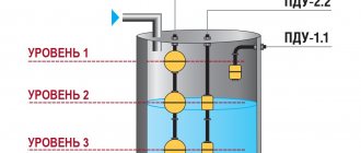
Float type overflow sensor
The simplest way to measure water level is using a simple mechanical design consisting of a sealed float, an oscillating lever or rocker and a shut-off valve. In this case, the sensor is the float, the ballast is the spring and the float weight, and the valve itself is the actuator.
In all float systems, the sensor or float is adjusted to a specific actuation height. The water rising in the tank to the control level raises the float and opens the valve.
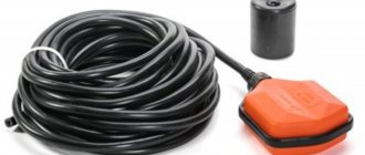
The float system can be equipped with an electrical actuator. For example, a magnet insert is installed inside a float sensor; when the water rises to the operating level, the magnetic field causes the vacuum reed switch to close the contacts, and thereby turns on or off the electrical circuit.
The float sensor can also be implemented in a free design, as, for example, in submersible pumps. In this case, the reed switch does not close under the influence of the magnetic field of the liner, but only due to the pressure difference inside the pump housing and at the level of the float. Today, a magnetic float sensor with an electric actuator relay is considered one of the safest and most reliable options for monitoring liquid levels.
Ultrasonic sensor
The design of the water sensor provides for the presence of two devices - an ultrasound source and a signal receiver. The sound wave is directed to the surface of the water, reflected and returned to the sensor receiver.
At first glance, the idea of using ultrasound to make a sensor for controlling the level or speed of water does not look very good. An ultrasonic wave can be reflected from the walls of the tank, refracted and interfere with the operation of the receiving sensor, and in addition, complex electronic equipment will be required.
In fact, an ultrasonic sensor for measuring the level of water or any other liquid is placed in a box slightly larger than a pack of cigarettes, and using ultrasound as a sensor provides certain advantages:
- The ability to measure the level and even the speed of water at any temperature, in conditions of vibration or movement;
- The ultrasonic sensor can measure the distance from the sensor to the water surface even in heavily polluted conditions with variable liquid levels.
In addition, the sensor can measure water levels located at significant depths, with measurement accuracy reaching 1-2 cm for every 10 m of height.
Electrode principle of water control
The fact that water is electrically conductive has been successfully used to make contact liquid level sensors. Structurally, the system consists of several electrodes installed in a container at different heights and connected into one electrical circuit.
As the container is filled with water, the liquid sequentially closes a pair of contacts, which turns on the pump control relay circuit. As a rule, the water sensor has two or three electrodes, so the measurement of water flow is too differentiated. The sensor only signals when the minimum level is reached and starts the pump motor, or when the tank is completely filled and turns it off, so such systems are used to control reserve or irrigation water tanks.
Capacitive type water sensor
The condenser or capacitive type of sensor is used to measure the water level in narrow and deep containers, this can be a well or a borehole. Using a capacitive sensor, you can determine the height of the water column in a well with an accuracy of ten centimeters.
The sensor design consists of two coaxial electrodes, actually a pipe and an internal metal electrode, immersed in the wellbore. Water fills part of the internal space of the system, thereby changing its capacity. Using a connected electronic circuit and a quartz oscillation coil, you can accurately determine the sensor's capacitance and the amount of water in the well.
Radar meter
A wave or radar sensor is used to work in the most difficult conditions, for example, if you need to measure the level or volume of liquid in a tank, an open reservoir, or an asymmetrical and irregularly shaped well.
The principle of operation is no different from an ultrasonic device, and the use of an electrical pulse makes it possible to perform measurements with great accuracy.
Hydrostatic sensor option
One of the options for a hydrostatic sensor is shown in the diagram.
For your information! A similar sensor is used in washing machines and boilers, where it is very important to control the height of the water column inside the tank.
The hydrostatic sensor is a box with an elastic spring-loaded membrane that divides the sensor body into two compartments. One of the sections is connected by a durable polyethylene tube to a fitting soldered into the bottom of the tank.
The pressure of the water column is transmitted through the tube to the membrane and causes the contacts of the starting relay to close; most often, a pair is used to start the actuator - a magnetic insert and a reed switch.
Non-contact (radar) level gauge
Continuous level measurement using the radar principle is based on the theory of propagation of electromagnetic waves by British physicist James Maxwell, created by him in 1865. He proposed that the changing magnetic field lines are surrounded by circular electric field lines, even in the absence of electrical conductors. Inspired by this theory, German physicist Christian Hülsmeier developed a telemobiloscope in 1904 in Düsseldorf and patented this first radar instrument. Thanks to this device, he became known as the inventor of the first radar.
Measuring principle
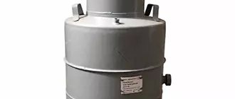
Measuring milk level in sterile storage tanks
The emitted signal is reflected from the surface of the medium being measured and is received by the antenna with a short time delay t. The radar principle used is called FMCW (Frequency Modulated Continuous Wave). FMCW radar measurements use a high-frequency signal whose emission frequency increases linearly during the measurement (so-called frequency sweep). The emitted signal is reflected from the surface of the measured medium and received with a short time delay t. The delay time is calculated by the formula t=2d/c, where d is the distance to the surface of the product, and c is the speed of light in the gas above the surface of the medium. Based on the frequency of the sent and received signals, the difference Δf is calculated, which is used in further signal processing. The frequency difference is directly proportional to the distance. A larger difference between frequencies corresponds to a larger distance, and vice versa. The frequency difference Δf is transformed into a frequency spectrum using a discrete Fourier transform (DFT), from which the distance is then calculated. The level is calculated as the difference between the height of the tank and the resulting distance.
Water pressure sensor
Hydrostatic pressure is determined under conditions where a flow or a certain volume of water is at rest. Most often, a hydrostatic sensor is used in heating and heating devices - boilers, heating boilers.
Water pressure sensor device
Such devices most often operate in trigger mode:
- When water pressure is high, the sensor closes the relay contacts and allows the pump or heater to operate;
- When the pressure in the sensor is low, even the physical ability to turn on the actuator is blocked, that is, no shocks or temporary surges in pressure will make the device work.
If the water pressure sensor is working properly, the sensor will give a signal to start the motor only if the load on the bellows remains for more than three seconds.
A typical smart sensor device is shown in the diagram.
The sensitive element of the system is a diaphragm connected to a bellows; the central rod can rise and fall depending on the pressure, and thereby change the capacity of the built-in capacitor.
Connecting the water pressure sensor
A simplified model of the sensor is used in home systems “hydraulic accumulator - well pump”. Inside the device there is a box with a membrane connected to a swing arm and two balancing springs.
The design is screwed onto the outlet fitting of the hydraulic accumulator. With an increase in internal pressure, the membrane rises and opens the main pair of contacts, so that the system responds properly to water pressure, the moment of turning off and turning on must be adjusted by the settling of the small and large springs in accordance with the readings of the dial pressure gauge.
Reed switch device
The main actuator element of the reed switch is the reed switch. The device is a small glass cylinder filled with an inert gas or with air evacuated. Gas or vacuum prevents the formation of sparks and oxidation of the contact group. Inside the flask there are closed contacts made of a ferromagnetic alloy of rectangular cross-section (permalloy wire) coated with gold or silver. When exposed to a magnetic flux, the contacts of the reed switch are magnetized and repel each other - the circuit through which the electric current flows opens.
Rice. 4 Appearance of reed switches
The most common types of reed switches operate on a closure, that is, when magnetized, their contacts are connected to each other and the electrical circuit is closed. Reed switches may have two terminals for making or breaking a circuit, or three if used to switch electrical current circuits. The low voltage circuit that switches the power supply to the pump is usually located in the control cabinet.
Water leakage sensor
Already from the name it becomes clear that we are talking about a device that detects the presence of water leaks from water supply lines. The operating principle of the device resembles an electrode system. Inside the plastic box, one or more pairs of electrodes are installed in a special pocket. In the event of an accident, water accumulating on the floor flows into the pocket and closes the contacts. The electronic circuit is activated, and based on the sensor signal, the electrically driven ball valves come into operation.
It is clear that the sensor itself is useless if it is used without a control system and automatic water shutoffs installed at the entrance to the house or on one of the water supply branches.
As an example, one of the most popular protection systems is the Neptune water leak sensor. The system includes three main blocks:
- The Neptune leak sensor itself is available in a wired or wireless version; the kit usually includes three separate sensors;
- Ball valve with electric drive, made in Italy, two pieces;
- Control unit "Neptune Base".
The most valuable part of the kit is the automatic taps; they are produced for installation on half-inch and inch pipe threads. The design can withstand pressure up to 40 Atm., and the Italian quality of the drive guarantees at least 100 thousand opening-closing cycles.
The sensor itself looks like two brass plates in a box, to which a low voltage voltage is applied with a very high input resistance; when the sensor is shorted, the current is limited to 50 mA. The design itself is made according to the IP67 protocol, therefore it is absolutely safe for humans.
Installation of wireless water leakage sensors
In the Neptune system, the sensor can be removed from the control unit at a distance of more than 50 m. In more advanced NEPTUN PROW+ wireless systems, instead of a wire system, water leakage sensors equipped with a WF module are used.
The control unit is equipped with a channel protected from interference and moisture, and an on/off system for ball valves. It is believed that no interference or random drops of moisture or condensation affect the operation of the sensors.
Boxes with a leakage sensor are installed no more than 2 m away from the pipes; the sensors cannot be shielded by metal plumbing fixtures or furniture.
Wireless water leak sensor
The design of a wireless meter is more complex than a conventional two-electrode version with a wired connection. There is a controller installed inside that continuously compares the current flowing between the electrodes with a reference value stored in memory. In this case, the reference value “dry floor” can be adjusted according to your own choice.
A very convenient solution, considering that the humidity level in the bathroom can be very high, and regularly occurring condensation can lead to false alarms.
As soon as the controller determines the level corresponding to flooding, the water control device sends an alarm signal to the base unit. The most advanced models are capable of duplicating a command via SMS message via GSM channel.
You might also be interested
The most sought-after characteristic of position sensors is their large operating range. Recent trends include support for connecting to standard networks and installing position sensors instead of limit switches.
In early June 2016, the Standards Group for Embedded Technologies (SGET) released a new specification, SMARC 2.0. congatec, the European leader in module manufacturing, has presented the first models meeting this specification. The modules are equipped with new Atom, Celeron and Pentium processors from Intel, codenamed Apollo Lake.
The First Moscow State Medical University named after I.M. Sechenov uses a video surveillance system consisting of 600 IP cameras controlled by the Macroscop software package.
Water flow sensor
In many cases, for stable and trouble-free operation of equipment, a water presence sensor is not enough; information is required about whether the flow is moving through the pipeline, what its speed and pressure are. For these purposes, water flow sensors are used.
Types of water flow sensors
In household and most simple industrial equipment, four main types of flow sensors are used:
- Pressure meter;
- Petal type sensor;
- Blade measurement scheme;
- Ultrasound system.
An outdated pitot tube design is sometimes used, but for reliable operation it requires at a minimum the absence of contamination and laminar water flow. The first three sensors are mechanical, so they are often subject to clogging or water erosion of the sensing element. The latest type of sensor, ultrasonic, is capable of operating in almost any environment.
The operating principle of an ultrasonic meter can be understood from the diagram. Inside the tube there is a wave emitter and a receiver. Depending on the flow speed, the sound wave may deviate from its original direction, which serves as the basis for measuring the flow characteristics.
Design and principle of operation
The simplest petal flow sensors work on the principle of a rowing oar. A petal suspended on a hinge is immersed in the flow. The higher the flow speed, the more the sensor lobe deflects.
More accurate vane sensors use an impeller or turbine made of polyamide or aluminum alloy. In this case, it is possible to measure the flow speed by the rotation frequency of the moving element. The only drawback is the increased resistance created by the petals and blades in the water flow.
The pressure sensor operates using dynamic flow pressure. Under the pressure of water, the movable element with a magnetic liner is squeezed upward, thereby freeing up space for the movement of liquid. The reed switch installed in the head instantly reacts to the magnetic field of the liner and closes the circuit.
Features of application
The use of ultrasonic meters has a number of features. For example, to eliminate measurement errors, you must follow the algorithm:
- carry out calibration of the device when the composition of the gaseous medium changes to establish the actual speed of sound;
- carry out calibration at each significant change in temperature, recording the speed values;
- In the future operation of the device when temperature changes occur, do not carry out calibration, but use previously recorded speed indicators.
The process of setting up the sensor is quite labor-intensive. A situation is possible when changes in the gas environment in the tank are not associated with changes in temperature. In this case, you will have to recalibrate the device.
DIY water level sensor
The simplest version of a device capable of signaling the filling of a tank or any other container with water is shown in the diagram below.
Structurally, the level detector consists of three metal electrodes mounted on a textolite plate. The circuit, assembled on a conventional low-power transistor, allows you to determine the maximum permissible upper and lower water levels in the container.
The design is absolutely safe to use and does not require any expensive parts or control devices.

