Ultrasonic weld inspection has been successfully used to identify flaws in welded joints since the 1930s. Over such a long period of time, scientists together with practicing specialists have developed various echolocation techniques. With their help, it is easy to identify violations in the integrity of the diffuse layer, deviations in the chemical composition of the surfacing, detection of slag, and oxide impurities. Ultrasound diagnostics (USD) is not inferior in accuracy to X-rays or radar. The device detects even the smallest defects that negatively affect the strength of the joint.
Among the non-destructive methods used today for determining weld defects, ultrasonic scanning has become the most effective and one of the most accessible that are put on stream. Based on the results of the inspection, a special log is kept for each welder. The scope of application of ultrasonic testing is limited exclusively to the geometric data of the workpieces. Welding seams of pipelines that experience high pressure are subject to diagnostics.
What is ultrasonic testing of pipeline welds
The method is based on the physical capabilities of ultrasound. Its peculiarity is that it is reflected from the boundary between media with different compositions. By its nature, ultrasound is an elastic mechanical vibration, which is generated by various methods. Its sound range is beyond the reach of the human ear. The emitters do not have a harmful effect on the human body.
Ultrasound diagnostics are performed in a wide frequency range: from 20 kHz to 500 MHz. Waves directed from the emitter in any direction propagate at the same speed, provided the medium is homogeneous. When the environment changes, they are refracted or reflected, like a ray of light. The speed of a longitudinal wave is almost twice that of a transverse wave.
The sensitivity of devices depends on its design features and varies greatly. The wide range is explained by the fact that the generated waves can only be reflected from those defects that are equal to or greater than the wavelength. Ultrasound perfectly detects small defects in a welded joint, namely: voids, cavities, various types of inclusions, slag, grains and other impurities that reduce the strength of the seam.
General information
There are several methods for detecting defects in pipe welds:
- magnetic;
- acoustic;
- electric;
- optic.
Their task is to determine the tightness of the joints, the strength of the metal in the seams, whether there are stresses and other parameters that determine the reliability of the pipelines. At the same time, flaw detection methods are almost the same for all types of pipelines: heat, gas, water, oil pipelines.
Flaw detection of pipelines
All of the methods mentioned above belong to the category of “non-destructive” technologies. That is, flaw detection is carried out directly on the construction site. Pipe joints are not destroyed, which reduces the cost of installation work.
Pipeline flaw detection is based on a scanner called a flaw detector. Each technology has its own operating principle for this equipment. The most effective flaw detectors:
- eddy current;
- ultrasonic;
- magnetic powder;
- capillary.
Advantages and disadvantages of ultrasonic flaw detection
Important advantages:
- non-destructive method of quality control of welded joints. There is no need to cut out a part of the metal structure and take it to the laboratory for research;
- flaw detectors are universal. They are suitable for use in the field or in an equipped laboratory;
- the method is equally well suited for determining defects in both homogeneous and dissimilar compounds;
- it does not take much time to determine the condition of the seam. The result is ready literally immediately;
- The devices are absolutely safe to use. They do not have a harmful effect on the human body;
- Most types of defects can be diagnosed. The reliability of the results obtained is very high.
The disadvantages of the equipment are related to the limitations of its use and the need to train specialists to operate the equipment. The fact is that the ultrasonic signal is attenuated in coarse-grained structures. It is necessary to use special converters with a specific radius of curvature of the sole.
Results Evaluation Options
The quality of the work performed is directly affected by the sensitivity of the device, which allows you to accurately recognize the parameters of the defect. First of all, using an ultrasonic flaw detector, the number of flaws that can lead to destruction of the weld and the entire metal structure as a whole is determined. The assessment of defects located in the weld is carried out according to the following criteria:
- acoustic wave amplitude;
- conditional wave length;
- size of the defect and its shape.
To determine the length of the wave and the width of the defect, it is necessary to carefully move the emitter along the weld joint. To determine the height of an internal crack or cavity, it is necessary to take into account the time intervals between the reflected and emitted waves. It is worth noting that the process of identifying the form of a defect requires a highly qualified operator, so it is better to entrust this work to specialists who have undergone appropriate training.
Types and methods of ultrasonic testing of welded joints
To diagnose joints with ultrasound, different methods are used:
- straight beam;
- single reflection;
- double reflection;
- multiple reflection.
Regarding the direction of the beam, it is selected along the normal, where the risk of defects is especially high. The most common measurement options:
- pulse echo diagnostics . The device generates a wave and is configured to receive a call. If it is not there, it means that no defects were detected. If the result is the opposite, then there is a separation of media in the mass under study;
- echo-mirror . Involves the use of a wave-generating sensor and a catcher receiver. Placement of devices is at an angle to the axis of the joint. The receiver catches all ultrasonic radiation and uses it to diagnose cracks or their absence;
- shadow diagnostics . The waves travel across the entire joint area. The receiver is located behind the weld joint. In the case when the radiation is reflected and does not reach the receiver, a shadow area is recorded;
- mirror-shadow flaw detection . The technology combines shadow and mirror research methods. A set of sensors is used that detect reflected sound vibrations. If there is a clean wave, this means that the seam has no defects;
- The delta method involves exposing an object to a directed beam. By the reflection of the sound signal, flaws in the joint are determined. When there is a need to obtain accurate results, you can use fine-tuning diagnostic equipment.
In practice, problem areas of welding are most often identified using pulse echo and shadow diagnostics. The non-destructive testing method makes it possible to identify a defective section, which over time can lead to depressurization of the weld. This is an excellent method for preventing accidents. Especially when it comes to high pressure lines.
Results
Metal degradation is a serious problem, especially in structures in which various media move under high pressure. Over time, the strength of the connecting areas decreases, which can lead to serious consequences. The problem today is solved simply - by control, for which various methods of pipeline flaw detection are used.
Each of the above methods has its pros and cons. But they guarantee high detection accuracy, which is required during control inspections. Therefore, newly introduced pipelines are subject to mandatory inspection. Operated ones are checked according to a strictly approved schedule of preventive maintenance. It is impossible to violate the deadlines for flaw detection under any pretext.
Ultrasonic flaw detection of a weld: video.
What do you think, which of the proposed methods is the most informative? Write in the comments. Save the article to bookmarks and share it on social networks.
Ultrasonic testing technology: area of use
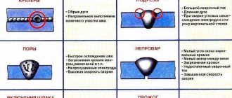
Ultrasonic testing is used to inspect welds of non-ferrous metals, carbon and alloy steel, and cast iron. Using diagnostic equipment, the following is detected:
- porosity formed by atmospheric gases;
- rust inside the solidified melt;
- uncooked areas;
- violation of geometry in certain areas;
- cracks;
- inclusions of foreign bodies and other differences in structure;
- delamination;
- folds formed by fusion;
- cross-cutting defects;
- non-joint sagging of the diffuse layer.
Using ultrasonic testing, connections of a wide variety of structural elements are monitored:
- flange, pipe and other ring connections;
- tee seams;
- joints, regardless of their configuration (including complex shapes);
- transverse and longitudinal seams that experience high pressure or multidirectional loads.
When passing through a metal grille, sound waves are scattered. This property imposes certain restrictions on the scope of use of the equipment. All of them are set out in the manufacturer's instructions, which are included with the device.
Geometric limitations:
- the thickness of the workpieces being tested cannot be more than 50-80 cm, or less than 8-10 mm;
- distance to the control object: minimum – 3 mm, maximum – 10 meters.
The technique has proven itself well in construction and mechanical engineering; at enterprises with high pressure lines.
Equipment selection criteria
The choice of a television inspection system is made taking into account the characteristics of the objects at which they will be used, as well as the operating characteristics of various types of equipment. Let's consider typical areas of application, operating features, advantages and disadvantages of devices used for video diagnostics of pipelines.
Self-propelled robots - carts.
One of the main technical characteristics of such devices is the minimum and maximum limits for the diameters of the pipes or collectors being examined. The smallest pipe size is determined by the dimensions of the trolley, the largest depends on the presence of structural elements that ensure positioning of the video camera in height near the axis of the pipeline (large-diameter wheels, spacer bushings for wheels to widen the track, a mechanism for lifting the video camera, etc.), as well as on such parameters , such as the brightness of the backlight sources, the sensitivity and resolution of the camera, the presence of the zoom function and other options. The modern market offers robots of various sizes and manufacturers, capable of working in pipes with a diameter of 100 to 3000 mm.
The second important characteristic of the robot is the depth of examination, that is, the distance to which it is able to move in the pipe. On the one hand, the distance is determined by the length of the cable, that is, it is necessary to select a drum of the required capacity. On the other hand, the maximum value of the robot’s path is determined by the weight of the robot, which ensures adhesion of the wheels to the surface of the pipe, the material and shape of the wheels, the presence of treads and lugs, the power of the electric motor and the specific gravity of the pulled cable, since as the distance traveled increases, the frictional resistance of the cable against the pipe walls increases .
Pushed modules.
This teleinspection system is mainly used to inspect pipelines with a diameter of 100 to 400 mm. The minimum diameter value depends on the size of the chamber. When working in large diameter pipes, the guide rod may twist during the pushing process, making further advancement impossible. The maximum pushing length of the module depends on the elastic properties of the rod, which are determined by the material of the rod and its diameter. For example, to push a camera to a distance of 30 - 50 meters, the diameter of the rod must be at least 7 mm, but if you need to examine 60 - 80 meters of the intra-pipe space, you should use a rod with a thickness of 9 mm or more.
Floating modules.
A teleinspection system of this type is unrivaled when it is necessary to conduct a video inspection of a free-flow pipe or collector with a level of filling with wastewater of 300 mm or more. A positive quality of a floating camera for television inspection is the ability to inspect large-diameter collectors without complex measures to stop the flow. The downside is the narrow scope of application - only non-pressure, partially filled drains.
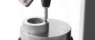
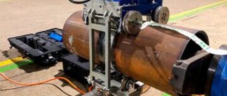
Ultrasonic flaw detector device
Each device has an ultrasound emitter, amplifier and receiver. The main difference between the different models is the type of generator. Piezoelements are the most widely used. The sensor sends signals at regular intervals.
The pauses between pulses are several microseconds. Their duration is set by the user, taking into account the desired defects, density and structure of the metal. The reflection reveals the defect and its main parameters: size and depth of location. The emitter is placed in a dynamic probe, which moves along the seams being examined.
The accuracy of the device depends on the sensitivity of the receiver, which detects the reflected wave. It is important for the user to take into account the fact that the wave changes direction at the boundaries of the media. Things are easier with the definition of shadow areas - in these places the wave is reflected. The device catches the sound signal, converts it into electricity and displays it on an oscilloscope.
Research stages
In-line flaw detection takes place in several stages. This:
- The preparatory stage is diagnostics.
- Cleaning the internal space of pipes from foreign objects.
- Carrying out calibration, ensuring normal cross-country ability.
- Inspection by a profiler - study of bends, turns, defects.
- Examination with ultrasonic and magnetic in-line devices that detect cracks, corrosion and other inconsistencies.
- Calculation of residual life, determination of safety.
There are a number of in-pipe flaw detection techniques.
Critical angles
When performing ultrasonic testing, the operator needs to select the type of transducer, calibrate and configure the device for the expected defects of the object. Critical angles of incidence (longitudinal and transverse) must be taken into account when ultrasound passes through solid surfaces of materials.
The first critical angle is the smallest angle of incidence of the longitudinal wave at which the refracted ray does not cross the boundary of the second solid medium. For example, for the plexiglass-steel boundary it is 27.5º.
We recommend reading Features of welding mixtures and their use
The second critical angle is considered to be the smallest angle of incidence of the longitudinal beam at which refraction does not penetrate through the boundary into the second solid medium and internal damage is not detected. For plexiglass-steel it is 57.5º.
The third critical angle is the smallest angle of incidence of the transverse beam at which there is no reflected longitudinal wave. The beam travels along the surface of the object without recognizing defects inside it. To cross the steel-air boundary, the angle is 33.3º.