GOST 18353-79 “Non-destructive testing. Classification of types and methods”, depending on the physical phenomena underlying non-destructive testing, divides it into types:
— optical; — radiation; — acoustic; - magnetic; — eddy current; - electric; - radio wave; — thermal; - penetrating substances.
Type of control is a conditional grouping of non-destructive testing methods, united by the commonality of the physical principles on which they are based. Methods of each type of non-destructive testing are classified according to certain criteria:
— the nature of the interaction of physical fields with the object; — primary informative parameters; — methods of obtaining primary information.
Methods for quality control of welded joints are established by GOST 3242-79.
The use of a method or set of control methods for detecting defects in welded joints when inspecting structures during their manufacture, repair and reconstruction depends on the requirements for welded joints in the technical documentation for the structure. The technology for monitoring welds by any method must be established in the regulatory and technical documentation for monitoring.
Content
- Features of choosing a non-destructive testing method
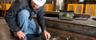
- Visual and measuring control of welding by external inspection
- Ultrasonic flaw detection of welds
- Magnetic flaw detection of welded joints
- Radiographic testing with X-rays and gamma rays
- X-ray control
- Gamma radiation control
- Video: non-destructive testing methods
Non-destructive methods for testing welded joints include external inspection and various types of flaw detection. Non-destructive testing is based on obtaining information about the materials being tested using electromagnetic and acoustic fields, as well as from various substances penetrating into the metal of the product.
To identify internal weld defects, X-ray flaw detection, gamma radiation flaw detection, ultrasonic flaw detection, magnetic flaw detection methods (for example, magnetic particle flaw detection), weld permeability testing (including the capillary flaw detection method), and vacuum flaw detection are widely used.
Penetrant Control Methods
Penetrant flaw detection
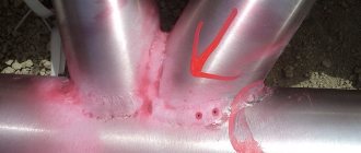
Capillary NDT methods are designed to detect open defects that appear on the surface: cracks, pores, cavities, lack of fusion and other discontinuities in the surface of products without destroying them. There are two main methods of penetrant flaw detection: color and fluorescent. These methods are used to control parts of various shapes made of austenitic, titanium, aluminum, copper and other non-magnetic materials. These methods allow you to identify:
— welding, thermal, fatigue cracks; - porosity, lack of penetration and other defects such as open discontinuities of various localization and extent, invisible to the naked eye and lying within the sensitivity and reliability of flaw detection tools.
Leak detection
Bubble method using vacuum chambers
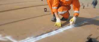
Vacuum testing of welds is used in cases where the use of other methods is for some reason excluded. In particular, this method is widely used in the inspection of welded bottoms of tanks, gas tanks, cisterns, and waterproofing boxes. It allows you to detect individual pores with a diameter of up to 0.004-0.005 mm, and the productivity when using it reaches 40 - 60 m of welds per hour. The vacuum is created using a portable vacuum chamber, which is installed on the most accessible side of the seam section being tested, previously generously moistened with a soap solution. As a result of the pressure difference on both sides of the seam, air will penetrate into the chamber if there are leaks in the welded joint. In places of cracks, lack of penetration, and gas pores, persistent soap bubbles form, clearly visible through the transparent top of the chamber. Having marked the location of the defects with chalk, colored pencil or paint, atmospheric air is let in, the chamber is removed and the marks made are transferred to the weld.
Inspection of seams using gas-electric leak detectors
Currently, two types of gas-electric leak detectors are used: helium and halogen. The sensitivity of gas-electric leak detectors to detect leaks in seams is very high, but due to the complexity of the design and the significant cost of manufacturing, they are used only for monitoring particularly critical welded structures.
The operating principle of a helium leak detector is based on the high ability of helium, at a certain vacuum, to pass through leaks in welds. During testing, the welded seams on the outside of the container being tested are blown from a rubber hose with a thin stream of helium under low pressure in a special vessel - a gasometer. If there are leaks in the seams, helium or its mixture with air flows from the container into the mass spectrometric chamber, in which a high vacuum is maintained. When helium enters the mass spectrometric chamber, an ion current appears in it, which is supplied to indicators - a milliammeter and a siren. The amount of deflection of the milliammeter needle allows one to judge the size of the defect.
Weld density testing
Density tests are carried out on containers for fuel, oil, water, pipelines, gas tanks, steam boilers, etc. There are several methods for monitoring the density of welds: hydraulic test, water test without pressure or in bulk, water jet or spray test, pneumatic test, ammonia test , kerosene test.
Features of choosing a non-destructive testing method
The choice of the optimal non-destructive testing method depends on the following factors:
1. On the physical properties of the metal being tested 2. On the thickness of the welded joint 3. On the type of welded joint and its thickness 4. On the condition of the joint surface 5. On the manufacturing features of the welded structure 6. On the technical and economic indicators of the testing method and other factors.
A characteristic feature of most non-destructive testing methods is that defects are detected only indirectly, as a result of the analysis of certain physical properties of the welded joint, which do not affect the performance of the product.
For example, during radiation flaw detection, defects of the “continuity” type are determined by the intensity of ionizing radiation passing through the seam. The results of such control methods are often difficult to decipher, so they must be carried out by qualified personnel.
Since among the existing control methods there is no universal one that would guarantee the detection of all defects, it is important, first of all, to detect unacceptable defects. Each method has its own advantages and disadvantages. In most cases, several methods are used. This approach allows you to detect a defect with a high degree of probability. Next, we will consider each of the control methods separately.
How is permeability checked?
When containers, pipelines, and so on are welded, it becomes necessary to assess what the tightness is. Such quality control is also carried out using various methods and tools:
- Hydraulics and pneumatics tests.
- Bubble method.
- Leakage.
And so on. Pneumatic testing is when large quantities of water or gas are released into a pipeline. The foaming composition is applied to the surface from the outside. If foam bubbles appear, it means the seal has been broken.
Video
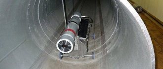
ERW-pipe welding machine for field application - Equipment for welding and non-destructive testing.
Visual and measuring control of welding by external inspection
External inspection can only reveal external defects in the weld. Inspection can be done both with the naked eye and with the help of a magnifying glass with multiple magnification. The dimensions of the welds are checked using templates and measuring tools.
External inspection is usually applied to all welds, regardless of the degree of structural responsibility and whether other inspection methods are used. More details about this control method are described on the page: “Control of welds by external inspection and measurement.”
Rules for external and technical inspection
Any pipeline quality check begins with an external inspection. It is not only purely visual, but also involves the use of measuring and other types of technical instruments. This will allow us to identify problems in external factors, compliance of the current state with standards and legal requirements.
Video
Section II Lesson No. 5. Carrying out control.
Detecting even small cracks in welded joints will not be difficult if you clean a small area on the seam and then treat it with alcohol or a weak acid solution.
Geometric dimensions cannot be determined without a ruler and caliper. Good lighting will make inspections more efficient. As does using a magnifying glass that supports 8-10x magnification.
Ultrasonic flaw detection of welds
The ultrasonic flaw detection method is based on the property of ultrasonic waves to pass through a large thickness of metal and be reflected from accumulations of slag, non-metallic inclusions and other defects in the weld.
Ultrasonic flaw detectors operate on the following principle: a plate of quartz or Rochelle salt is exposed to a high-frequency electric field. Under the influence of the field, the plate emits ultrasonic waves, which are directed to the welded joint.
At the boundary between the homogeneous metal and the defect, ultrasonic vibrations are reflected, and the reflected wave is perceived by the second plate. Under the influence of the reflected wave, a variable potential difference is formed on this plate, the magnitude of which depends on the intensity of the reflected wave.
Next, the electrical vibrations emanating from the plate are amplified and transmitted to an oscilloscope. On the oscilloscope screen, the pulses of the wave directed to the weld and the wave reflected from the defect in the weld are simultaneously displayed. The location and nature of the weld defect is determined by the location of these pulses.
The ultrasonic flaw detection method allows you to identify all known defects in welded joints. This non-destructive testing method is described in more detail in the article: “Ultrasonic testing of welds. Ultrasonic flaw detection".
Technology selection
If you want to establish control of welds, you need to realize that the choice of a specific technique depends on many factors.
- Product output volumes. No matter how accurate the data obtained, it is simply unprofitable to use time-consuming verification methods for large-scale production. With its help, only selective control is possible, and it does not always give an objective picture. At the same time, in pilot, piece or small-scale production, the speed of control is not critical. When the cost of the final product is high and its quality is critical, it makes sense to spend time on the most thorough inspection.
- Required accuracy of measurements. For products where the tightness of the welded joint is not important and do not experience high loads, it is sufficient to obtain general information. This applies to household appliances, simple building structures or light industrial products. In cases where the tightness of the seam is important, preference should be given to methods that detect even the slightest leaks in the joints. To examine parts under high loads, it will be necessary to use technologies that can give the most complete picture of the internal structure of the weld. After all, hidden defects that appear after some time often become the cause of serious man-made disasters. In this regard, non-destructive testing of pipeline welded joints poses a separate problem. Thousands of kilometers of highways along which water flows and liquid or gaseous fuel moves can be taken out of service due to a crack invisible to the eye. The rupture of pipes through which chemically aggressive substances are pumped in production workshops is unacceptable, as it is quite capable of leading to human casualties.
- Features of production. When analyzing welded joints of electronic components, the heating of which is unacceptable, and the size of the parts is small, it is necessary to abandon many effective flaw detection methods in favor of, albeit not so reliable, but better suited for solving the problem. Other problems have to be solved where the length of the seams is many hundreds of meters. When laying gas pipelines or building ships, it will not be possible to use equipment that works successfully in a scientific laboratory.
- Materials used. In modern production, various parts and alloys are used. They all have their own characteristics, differing in internal structure, magnetic properties, reaction to temperature heating or pressure. All this should be taken into account when choosing a control method. After all, a technique that has proven itself well when checking the quality of welds on products made of steel may be ineffective for flaw detection of parts made of aluminum.
Magnetic flaw detection of welded joints
The essence of the magnetic flaw detection method is to excite a non-uniform magnetic field passing through the welded joint with the formation of scattered magnetic fluxes in areas containing welded defects.
There are several methods of magnetic testing: magnetic particle flaw detection, magnetographic testing and induction testing. Magnetic particle flaw detection is the simplest of them, but the reliability of control of this method is lower than that of others.
In magnetic particle flaw detection, the joint being tested is magnetized, magnetic powder (iron scale or fine iron filings) or a suspension is applied to its surface, and a magnetic field is passed through the joint. Magnetic powder or suspension, under the influence of a magnetic field, will be distributed evenly. But in places where defects are located, accumulations of magnetic powder (suspension) will be observed.
During magnetic testing, the magnetic field passed through the welded joint is recorded on magnetic film. To do this, a magnetic film is applied to the connection while a magnetic field passes through it. Next, using magnetic flaw detectors, I read the recorded information from the film and convert it into sound or into an image on the monitor of the flaw detector. In addition to these methods, there is an induction method of magnetic flaw detection.
More detailed information about these control methods can be found on the page: “Magnetic methods for testing welds. Magnetic flaw detection of welding.”
What is it needed for
Non-destructive testing methods of welded joints are used to detect defects on the surface and in the thickness of the product being tested, as well as to determine their spatial position, size and shape. In this case, the integrity of the products is not compromised.
Based on thermodynamic characteristics, non-destructive flaw detection methods are divided into types:
- related to the application of energy transmission;
- using the movement of matter.
Radiographic testing of welded joints. X-ray and gamma ray control
X-ray control
X-rays propagate differently in different materials. For example, such rays will pass differently through a homogeneous metal, through slag inclusions, or through a void in the metal. The X-ray flaw detection method is based on this property of X-ray radiation, the diagram of which is shown in the figure.
To control the weld, a radiation source is installed on one side and a detector on the opposite side. X-rays, passing through the seam from the source, irradiate the detector (photographic film or photographic paper), which displays a complete picture of the passage of the rays through the metal. The presence of darkened areas on the film indicates that the intensity of the rays in these areas was high, therefore, there are defects in these areas of the welded joint. For more complete information about this non-destructive testing method, see the page: “Radiographic method of testing welded joints Part 1 X-ray testing.”
Gamma radiation control
Gamma ray inspection, like X-ray inspection, is based on the ability of gamma rays to pass differently through metal, non-metallic inclusions, and voids in metal.
The gamma control scheme is as follows: from an ampoule containing radioactive isotopes, a stream of gamma rays is directed to the controlled connection. On the reverse side of the connection there is a cassette with film or photographic paper, which displays a complete picture of the passage of rays through the metal. In places where defects are detected, darkened areas will appear on the film. In order to regulate the flow of radioactive radiation, the ampoule is placed in a lead container with a small hole through which the flow of gamma rays exits.
Radiation flaw detection has advantages over x-ray scanning. For example, gamma rays have greater penetrating power, which allows them to be used when inspecting large metal thicknesses, more than 300 mm thick. In addition, gamma radiation control is more cost-effective because has a lower cost. But, it also has its drawbacks. For example, radiation poses a great danger to human health. More details about this method of welding control are described on the page: “Radiographic method of testing welded joints Part 2 Radiation testing by gamma radiation.”
Quality control of welded joints and the need for it
When welding work is carried out on pipelines, the occurrence of defects cannot be avoided. In turn, these shortcomings have a negative impact on the appearance of welded joints, their technical characteristics, and reliability. In total, there are two types of damage: weld formation and metallurgical type defects.
The formation of a structural seam leads to the appearance of metallurgical flaws. They usually appear while the material is cooling or heating. The second group of damages is caused by non-compliance with standards during work.
It is necessary to identify the following types of deficiencies in advance. They all negatively affect the quality of the entire pipeline in the end.
- Disturbances in the metal microstructure. This leads to an increase in the oxide content and the appearance of coarse grains and grains with oxidized edges.
- Presence of gas inclusions or pores. They can be grouped or individual, sometimes they look like bridges. Or they come to the surface. Then they are called fistulas.
- Impurities with slag inside the seams. Because of them, the product loses its original strength.
- The occurrence of cracks of various types is typical for areas with seams and heat-affected areas. The differences lie in size.
- Group of incomplete preparations. This is the name given to local areas of a seam where there is no adhesion to the base material.
- Burns or holes in welds that appear when melt flows out during welding.
- Undercuts. The name for grooves in the longitudinal plane at the boundaries with seams, the surface of the base metal.
- Irregularities in the shapes and sizes of seams.
Only if each of the defects is identified can the reliability of the pipeline be guaranteed at the maximum level.
A thorough assessment of how such flaws affect the design must be carried out. Otherwise, it is impossible to correct the situation before the pipeline begins operation.