Threaded connections are very widely used in mechanical engineering, so the tool for making threads is one of the most common.
Threads are distinguished:
- according to the location of the turns - external and internal;
- in the direction of the helix - right and left;
- according to the profile shape of the grooves - triangular, trapezoidal, rectangular, thrust and special;
- in the direction of the generatrix - cylindrical and conical;
- according to the size system - metric and inch.
Depending on the size of the thread, the type of production and the design of the parts, different types of thread-cutting tools are used:
- thread cutters (rod and shaped single-thread and multi-thread);
- taps (hand, machine, nut, machine, tool, master, etc.);
- round dies;
- threading heads;
- thread cutters.
Mechanics of the process: we study in detail
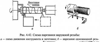
Try to imagine what happens to the metal of the workpiece at the beginning of the movement of the threading tool. Its first few turns converge into a cone, forming the lead-in part. A little force is enough for the sharp and hard teeth of a die or tap to press small grooves into the metal and become firmly fixed in it.
That's it, now the tool, as they say, has “taken a step” and will precisely follow the spiral of the thread, becoming stronger the more turns there are. But the fact is that metal cannot deform indefinitely. If the tool's teeth cut too deeply, they will push out excess material, creating chips. If you cut a hole with a regular hardened bolt, chips will clog the newly cut thread and the tool will have to be constantly unscrewed to clean the hole. The tap and die have special grooves for chip removal.
It is very important to understand that the teeth of the working part do not cut grooves in the metal. They push them, squeezing out the metal on both sides of them. Removal of excess is carried out by a notch between adjacent teeth: it gives the ductile metal a shape, and the remainder is thrown into the chip groove.
Drilling holes and pre-processing bars
From the last observation we can conclude that the outer diameter of the thread is slightly larger than the original diameter of the rod on which it is cut. Likewise, the axial distance between the tips of the internal threads will be slightly less than the hole.
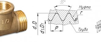
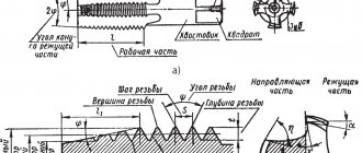
If you look at any drawing depicting a metric thread, you can note a number of key dimensions:
- Inner and outer diameter. These values change names depending on whether the thread is internal or external.
- Thread pitch is the distance between the tops of adjacent teeth.
- Shape and dimensions of the nominal profile, angles of inclination.
So: the diameter of the rod or thread hole is not equal to either the external or internal diameter of the thread. The easiest way to determine the hole size for an internal thread is to subtract the pitch distance from the outer diameter. For external threads, the same value must be added to the diameter of the rod.
However, real professionals always use tables of standard metric threads, where the recommended diameters also take into account the type of thread, the characteristics of metals and their alloys. So the main problem is finding the right rod or drill.
You set the basis for high-quality cutting at the stage of drilling or preparing the rod. The hole must be drilled strictly perpendicularly; among the ways to control the right angle, you can suggest combining the drill with the reflection in a placed mirror or placing a credit card nearby.
Rust should be removed from the rod and the side surface should be checked for evenness with a metal ruler. The best way to prepare the rod is to clamp it into the drill chuck and give the edge a good file. When rounding, it is allowed to grind the rod down a couple of tenths if this is necessary for alignment, which in practice is more important than the completeness of the cutting.
This is of little use when working with fixed rods. You have to select the thread diameter according to the diameter of the rod, choosing a value less than the recommended one. For a more convenient approach at the end, you need to remove the chamfer and perform the cutting especially carefully and accurately. Do not forget to generously apply machine oil to the area to be treated.
Cutting in several passes
Threads are usually made in several passes, using taps with different profile completeness. The main difficulty lies in the starting, setting pass. It is made with a tap with one thin groove on the shank. The tool must be inserted freely into the hole and, pressing it with a little force, turn it a couple of turns. In this case, the perpendicularity of the insertion is controlled by a credit card; small deviations of 5–7° are quite acceptable.
In 5–6 turns, the lead-in part is completely inserted into the hole and the tap confidently begins to move. Now the tool must be rotated without pressing force. It would be a mistake to correct minor deviations from perpendicularity at this stage - the tap is not to blame for this, it goes strictly along the hole. After every 1.5–2 feed turns, you need to unscrew the tool half a turn.
After the starting pass, when the thread profile is 50–60% ready, it should be formed with medium (#2) and finishing (#3) taps with the corresponding number of grooves on the shank. Here it is only important to check that the tap fits correctly onto the existing thread; the rest is a matter of technique.
There are practically no special features of working with the die; the greatest difficulty is working on the lead-in part. The die is short, only 2.5–2 turns, so it is recommended to hold the tool with both hands.
Methodological development of a practical lesson “Cutting fastening threads with taps and dies”
Methodological development of a practical lesson
OGBPOU "Ulyanovsk Technical School of Instrument Engineering"
Group No.69
Profession
General machine operator
Master of industrial training
Trunov V.N.
Topic of the program:
“
Processing of parts on screw-cutting lathes”
Lesson topic
: “Cutting fastening threads with taps and dies”
Lesson objectives:
educational:
- consolidate students’ knowledge of safety precautions;
- to form in students concepts about “threads”, “their image”, “designation”, “technology for cutting threads on standard parts”;
- study the requirements of thread standards.
developing:
- distinguish between thread profile, profile angle, thread stroke, thread pitch on fasteners;
- analyze and eliminate possible causes of defects when cutting threads on fasteners.
educational
- create a conscious need for work;
- cultivate initiative and independence in work activities;
- instill the skills of caring for tools and equipment;
- create a sense of collectivism and mutual assistance.
Teaching methods:
explanatory and illustrative with elements of conversation, practical and demonstrative.
Lesson organization form
: group.
Intersubject communication
: materials science, tolerances and fits, general course in turning.
Material and technical base :
equipment (screw-cutting lathe models; cutting tools; control and measuring tools; finished product - standard, blanks.
PROGRESS of the practical lesson
1.Organizational part (5 minutes).
1.1. Check the attendance of students using the log.
1.2. Check the appearance of students (workwear).
2.Introductory briefing (40 minutes).
- Inform the topic of the program.
- Inform the topic of the lesson.
- Communicate the educational purpose of the lesson.
2.4.Updating the basic knowledge of students.
- Conduct a survey (front form) on the material covered in previous classes:
- What are the technical requirements for the threaded surface and the part?
- What types of threads are considered fastening threads?
- What is the purpose of the thread?
- What are the main elements of carving?
- How are threads indicated on drawings?
- What types of defects when cutting threads with cutters do you know?
- How is thread inspection performed?
- Decipher the thread designation in the drawings:
- M20 – 7h 6h
- M30 x 1.5LH – 5H6H-25
- Types of threads based on the number of starts in the direction of the turns?
2.5. Showing students how to drill holes on a lathe.
2.6
.
Explanation of new material:
2.6.1. Story using information technology.
Thread cutting is called the formation of threads by removing chips from the external or internal surfaces of workpieces.
Threads on parts are obtained by cutting on drilling machines, lathes,
thread-cutting and manually. Internal threads are cut with taps, and external threads are cut with dies.
2.6.2.For cutting external threads, dies are used
. The cutting edges formed by longitudinal holes have a wedge shape at the intersection with the thread profile and ensure cutting of the workpiece.
To cut a thread with a die on a rod, it is necessary to determine the diameter of the rod using the table and grind the workpiece to this diameter with the obligatory chamfering.
| Thread diameter, mm | 3 | 4 | 5 | 6 | 8 | 10 |
| Rod diameter, mm | 2,9 | 3,9 | 4,8 | 5,8 | 7.9 | 9,9 |
Diagram of thread cutting with a die on a screw lathe: 1 – three-jaw chuck; 2 – workpiece; 3 – die holder with die; 4 – tailstock quill; 5 – bar; 6 – tool holder
When cutting threads with a die on a lathe, it is necessary to install the die holder body into the tailstock quill and rest the handle on the surface of the upper part of the support; Rotate the tailstock handwheel to feed the die onto the rotating part until it is completely screwed onto the workpiece. It is recommended to cut several threads by hand and only then turn on the machine.
The cutting speed should be: for steel 3-4 m/min; for cast iron - 2.5 m/min; for brass 9-5 m/min. When cutting, it is necessary to use appropriate cutting fluids.
2.6.2.Taps are used to cut internal threads.
Taps, according to their intended purpose, are divided into hand-held and machine-made - hand-held and machine-made and consist of a working and tail part with straight and helical grooves. The working part of the tap consists of an intake and a calibrating part. The cone-shaped fence part does the main work. Calibrating - directs the tap into the hole. Grooves - recess (for removing and placing chips.)
The cutting edges of the teeth are wedge-shaped. Tap - 1 (rough); 2 (medium) and Z (finish) on the shank indicate the thread size. Combined taps consist of 2 parts: 1 part for preliminary, and 2 for final (finishing). The collars (square) are adjustable.
Scheme of cutting internal threads with a tap.
The selection of drills for drilling holes for threads is determined according to the table. After drilling, the workpiece is secured in a vice vertically along the square, then the driver is pressed against the tap with the left hand. With the right hand, turn it to the right until the tap cuts into the metal on several threads and takes a stable position, after which the driver is taken by the handle with both hands and rotated with the hands intercepted every half turn. Rotate 1-2 turns to the right and 0.5 turns to the left (the chips break).
2.6.4. Thread control
. The thread pitch is measured with a thread template, which is a plate 2 on which teeth are applied with a thread pitch indicated on the template plane. A set of templates for metric or inch threads is fastened into cassette 1. Thread templates are used to determine only the thread pitch.
The correctness of internal and external threads made on a part is comprehensively assessed using thread gauges. Thread gauges are divided into go-through gauges, which have a full thread profile and are, as it were, a prototype of a threaded connection part, and non-go-through gauges, which control only the average diameter of the thread and have a shortened profile.
To measure the outer, middle, inner diameters and thread pitch, thread micrometers are used. A thread micrometer has mounting holes in the spindle and heel into which sets of replaceable inserts are installed that correspond to the thread elements being measured. For ease of measurement, a threaded micrometer is fixed in a stand and then adjusted according to a template or standard.
Before testing, the parts being tested must be cleaned of chips and dirt. During the inspection process, you should handle the gauges carefully so that nicks and scratches do not appear on their working threaded surface.
2.6.5.Labor safety when cutting threads
. When cutting threads with a die and tap on a machine, you should use labor safety rules when working on lathes. If the tap breaks, remove the fragment from the hole with pliers or a hand vice. The shavings are swept away only with a brush.
2.6.6. Demonstration by the industrial training master of labor techniques for cutting external and internal threads, preventing possible errors when performing the work
:
- sequence of setting up a machine for cutting external and internal threads;
- dangerous cutting zones;
- fastening thread cutting technology;
- self-control techniques during the manufacture of parts.
2.6.7. After demonstration and reinforcement, repetition of TB:
While working on the lathe:
- attention is paid to cutting tools and devices;
- special attention to the set cutting speed.
The work is carried out strictly according to the requirements of the technological process and always with cooling.
Careful handling of cutting and measuring tools and equipment is necessary.
2.6.8.Repetition of covered material
(frontal survey)
1. Where are threaded connections used?
2. How is a bolt different from a stud?
3. What tools are used to cut external threads? Internal thread?
4. What do a die, a tap, a cutter, and a drill have in common?
5. What is the purpose of the grooves in the die and tap?
6. In what sequence are threads cut on a rod by hand? In the hole?
7. Why is the thread cutting area lubricated with oil?
8. For what purpose, when cutting a thread, should the die or tap be periodically returned half a turn back?
2.6.8.1. Demonstration of cutting fastening threads by students (1-2 people).
2.6.9.Organization of work in a turning workshop
.
- issuing a task;
- time standards per unit of product.
Evaluation criteria (written on the board).
- Compliance with the norm.
- Quality and once again quality.
- Organization of the workplace.
- Compliance with safety regulations.
- Saving material.
- Current briefing – 300 min.
Distribution of students by workplace.
Independent work of students.
- Targeted walk-throughs of students’ workplaces in order to identify their mastery of the material, test knowledge and skills when cutting fastening threads.
- Pay special attention to weak students.
- Checking the careful handling of equipment and tools.
- Monitoring students' compliance with safety regulations.
- Additional on-the-job training.
- Acceptance and evaluation of work.
- Cleaning of workplaces (control)
4. Final briefing
– 15 min.
- Summarize the work for the day.
- Reflection.
- Provide an assessment of the quality of each student’s work.
- Note which of the students achieved excellent quality of work.
- Analyze the most characteristic shortcomings in the work of students.
4.6. Cleaning workplaces.
One-pass method
Single-start thread cutting is typical for mechanized devices. A single-cut tap has one wide or three thin grooves on the shank, or may have none at all. Other differences between machine taps: a short lead, a shank thinner than the nominal diameter, and a full thread profile.
You can cut through threads in thin (2–4 mm) sheet materials in one go. Machine taps are also very common for cutting blind holes. More precisely, they widen the trace from the leading part of taps #1 and #2, adding another 1.5–2 turns to the thread. If the third number has a long lead, you can cut it off completely and use this tap only for full threading in blind holes.
Single-start taps are no more difficult to work with than dies. There is difficulty in setting the correct position, but the technique is the same. By the way, most dies are also designed for single-pass operation.
Thread cutting. What is the minimum wall thickness of a steel pipe?
I work at work designing structures and modeling models
I work at work designing structures and modeling models
Essentially a designer (mechanical engineer)
non-standard equipment, Pneumo-Hydro Systems
Essentially a designer (mechanical engineer)
Thanks to all. The question has been removed. Stainless steel pipe with a wall thickness of 5-6mm it is almost impossible to find, maximum 4mm. This is not enough for thread cutting. Therefore, the fastening to the pipe will be through, using a metric rod.
P.S. There will be virtually no shear load on the bolt. The load will be on pulling out.
Source of the article: https://forum.dwg.ru/showthread.php?t=102941
Tips and tricks
When cutting threads, never skimp on lubricant. The presence of oil on the working body helps prevent overheating and associated thread breaks. In addition, this way the friction force is greatly reduced and the tap can be felt perfectly with your hands. Add a couple of drops of oil every 4-5 turns.
Do not apply excessive pressure, threads up to 6 mm can be cut only with your fingers, up to 14 mm - with one hand. The tool may get stuck due to poor chip removal. In this case, it must be turned in both directions, gradually expanding the range of free play.
Don't use cheap, low-quality tools. Most cheap taps are very fragile. It's not a big deal to break one; it's much more of a hassle to have a piece in a hole that can't be re-drilled. In this case, the tap needs to be “warmed” a little with a hammer through the center punch, and then pulled back with thin-nose pliers or tweezers and gradually unscrewed. In sheet materials, it is easier to knock out a fragment and cut a thread of a larger diameter by pre-drilling a hole.
How to correctly determine the hole diameter?
Before cutting a thread, a hole is made, the diameter of which is determined according to standardized tables. If you prepare a hole whose cross-section is smaller than the recommended size, the tool will fail; if it is larger, the result will be of poor quality.
Correspondence table for metric threads and hole diameters for them
| Thread designation | Diameter, mm | Thread designation | Diameter, mm | Thread designation | Diameter, mm |
| M 2 | 1,6 | M 8 | 6,7 | M 22 | 19,4 |
| M 2.2 | 1,75 | M 9 | 7,7 | M 24 | 20,9 |
| M 2.5 | 2,05 | M 10 | 8,5 | M 27 | 23,9 |
| M 3 | 2,5 | M 11 | 9,5 | M 30 | 26,4 |
| M 3.5 | 2,9 | M 12 | 10,2 | M 33 | 29,4 |
| M 4 | 3,3 | M 14 | 12,0 | 31,9 | |
| M 5 | 4,2 | M 16 | 14,0 | M 39 | |
| M 6 | 5,0 | M 18 | 15,4 | M 42 | 37,4 |
| M 7 | 6,0 | M 20 | 17,4 | M 45 | 40,4 |
Correspondence table for inch threads and hole diameters for them
| Thread size, inches | Diameter, mm | Thread size, inches | Diameter, mm |
| 1/8 | 8,8 | 7/8 | 28,1 |
| 1/4 | 11,7 | 1 | 30,5 |
| 3/8 | 15,2 | 1 1/8 | 35,2 |
| 1/2 | 18,9 | 1 1/4 | 39,2 |
| 5/8 | 20,7 | 1 3/8 | 41,6 |
| 3/4 | 24,3 | 45,2 |
Types of instruments
The appropriate tool is selected depending on the characteristics of the material being processed, the required productivity and other parameters. Using different types of taps, you can cut metric or inch internal threads with a cylindrical or conical profile.
According to the method of conducting the process, models are distinguished:
- Pass-through (universal) . Their working part consists of three zones. The first performs rough cutting, the second – intermediate, and the third – finishing.
- Complete . To perform a full range of work, several tools are used - for roughing, intermediate and finishing cutting. The sets consist of three taps, less often of two (for roughing and finishing). For processing particularly strong metals, kits with 5 tools are used.
The tool is made of two types: for processing holes manually or using metal-cutting equipment.
- Machine-manual . Has a square shank. Works complete with a holder with two handles - a knob.
- Machine . Installed in the chuck of metalworking machines of various types.
Taps of different designs are used for cutting threads in blind and through holes:
- For non-passable holes, use a complete tool without a conical tip. The work is usually done with a crank.
- In through holes, threads are made using taps with a conical tip. Most often these are varieties of universal type tools.
The channels for removing chips have different shapes: straight, screw, shortened.
Chip channels of any shape are suitable for processing materials of low hardness. To tap threads in high-hardness materials, such as stainless and heat-resistant steels, use only a tool in which the cutting segments are staggered.
Probably many of the transaction workers, whether at a construction site or at a factory, working on machines, wanted to complete their work as quickly as possible and be free. At least in order to make a conditional coil on a lathe or milling machine for the miracle of the device and, at a minimum, not to delay and not postpone the plan (and, accordingly, the bonus) to the next day, month and quarter...
Approximately the following still life could be seen at one time at some industrial enterprises during the lunch break - someone is cutting into dominoes, and someone is finishing a simple concoction, potato lard and tsybul, but if you look closely, almost all the toolmakers had no lard skins.
The remaining fat on the skin went to work - they extended the life of the tapping
yes to
drills
, which are always in short supply. Lubrication made it possible to spend less time on regrinding and save time for readjustment. And in the best case scenario, there were remnants of coatings such as titanium nitride on the instrument back then. Today, to process various materials, all sorts of zirconium and mixtures of lunar soil are applied to tools, and the processing speeds are now different.
Modern cutting tool
For thread cutting, of course, you also need good coolant and skillful hands, but about the conclusions at the end of the review.
Now we are talking about cutting internal threads
…
Cutting a threaded line, no matter what it is (internal or external), on the one hand, is a difficult surface treatment process, as it might seem at first glance. Not all “old-fashioned” methods are well known to specialists, but each of them has its own advantages and disadvantages.
Tapping _
:
The most common method of thread cutting can be done by hand or by machine. The only conditional practical restrictions are the size of the hole (up to 30 mm) and the size of the wallet. Although taps with a much larger size are found in nature, this is (looking ahead) for those who do not know that there are thread cutters and other universal tools.
To obtain a thread with a tap you need:
1) rigidly fix the part in a vice; an angle of 90˚ should be formed relative to the cutting tool (there is a risk of getting a “rough” or “torn” cut);
2) to avoid “torn” threads, we use coolant (if you are having lunch, you can simply spread it with lard);
3) using slow circular movements, ensure its movement “deeper” into the hole, thereby cutting the thread.
For blind holes, taps with a helical groove are used. A characteristic feature is the shank, the cutting and calibrating parts of which are made in the form of a intake cone.
Thread rolling without chipping (rolling) taps:
A process in which plastic deformation of metal occurs when a chipless tap with the required thread profile is screwed into a pre-machined hole.
The cross section of the tool is made in the form of backing. The threaded thread in the working cavity is extruded along the circumference not 100%, but at certain intervals. Thus, deformation loads influence the metal cyclically.
Using one such element, up to 100,000 knurled holes can be machined. For steel this is a normal result, but coolant should be used and the cutting conditions should be well adjusted.
The cost of a high-quality rolling tap or without a chip tap is approximately 3-4 times more than a standard one.
Thread cutting using cutters with replaceable or brazed inserts:
This method is the most accurate, but also economically expensive. To obtain threads in holes of large diameters, cutters with replaceable or brazed plates are used. The shape of the incisors can be straight or bent, or the most perverted.
Work to improve shape, strength and durability is ongoing. The machining process is accompanied by a constant supply of coolant and removal of chips from the cutting cavity.
The disadvantage of this method is the limitation on the minimum hole size. This is due to the overall dimensions of the cutters and the equipment used.
Thread milling machines
:
Thread milling machines today are the optimal solution for processing parts.
One such tool can produce almost any thread size. Carbide thread milling cutter
with one step it is possible to produce both external and internal threads. Limitations: reach depth and equipment capabilities.
Another advantage of their use is the possibility of regrinding. Up to 3 times more regrinding than taps. And of course the quality and precision of the threads. And if there is a way to re-coat, the durability and quantity of threads cut will justify this particular method many times over.
The HORN and HAHN+KOLB catalogs contain tools for all of the above thread formation methods, as well as for their control.
Sheet metal thread
Plastic drilling and threading in thin-walled metal structures
From the history
Back in 1923, Jean-Claude de Vallières, in a small barn in France, made an unusual tool, with the help of which it became possible to make holes in thin steel sheets using frictional heat, and not by drilling as before. Numerous experiments were mostly successful, but it was impossible to establish its industrial use for a number of reasons due to the lack of: - hard metal necessary for the tool, - knowledge about the correct geometry of the tool, - diamond grinding wheels for processing hard materials, - machines for grinding complex profiles. Therefore, it took another 60 years before all these problems were solved and the use of extrusion drills became possible and profitable. Thus, new non-cutting extrusion drills appeared in the industry. Extrusion drills are polygonally ground carbide tools. At a sufficiently high number of revolutions and axial force of drills on thin-walled metal products, the metal is plasticized under the action of frictional heat, and the drill passes freely through the workpiece. Simultaneously with the formation of the hole, a sleeve is formed from the heated material that has shifted downwards. The length of the sleeve is several times greater than the previous thickness of the material. The thickness of the metal can be from 1 mm to 10 mm depending on the diameter of the hole. A variety of tools are available to produce hardened threads in thin-walled batches to produce large surface support sections. This drilling method has been successfully used for several decades in various industrial processes. To achieve optimal results, the user must be thoroughly familiar with the technology, the extrusion drilling options, and the machine requirements.
Extrusion drilling process
In this description of the extrusion drilling process, we assume the use of a standard extrusion drill. The part of the drill that is subject to friction has a conical shape (Fig. 1). The cone of the working part transforms into a cylinder. The conical and cylindrical parts together form the working core. Above them there is an edge for forming a tight edge of the hole and a cylindrical shank for attaching the drill to the collet. Both the conical and cylindrical parts have a polygonal cross-section, which is of decisive importance in the extrusion drilling process. The starting material for the production of extrusion drills is a hard metal alloy specially developed for this process, resistant to abrasion and changes in thermal conditions. • Start-up phase To start the process, a sufficiently high axial force and a high number of revolutions are required to generate the necessary frictional heat between the extrusion drill and the workpiece. In this case, the temperature of the drill increases to 650–750 °C, and the workpiece – to approximately 600 °C. The speed should be as low as possible to reduce downtime due to drill heating. The choice of speed depends primarily on the diameter of the thread hole; it is also determined by the thickness and type of material. High alloy and stainless steels require lower speeds and therefore will result in less tool downtime. For soft, non-ferrous materials, the speed should be higher. In general, it should be noted: the softer the material, the higher the number of revolutions you need to choose. The feed force increases until the tip of the drill passes through the material. • Drilling process The extruded material first flows against the feed direction and then, when the extrusion drill tip passes through the material, flows down in the feed direction of the drill. The feed force decreases slowly while the feed speed increases. • Shaping phase The working core of the drill pushes out the material. The feed force is reduced to zero. The edge of the extrusion drill forms an edge in the form of an O-ring from the material extruded against the direction of feed. The final width and geometric shape of the sleeve made in this way depends on the selected diameter of the thread hole and the ratio of the conical and cylindrical parts of the drill. In Fig. Figure 2 shows the extrusion drilling process.
Types of FLOWDRILL drills
• FLOWDRILL type “long” A long polygonal cylindrical part is also adjacent to the polygonal friction cone of the extrusion drill (Fig. 3a). Extrusion molded bushings are cylindrical in shape. At the end of the working process, the material, displaced in the opposite direction to the feed direction by means of a smooth edge, is formed into a kind of sealing edge. • FLOWDRILL type “short” This type has been developed specifically for FLOWTAP connecting thread forms in thin materials and has a clearly smaller polygonal cylindrical part (Fig. 3c) than the type “long”. Bushings made in this way are predominantly conical in shape, the hole decreases in diameter, and the thickness of the bushing walls decreases. This shape affects the uniformity of deformation for FLOWTAP threads, and as a result the tool produces fully formed threads with high strength. For larger material thicknesses, it is necessary to use the “long” type for threading. • FLOWDRILL type “flat” This type can be combined with both types described above – “short” and “long” (Fig. 3b and 3d). Along the edge of the drill there is a ground cutting edge, which removes the material displaced against the direction of feed. As a result of drilling, an even workpiece is obtained. The manufacturer can grind this edge for fitting only once during its entire service life. • FLOWDRILL special shapes In some cases the workpiece is too flat or the cross-section of the pipe is not sufficient for standard length extrusion drills. Then especially short extrusion drills with a large apex angle are used.
• FLOWDRILL type “REM” In this type, in the conical part of the drill, both edges of the cutting edge are ground, which begin at the tip of the drill (Fig. 4). These designs can be used in hand drills, because due to grinding of the cutting edge, the feed force is reduced by about 1/3. This type is used on surfaces being machined or galvanized. By eliminating the surface layer, the lubricating effects of fusible substances can be avoided. The “REM” design can be combined with all the above mentioned types. However, the use of this type of drill on low-alloy steels and non-ferrous metals, as well as on materials with a maximum wall thickness of 2 mm, should be limited.
Triangular thread cutting
Fig. 336. Triangular carving cutter.
Cutting triangular threads on lathes is mostly done with conventional cutters, sharpened at the required angle of 60° for metric threads and Sellers threads and 55° for Whitworth threads (Fig. 336).
The correct thread profile is ensured by the corresponding profile of the shaped thread cutter, which must be sharpened as carefully as possible, and the correct installation of the cutter relative to the part; the cutter must be positioned strictly perpendicular to the axis of the machine, since otherwise the thread will turn out oblique (“drunk thread”), in addition, the upper edge of the cutter must be located at the height of the centers.
Fig. 337. Prismatic thread cutters.
Fig. 338. Round threaded cutter.
If it is in a different position, the thread will be cut at the wrong angle. The high demands placed on sharpening cutters and maintaining the correct profile led to the introduction into production of shaped thread cutters - prismatic (Fig. 337;, round (Fig. 338;), as well as cutters in spring holders (Fig. 339 and 340), which should spring in the cutting direction, and not in the feeding direction.
Fig. 339. Spring holder.
Fig. 340. Spring holder of improved design.
When cutting a thread with one cutter, the cutting edge loses its shape due to rapid dulling, so it is recommended to make roughing passes with one cutter with a less accurate profile, and finishing passes with a finishing cutter.
Fig. 341. Device for cutting threads with a rotary cutter.
Currently, a device is used (Fig. 341) with a special cutter having 8-10 teeth, differing in profile; So, the 1st tooth is a rough cut, and the 8th or 10th is the final, finishing cutter; in other words, a special profile is used for each pass.
The teeth of the cutter are rotated using a handle, which, together with the cutter, is fixed in the support.
A more advanced head differs from a multi-tooth cutter in that instead of teeth, round, disk cutters are used, the service life of which is much longer.
Fig. 342. Combs.
To increase the productivity of thread cutters and thus reduce cutting time, cutters with several teeth, the so-called combs, began to be used (Fig. 342).
When cutting with a comb, the work is distributed among several teeth; for this purpose, the ends of the teeth are ground from one edge of the comb to the other, so that the depth of cut gradually increases.
It is especially beneficial to use combs when producing large batches of identical products.
Fig. 343. Threading to the shoulder.
Fig. 344. Round combs.
Combs cannot be used when cutting objects where the thread goes to a certain protrusion or shoulder (Fig. 343), since the part located closer to the shoulder will not receive a full thread.
For special precision threads, combs are also not used; in this case, if absolutely necessary, they can only be used for preliminary cutting.
Round combs are made in the form of disks or are equipped with threads (Fig. 344); the first (Fig. 344, 1) are used for acute-angled threads with a small angle of rise; the second (Fig. 344, 2) - for threads with a large lead angle; they are equipped with a thread opposite to the thread of the workpiece; if this object should have a left-hand thread, then the cutter has a right-hand thread, and vice versa.
Fig. 345. Cutter for cutting internal threads.
Fig. 346. Mandrel for a threaded cutter when cutting through holes.
The cutter shown in FIG. 1 is often used for cutting internal threads. 345.
These cutters must be forged; They are difficult to sharpen and are therefore used only for small diameters.
Fig. 347. Mandrel for a threaded cutter when cutting non-through holes.
Fig. 348. Round cutter for internal threads.
For large diameters, use mandrels in which threaded cutters are fixed for through holes (Fig. 346) and for non-through holes (Fig. 347), in which it is necessary to pre-bore a groove for the cutter to exit.
Insert cutters are made and sharpened in the same way, regardless of the type of mandrel.
Round cutters are also used for internal threads, but are usually made in one piece with a shaft (Fig. 348).
Cutting small trapezoidal threads is done in approximately the same way as cutting triangular threads, and with the same cutters.
Large, steep trapezoidal threads, like rectangular ones, are cut only with ordinary cutters, since with prismatic and round cutters it is impossible to avoid friction of the cutter against the walls of the rectangular groove.
Does it make sense to cut threads in thin (2mm) steel sheet?
There is a task - to fix a thin (0.5mm) sheet of tin on a steel frame (2mm). There will be quite strong wind loads. There are several options:
- Self-tapping screws for metal with self-drilling.
- Cut an M4 thread into the base and tighten it with screws.
- Drill holes and secure with M4 screws and nuts.
Which do you think will provide the best durability and resistance to self-unwinding?
It looks like self-tapping screws to me. And this is the fastest way.
Speed is not critical, the amount of work is small (20 holes), the main thing is stability over time.
drill and tap metric threads. classic. and for greater reliability, place a wider washer on the side of the screw or bolt head above the sheet metal.
And I am for through holes, screws and nuts. You also need to put washers under the screws, otherwise the tin will tear.
Ideal for rivets.
Yes, I will use screws with a wide head. I have no experience working with rivets.
Ideal for rivets, yes.
But in real life
It's better to use self-tapping screws.
I am for a self-tapping screw with a drill and a press washer. Metal up to 2mm thick is fine, if thicker it needs to be drilled.
S-Didi wrote: But I have no experience working with rivets.
Yes, it’s as easy as shelling pears, we drill a hole, insert the rivet into the rivet gun and into the hole, two movements and the rivet is in place. But IMHO it won’t work for wind loads, it will tear the sheet, although you can install these rivets in 100-150mm increments.
I now took a piece of steel 2mm thick and conducted experiments.
Screwed in the self-tapping screw and drill.
Drilled and tapped.
Visually, a thread made with a tap is much deeper and has more teeth than a thread made with a self-tapping screw, which suggests that a threaded thread will be stronger.
WISA wrote: I would rivet.
I would also. In a pair of M4 there is nothing special to cut - four threads in total. Industrially and in thinner threads, they cut the thread, only the hole is pulled out so that there are more threads. It's low-tech on your own. Self-tapping screws if there is any vibration. will definitely turn out. A bolt and nut are good only if the fit is convenient. And again they will weaken from vibration. Rivets rule.