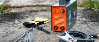
To create a homemade DC welding machine, you will need a high-power electric current source that converts the standard household voltage and ensures a constant value of the electric current for igniting and maintaining the electric arc.
A DC welding machine has a number of advantages: soft arc ignition and the ability to connect thin-walled parts.
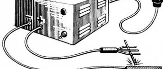
Block diagram of the apparatus for welding work
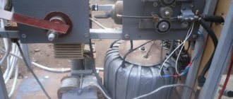
The power supply is installed in a housing made of plastic or sheet metal. The power supply unit of the unit is equipped with all the components necessary for operation: connectors, switches, terminals and regulators. The body of the unit for welding work is equipped with special holders and wheels for transportation.
The main condition when designing a unit used for welding is an understanding of the operating principle of the device and the essence of the welding process itself. In order to construct your own welding machine, you need to understand the principles of ignition and combustion of the electric arc and the basic principles of melting the welding electrode.
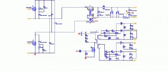
The procedure for connecting the elements of a DC welding machine.
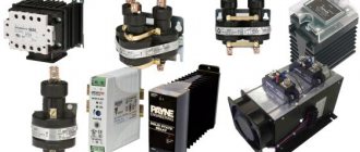
The high power power supply includes components such as:
- rectifier;
- inverters;
- current and voltage transformer;
- regulators that help improve the quality characteristics of the resulting electric arc;
- additional facilities.
The main component of any welding machine is the transformer. Auxiliary devices may have different organization patterns depending on the design of the device.
Features of the welding station
A welding station is usually called a welder's workplace. It includes everything necessary for the full implementation of various types of work. The post and all materials do not always have to be located in a specially prepared room.
If necessary, welding equipment is moved to an open area. Therefore, posts are divided into two types - stationary and mobile (mobile). Welding transformers will be located at the workplace to carry out welding with alternating current, or a rectifier for direct voltage. Welding stations often include:
- Switch.
- Power network.
- Electric holder.
- Welding cables.
- Power supply.
- Exhaust probe.
The post cabin must also have its own specific dimensions: 1.5 m and at least 2 meters in height. Inside it is equipped with a metal table; an exhaust probe must be installed in the upper part. The table has one or more drawers for storing any tool. You should never forget about personal protective equipment; this includes overalls, which must be issued to the welder.
Transformer for welding
A DC welding machine in its design includes a transformer as its main element, which reduces the normal mains voltage from 220 V to 45-80 V.
Diagram of a transformer for welding.
This structural element operates in arc mode with maximum power.
The transformers used in the design must withstand high current values during operation, the rated strength of which is 200 A. The current-voltage indicators of the transformer must fully comply with the special requirements that ensure the operating modes of arc welding. Some homemade transformer welding machines are simple in their design. They do not have additional devices for adjusting current parameters. Adjustment of the technical parameters of such a device is carried out in several ways:
- using a highly specialized regulator;
- by switching the number of coil turns.
The transformer of the welding unit consists of the following structural elements:
- magnetic circuit made of transformer steel plates;
- two windings - primary and secondary, this transformer component has terminals for connecting devices for adjusting operating current parameters.
Transformer winding diagram.
The transformer used in the welding machine does not have control devices that provide current regulation and limitation on the working winding. The primary winding of the welding transformer is equipped with terminals for connecting control circuits and devices that allow you to configure the welding device depending on operating conditions and parameters of the incoming current.
The main part of the transformer is the magnetic circuit. Most often, when constructing homemade welding machines, magnetic cores from a decommissioned engine or an old power transformer are used. Each magnetic circuit design has its own design nuances. The main parameters characterizing the magnetic circuit are the following:
- magnetic core size;
- number of turns of windings on the magnetic core;
- voltage level at the input and output of the device;
- current consumption level;
- the maximum current received at the output of the device.
These basic characteristics determine the suitability of the transformer for use as a device that promotes the formation of an arc, as well as a device that promotes the formation of a quality weld.
Pros and cons of MMA transformers
Such devices are still very popular today because they are low cost and easy to use. Electricity in this device is converted by a power transformer operating at a frequency of 50 Hz. The electric current first flows to the stationary primary winding, which is represented by an insulated wire. After the magnetic flux is formed, the voltage passes to the secondary winding, which has no insulation and moves. A magnetic field arises. Since the windings have different numbers of turns, it becomes possible to obtain the necessary voltage and current indicators: the more turns there are in the secondary winding, the higher the outgoing current. You can increase the welding current in another way - by bringing the coils closer to each other.
The advantages of transformers include:
- Affordable prices;
- Simple design;
- Reliability.
Among the disadvantages, it is worth noting the significant weight of most transformer models, high noise levels, and relatively low efficiency - no more than 80%. In addition, transformers consume a lot of electricity, so it is not recommended to connect them to a stationary power supply.
Possible details when creating a welding machine
Welding rectifier circuit.
When creating a welding machine with your own hands, the stability of the electric arc is achieved by constant potential. The stability of the arc ensures the quality of the resulting seams. Constant potential is achieved by using high-power rectifiers, which are carried out on diodes that can withstand currents of up to 200 A, such as, for example, the B-200.
These diodes are large in size and require mandatory use to organize high-quality heat removal from massive radiators. This circumstance must be taken into account when manufacturing the structure body. The best option when creating a design would be to use a special diode bridge. The diodes can be mounted in parallel, which significantly increases the output current.
When assembling a structure with your own hands, you need to adjust all its components. If the selection is poor or incorrectly calculated, the design can affect the quality of welding.
Sometimes, with the appropriate selection of parts and components, a truly unique device can be obtained, which has a soft and easy ignition of the electric arc, and parts can be welded even with very thin walls, with almost no splashing of liquid metal.
Schematic diagram of a homemade welding unit
You can make a homemade welding machine based on transistor or thyristor control. Thyristors are more reliable. These control design elements are able to withstand a short circuit at the output and are able to recover from this condition quite quickly. These control system components do not require the installation of powerful cooling radiators. This is due to the fact that the structural elements have low heat generation.
Schematic diagram of a homemade welding machine.
A control system created on transistors is capable of leaving the operating state much faster, since transistors burn out much faster when overloads occur and are more capricious in operation. The circuit, created on the basis of thyristors, is simple and highly reliable.
A control unit based on these elements has the following advantages:
- smooth adjustment;
- presence of direct current.
When welding steel 3 mm thick, the current consumption is about 10 A. The welding current is supplied by pressing a special lever on the fork that holds the electrode.
This design makes it possible to increase safety during work and to work with high voltage, which ensures the stability of the arc. If reverse polarity is used in the work, it is possible to carry out welding work with very thin sheet metal.
Why are rectifiers needed?
A home welding machine may not change the frequency of the electric current, but provide a stable arc in a different way. When using a rectifier, the current first enters the transformer, where the current increases and the voltage decreases. Then the voltage is applied to the semiconductor, which is silicon or selenium diodes. The resulting direct current is supplied to the electrodes.
It is difficult to imagine the rating of the best welding devices without rectifier-type devices, because they:
- Guarantees a stable arc;
- Minimize metal splashing during operation;
- Allows you to save consumables;
- Form a neat seam with a fine pattern;
- Excellent for joining alloyed and non-ferrous metals.
Choosing a welding machine-rectifier is not advisable if:
- Are you interested in budget models?
- There is no possibility to transport the device,
- It is not possible to inspect the device before each use for the quality of insulation, cleanliness and reliability of the terminals.
Welding machine design
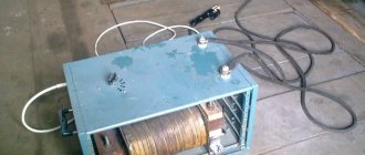
Homemade welding device.
The rectifier of the device is a kind of shelf made of aluminum plates, which is tightened with pins. Each pair of diodes included in the rectifier design is clamped between plates 1 mm thick and measuring 44 x 42 mm.
The transistor, capacitors, thyristors, zener diodes, diodes and resistors are mounted on a fiberglass board.
The design of the welding unit includes the following elements:
- package switch, rated for 16 amperes or more;
- fan;
- diodes designed to operate at currents of 16 amperes or more;
- capacitors designed to operate at voltages of 400 volts or more;
- capacitors designed to operate at voltages of 1000 volts or more;
- thyristors KU221 A, installed on a radiator for cooling;
- KD13A or KD2997A diodes mounted on radiators with thyristors;
- resistors brand C5-16 or more powerful;
- screws, washers necessary for assembling the device;
- aluminum plates.
Read also: Complete disassembly of a black decker screwdriver
To carry out installation work, you will need the following tools:
- soldering iron;
- pliers;
- screwdriver, knife, hacksaw;
- hammer;
- drill.
A welding unit made using these elements can be used for welding work in the household. It easily welds most metal products.
If you need to perform some simple welding work for domestic needs, it is not at all necessary to purchase an expensive factory unit. After all, if you know some subtleties, you can easily assemble a welding machine with your own hands, which will be discussed below.
Welding machines: classification
Any welding machines can be electric or gas. It’s worth saying right away that homemade welding machines should not be gas. Since they include explosive gas cylinders, you should not keep such a unit at home.
Therefore, in the context of self-assembly of structures, we will talk exclusively about electrical options . Such units are also divided into varieties:
- Generator units are equipped with their own current generator. A distinctive feature is its large weight and dimensions. This option is not suitable for home needs, and it will be difficult to assemble it yourself.
- Transformers - such installations, especially the semi-automatic type, are very common among those who make welding equipment themselves. They are powered from a 220 or 380 V network.
- Inverters - such installations are easy to use and ideal for home use; the design is compact and lightweight, but the electronic circuit is quite complex.
- Rectifiers - these devices are easy to assemble and use for their intended purpose. With their help, even a beginner can make high-quality welds.
How to make an inverter-type welding machine
To assemble an inverter at home, you will need a circuit that will allow you to comply with the necessary parameters. It is recommended to take parts from old Soviet devices:
- transistors;
- diodes;
- chokes;
- finished transformers;
- capacitors;
- resistors;
- thyristors.
The following parameters can be selected for the device:
- It must work with electrodes whose diameter does not exceed 5 mm.
- The maximum operating current is 250 A.
- Voltage source - household network at 220 V.
- The welding current adjustment varies from 30 to 220 A.
The tool includes the following components:
We start by winding the transformer and proceed in the following sequence:
- Take a ferrite core.
- Perform the first winding (100 turns using 0.3 mm PEV wire).
- The second winding is 15 turns, wire with a cross-section of 1 mm).
- The third winding is 15 turns of 0.2 mm PEV wire.
- The fourth and fifth - respectively 20 turns of wires with a cross section of 0.35 mm.
- To cool the transformer, use a computer fan.
In order for transistor switches to operate continuously, voltage should be applied to them after the rectifier and capacitors. Assemble the rectifier block according to the diagram on the board, and secure all components of the device in the housing. You can use an old casing from a radio device , or you can make it yourself.
An LED indicator is installed on the front of the case , which shows that the device is connected to the network. Here you can install an additional switch, as well as a protective fuse. It can also be installed on the back wall and even in the case itself.
It all depends on its size and design features. A variable resistance is installed on the front of the housing; it can be used to regulate the operating current . When you have assembled all the electrical circuits, check the device with a special device or tester and you can test it.
The best welding machines for manual MMA arc welding
Having considered the key characteristics, it will be easier for you to choose a device for the upcoming tasks. Next, we present a rating of the best models that have received the largest number of positive customer reviews. Perhaps among them you will find one that suits your needs.
The best MMA welding machines for 140-200 A
Transformers and inverters rated at 140-200 A are household models that are used in the country, in the courtyard of a private house, or in the garage. They are suitable for a small private workshop. They are called household because of their connection to a 220 V network and the ability to weld only thin iron up to 4-5 mm in cross-section. Here is a ranking of the best models in this category.
RESANTA SAI-140
Welding machine from a domestic manufacturer. The current range is 10-140 A. There is a rotary regulator with a drawn scale. Two indicators on the case indicate network connection and overheating. The inverter casing is entirely made of steel, which protects internal parts from shock. The 75V idle makes it easier to ignite the electrode. At maximum PV current, 70% is acceptable. The housing has a degree of protection IP21. The wide shoulder strap makes it easy to transport and work at heights. This is quite possible since the inverter weighs 4.3 kg.
Watch the product video
+ Pros of RESANTA SAI-140
- Full metal body.
- Comfortable shoulder strap.
- There are two additional functions (“Anti-stick” and “Hot start”).
- Easy ignition of the electrode.
- Weighs 4.3 kg.
- You can cook from a gas generator with a power of 3 kW.
— Disadvantages of RESANTA SAI-140
- No display.
- You can cook maxima with an electrode 3 mm in diameter.
- Flimsy mass clamp and holder.
- Short cables included.
Conclusion . This is one of the cheapest inverters for manual MMA welding. Its cost is explained by its simple configuration and maximum welding current of 140 amperes. The unit is notable for its ability to weld at a reduced voltage of 140 V. If your power line is weak, then this is the best option.
PATRIOT Max Welder DC-200
Second place in the ranking is given to an American brand produced in China. The inverter has a current of 10-200 A and an open circuit voltage of 75 V. A wheel and a drawn scale are provided to adjust the welding current. The front panel is equipped with two indicators that indicate connection and overheating. The device can be carried using a wide strap, which is not difficult to do with a weight of 4.5 kg. The holder included in the kit is equipped with multi-position copper plates for clamping the electrode at different angles.
Watch the product video
+ Pros of PATRIOT Max Welder DC-200
- The weight of the unit is 4.5 kg.
- Welding wire with a cross section of 25 mm².
- Compact dimensions 300x120x190 mm.
- Easy ignition of the electrode.
- Three additional functions at once.
- It works very quietly.
— Cons of PATRIOT Max Welder DC-200
- Sold without case.
- Short wires 1.8 m each.
- No screen for visual control of settings.
- The front and back walls of the case are made of plastic.
- Flimsy holder.
- The “crocodile” mass has a small contact area and heats up.
Conclusion. This is one of the best household-class devices in terms of price and performance. It is suitable for manual welding with electrodes up to 5 mm in diameter. Not every model is capable of this. The increased power allows you to use the inverter for welding gate hinges, greenhouse frames, and gazebos. They will also be able to cut a corner using electric welding, which does not require additional tools (grinders, hacksaws).
DIY welding transformer
The assembly of the transformer version will be slightly different from the previous one. This unit operates on alternating current, but for welding with direct current you need to assemble a simple attachment for it.
To work, you will need transformer iron for the core, as well as several tens of meters of thick wire or thick copper busbar. All this can be found at the metal collection point. The core is best made U-shaped, toroidal or round. Many also take the stator from an old electric motor.
The assembly instructions for the U-shaped core look like this:
- Take transformer iron with a cross-section from 30 to 55 cm2. If the figure is higher, the device will be too heavy. And if the cross section is less than 30, the device will not be able to work correctly.
- Take a copper winding wire with a cross-section of about 5 mm 2, equipped with heat-resistant fiberglass or cotton insulation. Insulation is important because during operation the winding can heat up to 100 degrees or more. The winding wire has a square or rectangular cross-section. However, such an option is difficult to find. An ordinary one with a similar cross-section will do, but you will only need to remove the insulation from it, wrap it in fiberglass and thoroughly soak it with electrical varnish, and then dry it. The primary winding has 200 turns.
- The secondary winding will require about 50 turns. There is no need to cut the wire. Connect the primary winding to the network, and on the secondary wires find a place where the voltage is about 60 V. To find such a point, unwind or wind additional turns. The wire can be aluminum, but the cross-section must be 1.7 times larger than for the primary winding.
- Install the finished transformer into the housing.
- To bring out the secondary winding, copper terminals are required. Take a tube with a diameter of 10 mm and a length of about 4 cm. Rivet its end and drill a hole with a diameter of 10 mm, and insert the end of the wire, previously cleared of insulation, into the other end. Next, crimp it with light hammer blows. To strengthen the contact of the wire with the terminal tube, apply notches to it with a core. Screw homemade terminals to the body with nuts and bolts. It is best to use copper parts. When winding the secondary winding, it is advisable to make taps every 5-10 turns, they will allow you to change the voltage on the electrode in steps;
- To make an electrical holder, take a pipe with a diameter of about 20 mm and a length of about 20 cm. At the ends, about 4 cm from the end part, cut out recesses to half the diameter. Insert the electrode into the recess and press it with a spring based on a welded bush of steel wire with a diameter of 5 mm. Attach the same wire that was used for the secondary winding to the second terminal using a nut and screw. Place a rubber tube with a suitable inner diameter onto the holder.
Read also: A mixture of aluminum and iron
It is best to connect the finished device to the network using wires with a cross-section of 1.5 cm2 or more, as well as a switch. The current in the primary winding usually does not exceed 25 A, and in the secondary winding it fluctuates between 6-120 A. When working with electrodes with a diameter of 3 mm, stop every 10-15 to allow the transformer to cool down . If the electrodes are thinner, this is not necessary. More frequent breaks are needed if you are working in cutting mode.
Do-it-yourself mini-welding
To assemble a miniature welding machine yourself, you will only need a few hours and the following materials:
- graphite rod from an old battery;
- side cutters or pliers;
- knife;
- dry rag;
- sandpaper;
- gloves;
- 20 cm of wire with a diameter of 5 mm made of aluminum or copper;
- 6 cm of PEV 0.5 copper wire;
- insulating tape;
- stranded wire;
- any metal clamp;
- a transformer from a microwave power supply with a rectifier, or an old TV or receiver.
First, carefully disassemble the old battery and remove the graphite rod from it. Sharpen the end with sandpaper and wipe with a dry cloth. Clean a piece of thick wire 4-5 cm from the end from the insulation and use pliers or side cutters to bend a loop. Insert a carbon electrode into it.
Remove the secondary winding from the transformer and wind 12-16 turns of thick wire in its place. Now all this is inserted into a suitable housing - and the device is ready.
Its wires are connected to the terminals of the secondary winding, the carbon rod is inserted into the loop and crimped well. Connect the positive terminal to the electrode holder, and the negative terminal to the twist of the working parts. The holder handle can be adapted for an electrode.
You can use a soldering iron handle or something similar. Connect the device to a household network and connect the parts using graphite . A flame should appear, and a spherical weld seam will form at the end of the parts.
For a home workshop, having a welding machine is very important. Such devices have different designs and modifications . Both beginners and experienced craftsmen often prefer not factory-made, but home-made devices that can be modified in their own way.
Welding work at home has long become commonplace. Availability of equipment and consumables, the opportunity to inexpensively attend welding courses, various training manuals for acquiring independent skills. All these factors make it possible to save on the labor costs of a professional welder and increase the efficiency of work.
However, if you carefully study the welding machine market, unpleasant aspects become clear:
- High-quality welders have a high cost; it is more profitable to hire a specialist several times (unless, of course, you do this work constantly).
- Affordable units have a number of disadvantages: low reliability, poor seam quality, dependence on the supply voltage and type of consumables.
Hence the conclusion: if you need high quality equipment at an affordable price, you will have to make a welding machine from available materials with your own hands.
Advantages of semi-automatic welding
Among household welding machines, semi-automatic machines have gained great popularity. Welding can be carried out using self-shielding wire without the use of gas, or with wire in a shielding gas environment. The latter can be used helium, carbon dioxide, argon, which displace air from the place where the weld is formed. Thanks to this, the connection is strong and free of defects. Arc movements during semi-automatic welding are carried out manually, the wire ejection is controlled by special programs. Thanks to this, the semi-automatic machine is easy to use and ideal for beginners. The operating mode of the device depends on the wire feed speed, its type, type of gas and current strength.
A home welding machine operating in semi-automatic mode has the following advantages:
- You can correct the work directly during the welding process.
- High speed of work (up to 18 m/min) and high-quality connections as a result.
- The welding speed is smoothly adjustable.
- Guarantees strong seams when welding thin metal.
- Has many settings and additional modes.
- You can weld either spot or continuous seam. Welding is carried out in all spatial positions.
The disadvantages of a semi-automatic machine include:
- High cost of the device and consumables.
- The connection is not to a household power supply.
- Problems arise when working in an open space: the protective gas is blown away by the wind, and the connection may become unstable.
Before considering options for homemade welders, let’s look at the principle of their operation.
The operation of any unit is based on Ohm's law. At constant power, there is an inverse relationship between current and voltage. For normal operation, a current of 60–150 A is required. Only in this case will the metal in the welding zone melt. Let's imagine a welding machine that operates directly with a voltage of 220 volts. To achieve the required current, a power of 15–30 kW will be required. Firstly, for this it will be necessary to lay a separate power supply line: most inputs into residential premises are limited by technical conditions at the level of 5–10 kW. In addition, such a current will require wiring with a cross-section of at least 30 mm². You will have to cook in compliance with protective measures when working in electrical installations up to 1000 volts: rubber boots, gloves, work area fencing, etc.
Of course, it is impossible to ensure such conditions in reality.
Therefore, any welding machine converts the voltage (downward): at the output we obtain the desired current while maintaining reasonable power.
The optimal voltage value is 60 volts. With a welding current of 100 A, this is a completely acceptable 6 kW of power. How to convert voltage?
Choosing the right model
How to choose a welding machine that, with intensive use, will last for many years without breakdowns? First of all, you need to decide what brand the device will be and what technical characteristics it will have.
Imported devices are most often represented by Chinese-made models - Aurora, Svarog, Foxweld, etc. You should not be afraid for the quality of such a product, since these are fairly well-known brands that control products at all stages of production. Those who prefer European brands can opt for welders from ESAB, Fubag and some models from Elitech. For adherents of Russian technology, models from the Kedr, Resanta or Interskol brands are suitable.
Pay attention to the supply voltage: a household welding machine can be connected to a regular electrical network, but an advanced welder will only work with three-phase voltage. The no-load voltage is also important, which allows you to quickly ignite an electric arc and ensure its uniform combustion. Devices using direct current for welding have HCV up to 90 V, devices for alternating current - up to 80 V.
The power of a welding machine depends on the amount of current it can produce. Devices intended for use at home, on a construction site, in small production, produce a current of 200 - 250 A. A welding inverter for large industrial work produces a current of 250 - 500 A.
The functionality of the device is also indicated by the duration of the operating time - the time period during which the equipment is able to work without shutting down. Please note that European manufacturers calculate this indicator at a temperature of + 40 degrees Celsius, Chinese - at a temperature of +20 degrees Celsius.
The best welding inverter will have a high degree of protection from environmental influences. The most popular models are with degrees of protection from IP21 to IP23, the housing of which cannot accommodate objects with a diameter exceeding 12 mm. The most protected from moisture are devices with an IP23 index: water will not enter their housing even when it enters at an angle of 60 degrees.
There are four main types of welding machines
- Transformer. The device operates on alternating current. The main unit is no different from a conventional power supply: the input is 220 volts, the output is the required 60 volts. Due to the possibility of mechanical movement of the secondary winding along the core, the value of the operating current changes.
Advantages: simplicity and low cost of design, maintainability. Disadvantages: large size and weight, alternating current leads to unstable formation of the weld, highly qualified specialist is required for work. - Rectifier. Essentially, this is the same transformer, only with a diode (thyristor) rectifier in the secondary winding circuit.
After converting the voltage through a transformer (with a traditional mechanical current regulator), the secondary AC voltage is rectified in one of the following ways. In primitive (inexpensive) designs, a diode bridge is used. More advanced circuits operate on a thyristor circuit, with the ability to adjust parameters. Advantages: stable welding parameters, the ability to work with various metals, no highly qualified craftsman required. Disadvantages: higher cost, difficulty in repair and maintenance. Some craftsmen convert a simple transformer welder into DC apparatus. To do this, you just need to assemble a powerful rectifier and connect it to the output of the secondary winding. This will require powerful diodes (assembling a bridge) and radiators to dissipate heat.
A common drawback of the considered schemes is the dependence of the output parameters on the quality of the electrical network. If there are voltage sags (this is normal during welding), the characteristics of the output voltage and current change. As a result, the quality of the weld seam suffers. Therefore, manual adjustment of the current strength (by moving the windings) is mandatory.
Any of the listed devices can be assembled independently. Let's review manufacturing technologies by model:
Types of devices
Typically, when carrying out electric arc welding, a simple welding machine is used - a transformer one. It works on the principle of a conventional transformer, lowering the voltage and increasing the current. This device cooks using alternating current.
However, transformer welding equipment is inconvenient and huge in size. For this reason, problems may arise with its movement. For these purposes, a special device on wheels is required.
If you need a mobile welding machine for electric arc welding, then an inverter is an excellent option. This equipment first converts alternating current from the household network into high-frequency current. And after that it converts it to permanent. In addition, devices of this type are lightweight and compact in size.
Inverter arc welding equipment helps achieve maximum arc stability. This is what has a positive effect on the quality of the seam. In addition, the device allows you to use different modes - with direct and reverse polarity.
Transformers (with or without rectifier)
The heart of a transformer is the core. It is assembled from transformer steel plates, which are quite problematic to make by hand. By hook or by crook, the source material is extracted at factories, construction teams, and scrap metal collection points. The resulting structure (usually in the form of a rectangle) must have a cross-section of no less than 55 cm². This is a rather heavy structure, especially after laying the windings.
During assembly, it is imperative to provide an adjusting screw, with which you can move the secondary winding relative to the stationary primary.
In order not to go into the complexity of calculating the cross-section of wires, we will take typical parameters:
- secondary current 100–150 A;
- open circuit voltage 60–65 volts;
- operating voltage when welding 18–25 volts;
- current on the primary winding is up to 25 A.
Read also: Cold forging pattern drawings
Based on this, the cross-section of the primary wire should be at least 5 mm²; if you do it with a margin, you can take a wire of 6–7 mm². The insulation must be heat-resistant and made from a material that does not support combustion.
The secondary winding is made of wire (or better yet, a copper busbar) with a cross-section of 30 mm². The insulation is rag. Don't let the thickness scare you, the number of turns on the secondary is small.
The number of turns of the primary winding is determined by a coefficient of 0.9–1 turns per volt (for our parameters).
The formula looks like this:
W(number of turns) = U(voltage) / coefficient.
That is, with a network voltage of 200–210 volts, it will be about 230–250 turns.
Accordingly, if the secondary voltage is 60–65 volts, the number of its turns will be 67–70.
From a technical point of view, the transformer is ready. For ease of use, it is recommended to make a small margin on the secondary winding, with several branches (at 65, 70, 80 turns). This will allow you to work confidently in places with low network voltage.
Hiding the unit in the housing or leaving it open is a matter of safety of use. A typical DIY welding transformer looks like this:
The optimal material for the case is 10–15 mm textolite.
Adding a rectifier
A homemade powerful welding transformer from a circuit design point of view is a regular power supply. Accordingly, the rectifier is designed as simply as in a network charger for a mobile phone. Only the element base will look several orders of magnitude more massive.
As a rule, a pair of capacitors are added to a simple diode bridge circuit to dampen rectified current pulses.
You can assemble a rectifier without them, but the smoother the current, the better the quality of the weld. To assemble the bridge itself, powerful diodes of the D161–250(320) type are used. Since a lot of heat is generated on the elements when loaded, it must be dissipated using radiators. The diodes are attached to them using a bolt connection and thermal paste.
Of course, the radiator fins must either be blown by a fan or protrude above the case. Otherwise, instead of cooling, they will heat the transformer.
Mini welding transformer
If you do not need to weld rails or channels from 4–5 mm steel, you can assemble a compact welder for soldering steel wire (making frames for homemade products) or welding thin sheet metal. To do this, you can take a ready-made transformer from a powerful household appliance (the ideal option is a microwave) and rewind the secondary winding. Wire cross-section 15–20 mm², power consumption no more than 2–3 kW.
The calculation of the circuit is carried out in the same way as for more powerful units. When assembling the rectifier, you can use less powerful diodes.
Micro welder
If the scope of application is limited to soldering copper wires (for example, when installing distribution boxes), you can limit yourself to a design the size of a pair of matchboxes.
Performed on transistor KT835 (837). The transformer is manufactured independently. In fact, it is a high-frequency boost converter.
Unlike traditional welders, this circuit uses high voltage, up to 30 kV. Therefore, care should be taken when working.
We wind the transformer on a ferrite rod. Two primary windings: collector (20 turns 1 mm), base (5 turns 0.5 mm). Secondary (boost) winding - 500 turns of 0.15 wire.
We assemble the circuit, solder the resistor circuit according to the circuit (so that the transformer does not overheat at idle), the device is ready. Power supply from 12 to 24 volts, with the help of such a device you can weld wire harnesses, cut thin steel, and join metals up to 1 mm thick.
A thick sewing needle can be used as welding electrodes.
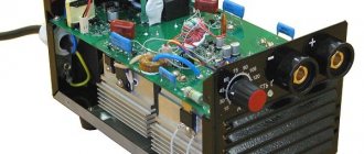
Inverter (pulse power supply for welding)
A homemade inverter welding machine cannot be made simply “on the knee”. This will require a modern element base and experience in repairing and creating electronic devices. However, the scheme is not as scary as it is made out to be. There are a great many similar devices made, and they all work no worse than their factory counterparts. In addition, to create a pulse welding machine with your own hands, it is not necessary to purchase dozens of expensive radio components and ready-made components. Most of them, especially high-frequency elements for the power supply, can be borrowed from old TVs or power supplies from a computer. The cost is close to zero.
The inverter in question has the following characteristics:
- Load current on the electrodes: up to 100 A.
- Power consumption from a 220 volt network is no more than 3.5 kW (current about 15 A).
- Used electrodes up to 2.5 mm.
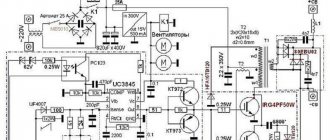
The illustration shows a finished circuit, which has been repeatedly tested by many home craftsmen.
Structurally, the inverter consists of three elements:
- Power supply for the converter and control circuit. Made on an accessible element base, using an optocoupler from an old computer power supply. When making a transformer yourself, the cost is almost zero: the parts are cheap. The values and names of radioelements are shown in the illustration.
- Capacitor charge delay unit (for starting arc). Made on the basis of KT972 transistors (absolutely not a shortage). Of course, transistors are installed on radiators. For switching, an ordinary automotive relay with a current load on the contacts of up to 40 A is sufficient. For manual control, ordinary circuit breakers (packets) of 25 A are installed. Output 300 volts - idle. At load the voltage is 50 volts.
- The current transformer is the most critical component. During assembly, special attention should be paid to the accuracy of the inductors. Some adjustment can be made using a variable resistor (highlighted in red in the diagram). However, if the parameters are not consistent, the required arc power will not be achieved. PWM is implemented on the US3845 chip (one of the few parts that will have to be purchased). Power transistors are the same KT972 (973). Some elements in the diagram are imported, but they can easily be replaced with available domestic ones by searching for analogues on the datasheet website. The high-frequency unit is made from parts of a line transformer from a TV.
Working wires no longer than 2 meters are connected to the output of the welding inverter. The cross-section is at least 10 squares. When working with electrodes up to 2.5 mm, the current drop is minimal, the seam is smooth and even. The arc is continuous, no worse than the factory equivalent.
If there is active cooling (fans from the same computer power supply), the design can be compactly packed into a small case. Considering high-frequency converters, it is better to use metal.
The more complex the homemade welding machine, the greater the savings. It is simple transformers that are more expensive due to the use of expensive copper in the windings or transformer iron. Switching power supplies, especially if you have old parts from standard electrical appliances in stock, are practically free.