If you have the necessary plumbing and electrical installation tools (we will talk about them in detail below), and you have the appropriate professional skills, then you will be able to make a welding transformer with your own hands.
You will, of course, have expenses, but they will be incomparably lower compared to the costs of purchasing a factory-made gadget. But how much pleasure you will get in the process of your favorite homemade work. And the delight at the moment of successful start of electric welding is, in general, incomparable!
In this article we will give you a lot of useful advice on choosing, calculating and manufacturing a welding transformer (hereinafter referred to as ST), which will help you optimize costs and save your budget.
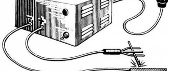
Appearance of a homemade welding transformer. East. https://autokuz.ru/kuzovnoy-remont/kak-sdelat-svarochnyj-apparat-svoimi-rukami.html.
The article will talk about two types of welding transformers. For welding:
- arc;
- contact
Assembly Features
Transformer
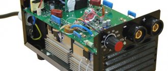
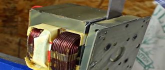
The topic of our article is spot welding from a transformer. We will use a transformer taken from an old microwave. It suits our purposes perfectly. When choosing a transformer, pay attention to its power. To manufacture a point device, you need a transformer with a power of 1 kW or more. A device built on the basis of this transformer will be able to weld metal up to 1 millimeter thick. If you need more power, you can use two transformers. But we'll talk about this later.
Take the transformer and disconnect the magnetic core with the primary winding from it. Often on such transformers the “primary” consists of several turns of thick wire. It is not necessary to remove these listed parts from the frame; it is enough to remove the secondary winding. This can be done using a hacksaw or chisel.
And if the “secondary” is glued, then you will have to use force and literally tear out the winding. Sometimes it is advisable to drill out the “secondary” if other methods do not help. Try not to damage the “primary” and the magnetic circuit itself when removing the secondary winding. If the transformer has shunts, then remove them along with the secondary.
Next you need to wind a new “secondary”. To do this, take a copper wire with a cross-section of 100 mm2 (or 1 cm in diameter). The wires are thick, but this is the cross section that is needed. In total you need to make about three turns. If you manage to make more turns, the device will be more powerful. But we still recommend increasing power using another method. We will talk about this further.
Power increase
As we wrote above, you can use not just one transformer for spot welding, but two. This is necessary in order to obtain more power, and therefore more welding current. Such a combination of two transformers will allow you to assemble a device capable of welding thick metals.
Of course, you can simply make more turns when winding the transformer, but often the core window does not allow this due to the thickness of the wire. In this case, it is better to connect the ends of the secondary windings of two transformers. The connection must be serial. This means that one wire must be pulled through both transformers. The number of turns must be the same.
Be sure to watch the direction of the turns. You should not have antiphase. If you need to make an even more powerful device, then you can connect more transformers. The connection is made using the same method as for two transformers. But take into account your electrical network and think in advance whether it can support such a device. Especially if you are going to cook at the dacha. The use of such powerful devices often leads to scandals with neighbors and broken traffic jams.
Control
The simplicity of a homemade spot welding machine is expressed not only in the internal design, but also in the controls. All you need is an on/off button and a homemade welding gun lever.
With a switch everything is simple. Choose the one you like best. Install it in the circuit with the primary. Do not install it on the secondary under any circumstances, because the current there is too high and the contacts at your button may melt.
With the lever everything is a little more complicated. You must remember that when spot welding, not only local heating of the metal is applied, but also clamping force. The thicker the metal being welded, the greater the force should be. If you weld thin-sheet workpieces, then your own silt will be enough to lower the lever and compress the metal between the electrodes. But if you are planning to assemble a more universal device, then it is better to attach it to a table and make the lever longer and heavier.
If desired, the lever can be modified by adding a screw tie to it. The tie must be installed between the base and the lever itself. Then you won't have to use your own force to compress.
If you have a lever with the simplest design, then the on/off button can be placed directly on it. You lower the lever and at the same time the current turns on. In this case, the second hand will be free, and you will be able to hold the workpiece.
Electrodes
Also, do not forget about the electrodes. Spot welding uses copper electrodes. The thicker the electrode, the better. You can buy electrodes or make them yourself on a machine. But buying is easier and faster. If you are assembling a small, low-power device, you can use a soldering iron tip as an electrode.
Electrodes are consumable materials. They need to be sharpened because they lose their shape. If the original shape is completely lost, the electrode must be discarded and a new one installed.
The electrodes are connected to the transformer using wires. Their length should be as minimal as possible. There should also be few connections, since each connection is always a loss of capacity. It is best if you put special copper tips on the wires, with the help of which the wire will be connected to the electrodes.
Copper lugs should not just be put on the wires, but soldered to them. This is necessary so that there is no resistance at the junction of the tip with the wire and the device can operate stably. In fact, this is a very difficult job and soldering the tip from the wires is quite difficult. But you can buy ready-made tinned tips designed for soldering. Then the task will be easier.
Some craftsmen do not solder the tips, but the electrodes themselves, to make their life easier. But in reality, they only complicate everything, since the electrodes need to be periodically replaced with new ones, which means they need to be soldered off. It's better to just solder the tips once and don't do any more extra work. Moreover, it is easy to clean the tip from traces of oxides.
Read also: Do-it-yourself mushroom cutting drawings
Tools
0 votes
+
Vote for!
—
Vote against!
Today it is difficult to imagine the construction and creation of various metal structures without the use of welding transformers. The high reliability of structural connections and ease of work have allowed the welding machine to firmly take its place in the arsenal of any builder. You can purchase such a transformer at any hardware store. But the factory model may not always meet certain needs and requirements. Therefore, many try to make a transformer for welding on their own. The production of a homemade welding transformer takes place in several stages, starting with calculations and ending with installation.
- Types of homemade transformers for welding
- Transformer for arc welding
- Transformer for spot welding
- Characteristics of welding transformers
- Mains voltage and number of phases
- Rated welding current of the transformer
- Welding current control limits
- Electrode diameter
- Rated operating voltage
- Nominal operating mode
- Power consumption and output
- Open circuit voltage
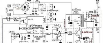
- Welding transformer circuit
- Calculation of a transformer for welding
- Installation of a welding transformer
To understand the entire process of making a transformer for welding with your own hands, you need to understand the principle of its operation, which is to convert a voltage of 220 Volts into a lower voltage of up to 80 Volts. At the same time, the current strength increases from 1.5 Amperes to 160 - 200 Amperes, and in industrial applications up to 1000 Amperes. This dependence for a welding transformer is also called the step-down current-voltage characteristic and is one of the fundamental characteristics of the device. It is on the basis of this dependence that the entire design of the welding transformer is built and all the necessary calculations are performed, and various models of welding machines are created.
Types of homemade transformers for welding
More than two hundred years have passed since the discovery of the phenomenon of the electric arc and the creation of the first welding machine. During all this time, the welding transformer and welding methods were improved. Today you can see several different designs of welding machines, of varying complexity and operating principles. Among them, the most popular ones for making with your own hands are a welding transformer for resistance welding and for arc welding.
Transformer for arc welding
Arc welding transformers are the most widely used among craftsmen. There are several reasons for this popularity. Firstly, the simple and reliable design of the device. Secondly, a wide range of applications. Thirdly, simplicity and mobility. But in addition to the advantages described above, manual arc welding has a number of disadvantages, the main ones being low efficiency and the dependence of the quality of the weld on the skill of the welder.
Manual arc welding is most often widely used for various repair and construction work, manufacturing of metal structures and structural parts, and pipe welding. Using arc welding, it is possible to both cut and weld metal of various thicknesses.
The design of such transformers is quite simple. The device consists of the transformer itself, a current regulator, a holder for electrodes and a ground clamp. It is worth highlighting the central element – the transformer. Its design can be of several types, but the most popular are homemade welding transformers with a toroidal and U-shaped magnetic core. Around the magnetic core there are two windings of copper or aluminum wire - primary and secondary. Depending on the performance characteristics, the thickness of the wire on the windings changes, as well as the number of turns.
Transformer for spot welding
This type of welding is also called contact welding, and contact welding transformers are somewhat different from arc welding machines. The key difference is the welding method. So, if in arc welding melting occurs with the help of an electric arc that occurs between the electrode and the surface being welded, then in contact welding the welding site is spot heated with electricity using two sharpened copper electrodes and high pressure for the connection. As a result, the metal of the workpieces at the point of impact melts and merges.
Spot welding has found wide application in the automotive industry, in construction when creating a frame from reinforcement for reinforced concrete structures, welding thin sheets of aluminum, stainless steel, copper and other metals that require special conditions for welding.
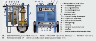
The design of transformers for spot welding also has certain differences. Firstly, this concerns the absence of weldable electrodes. Instead, pointed copper contacts are used, between which the elements to be welded are located. Secondly, the transformers in such devices are less powerful and are made with a U-shaped core. Thirdly, resistance welding machines have a set of capacitors in their design, which is not at all necessary for arc welding.
But regardless of whether you plan to make an arc welding transformer or contact welding transformer, you need to know their operating characteristics. And understand what each of them is responsible for and how one or another characteristic can be changed.
Characteristics of welding transformers
The operation of a welding transformer is determined by its performance characteristics. Knowing and understanding what this or that characteristic is responsible for, you can easily calculate the welding transformer and assemble the device with your own hands.
Mains voltage and number of phases
This characteristic indicates the network voltage from which the welding transformer will be powered. Most often, homemade welding transformers are designed for a voltage of 220 V, but sometimes it can be 380 V. When performing calculations and creating a circuit, this parameter is one of the main ones.
Rated welding current of the transformer
This characteristic is basic for any welding transformer. The possibility of welding and cutting a metal workpiece depends on the value of the rated welding current. In homemade and household welding transformers, the rated current value does not exceed 200 A. But this is more than enough, especially since the higher this figure, the higher the weight of the transformer itself. For example, in industrial welding transformers, the welding current can reach 1000 A, and the weight of such devices will be more than 300 kg.
Welding current control limits
When welding metal of different thicknesses, a certain amount of current is required, otherwise the metal will not melt. For this purpose, a regulator is provided in the design of welding transformers. Most often, adjustment limits are set based on the need to use electrodes of a certain diameter. For homemade arc welding machines, the adjustment limits range from 50 A to 200 A. For contact welding transformers, the adjustment limits range from 800 A to 1000 A or more.
Electrode diameter
To weld metal of different thicknesses using the same arc welding machine, it is necessary to adjust the rated welding current, as well as use electrodes of different diameters. It is necessary to clearly understand that welding with thin electrodes requires a low current strength, and for thicker electrodes, on the contrary, a high current is required. The same applies to the thickness of the metal. The table below provides a summary of the diameters of the electrodes used, depending on the thickness of the metal and the current strength of the transformer.
Important! For resistance welding transformers, the diameter of the electrodes is also important. But in this case, two parameters are used - the diameter of the electrode itself and the diameter of its cone-shaped part.
Rated operating voltage
As we already know, the welding transformer works to reduce the incoming voltage to a lower value. The output voltage is called nominal and does not exceed 80 Volts. For arc welding transformers, the rated voltage range is between 30 – 70 Volts. Moreover, this characteristic is not adjustable and is set initially. Transformers for spot welding, unlike arc welding, have an even lower rated voltage of the order of 1.5 - 2 Volts. Such indicators are quite natural, given the relationship between voltage and current. The higher the current, the lower the voltage.
Nominal operating mode
This performance characteristic is one of the key ones. The nominal operating mode indicates how long you can work continuously and how long you need to let it cool down. For homemade welding transformers, the rated mode is within 30%. That is, out of 10 minutes, 3 can be cooked continuously and left to rest for 7 minutes.
Power consumption and output
In fact, these two indicators have little effect. But knowing both of these indicators, you can calculate the efficiency of the welding transformer. The smaller the difference between power input and output, the better. It should be noted that when performing calculations, the value of power consumption must be known and taken into account.
Open circuit voltage
This indicator is important for arc welding transformers. He is responsible for the appearance of the arc. The higher this indicator, the easier it is to trigger a welding arc. But the no-load voltage is limited by safety regulations and should not exceed 80 Volts.
Welding transformer circuit
When creating a transformer for welding with your own hands, you cannot do without its circuit diagram. In fact, there are no particular difficulties in this, especially since the design of the transformer itself is quite simple. The diagram below shows the simplest arc welding transformer.
Important! Those who have little or no understanding of electrical circuits should first familiarize themselves with GOST 21.614 “Conventional graphic images of electrical equipment and wiring in the original.” And only then proceed to creating a circuit for a welding transformer.
With the development of electrical engineering and technology, the welding transformer circuit has been improved. Today, in homemade welding machines you can see diode bridges and various regulators of the welding current. The diagram of the arc welding transformer below shows how the diode bridge is integrated into it.
Important! The most popular among homemade arc welding transformers is the toroidal one. Such a device has excellent performance characteristics, which are an order of magnitude higher than those of transformers with a U-shaped core. This concerns, first of all, the high efficiency and rated current, which has a beneficial effect on the overall weight of the device.
Unlike those described above, the transformer circuit for spot welding is more complex and may include capacitors, thyristors and diodes. This filling allows you to more finely regulate the current strength, as well as the time of contact welding. An approximate diagram of a transformer for resistance welding can be seen below.
In addition to the above diagrams of welding machines, there are others. Finding them won't be difficult. They are posted both on the Internet and in various magazines and books about electrical engineering. Having acquired the circuit you like best, you can begin calculating and assembling the welding transformer.
Calculation of a transformer for welding
As already described, a transformer consists of a core and two windings. It is these structural elements that are responsible for the main performance characteristics of the welding transformer. Knowing in advance what the rated current, voltage on the primary and secondary windings, as well as other parameters should be, calculations are performed for the windings, core and wire cross-section.
When performing calculations of a transformer for welding, the following data is taken as a basis:
- voltage of the primary winding U1. Essentially, this is the network voltage from which the transformer will operate. Can be 220V or 380V;
- rated voltage of the secondary winding U2. Electricity voltage, which should be after the incoming voltage has been reduced and not exceeding 80 V. Required to initiate the arc;
- rated current of the secondary winding I. This parameter is selected based on what electrodes will be used for welding and what maximum thickness of metal can be welded;
- cross-sectional area of the core Sc. The reliability of the device depends on the area of the core. The optimal cross-sectional area is from 45 to 55 cm2;
- window area So. The area of the core window is selected based on good magnetic dissipation, removal of excess heat and ease of wire winding. Parameters from 80 to 110 cm2 are considered optimal;
- current density in the winding (A/mm2). This is a rather important parameter responsible for electrical losses in the transformer windings. For homemade welding transformers, this figure is 2.5 - 3 A.
As an example of calculations, let's take the following parameters for a welding transformer: mains voltage U1=220 V, secondary winding voltage U2=60 V, rated current 180 A, core cross-sectional area Sc=45 cm2, window area So=100 cm2, current density winding 3 A.
The first thing that needs to be calculated is the power of the transformer itself:
P = 1.5*Sс*So = 1.5*45*100 = 6750 W or 6.75 kW.
Important! In this formula, a coefficient of 1.5 is applicable for transformers with a core of type P, Sh. For toroidal transformers, this coefficient is 1.9, and for cores of type PL, ShL 1.7.
Next, we calculate the number of turns for each winding. To do this, we first calculate the number of turns per 1 V using the formula K = 50/Sс = 50/45 = 1.11 turns for each Volt consumed.
Important! Just as in the first formula, a coefficient of 50 is used for transformers with a core of type P, Sh. For toroidal transformers it will be equal to 35, and for cores of type PL, ShL 40.
Now we calculate the maximum current on the primary winding using the formula: Imax = P/U = 6750/220 = 30.7 A. It remains to calculate the turns based on the data obtained.
To calculate the turns, we use the formula Wx = Ux * K. For the secondary winding it will be W2 = U2*K = 60*1.11 = 67 turns. For the primary calculation, we will perform it a little later, since a different formula is used there. Quite often, especially for toroidal transformers, the current control stages are calculated. This is done to output the wire on a certain turn. The calculation is performed using the following formula: W1st = (220*W2)/Ust.
Where:
Ust – output voltage of the secondary winding.
W2 – turns of the secondary winding.
W1st – turns of the primary winding of a certain stage.
But first it is necessary to calculate the voltage of each stage Ust. To do this, we use the formula U=P/I. For example, we need to make four stages with adjustments of 90 A, 100 A, 130 A and 160 A for our 6750 W transformer. Substituting the data into the formula, we get U1st1=75 V, U1st2=67.5 V, U1st3=52 V, U1st4=42.2 V.
We substitute the obtained values into the form for calculating the turns for the adjustment stages and get W1st1=197 turns, W1st2=219 turns, W1st3=284 turns, W1st4=350 turns. By adding another 5% to the maximum value of the obtained turns for the 4th stage, we get the real number of turns - 385 turns.
Finally, we calculate the cross-section of the wire on the primary and secondary windings. To do this, divide the maximum current for each winding by the current density. As a result, we obtain Sfirst = 11 mm2 and Ssecond = 60 mm2.
Important! Calculation of a resistance welding transformer is performed in a similar way. But there are a number of significant differences. The fact is that the rated current of the secondary winding for such transformers is about 2000 - 5000 A for low-power ones and up to 150,000 A for high-power ones. In addition, for such transformers, adjustment is made up to 8 steps using capacitors and a diode bridge.
Installation of a welding transformer
Having all the calculations and diagram in hand, you can begin assembling the transformer. All work will be not so much complicated as painstaking, since you will have to count the number of turns and not lose count. Despite the fact that the most popular among home-made devices is the toroidal transformer for welding, let’s consider installation using the example of a transformer with a U-shaped core. This type of transformer is somewhat easier to assemble in contrast to the toroidal one and is the second most popular among homemade ones.
We begin work by creating frames for the windings . For this we use textolite plates. This material is used to create stamped circuit boards. We cut out parts for two boxes from the plates. Each box will consist of two top lids with slots for four walls. The area of the internal slots will correspond to the cross-sectional area of the core with a slight increase for the walls of the box. An example of how the parts of the box should look can be seen in the photo.
Having assembled the frames for the windings, we insulate them with heat-resistant insulation . Then we begin to wind the windings.
It is advisable to take wires for windings with heat-resistant glass insulation. This, of course, will be somewhat more expensive compared to conventional wiring, but as a result there will be no headache regarding possible overheating and breakdown in the windings. After we have wound one layer of wiring, we insulate it and only after that we begin to wind the next one. Don't forget to make taps on a certain number of skeins. To complete the creation of the windings, we wind a layer of top insulation. We fix copper bolts at the ends of the bends.
Important! Before installing and securing the bolts at the ends of the wires, we pull the latter through additional holes cut in the top plate of the PCB frame.
Now we proceed to assembling and laminating the magnetic circuit of the welding transformer . It uses hardware designed specifically for this purpose. Metal has certain magnetic induction characteristics, and the wrong brand can ruin everything. The metal core plates can be removed from old transformers or purchased separately. The plates themselves are about 1mm thick, and assembling the entire core will only require patiently connecting all the plates into a single unit. Upon completion, all windings should be checked for errors with a tester.
Upon completion of the transformer assembly, we make a diode bridge and install a current regulator. For the diode bridge we use diodes of type B200 or KBPC5010. Each diode is rated at 50 A, so a welding transformer with a rated current of 180 A will require 4 of these diodes. All diodes are attached to an aluminum radiator and connected in parallel with the inductor to the taps from the windings. All that remains is to assemble the housing and place the welding transformer there.
You may not get a good DIY welding transformer the first time. There are many reasons for this, starting with errors in calculations and ending with a lack of experience in assembling and installing electrical equipment. But everything comes with experience, and by rewinding the transformer windings once or twice, you can get the desired result.
Application nuances
Our homemade device has a very simple design and is unpretentious, but you still need to know some features in order for the device to work properly for many years.
First of all, the device must be turned on or off only when the electrodes are compressed. Otherwise, sparks may appear and the electrodes will simply burn. Also take care of forced cooling of the device. You can use a regular fan for this. If you do not take care of this in advance, you will have to constantly monitor the heating temperature of the device so that it does not overheat. Because of this, you will have to take frequent breaks.
The quality of the resulting weld points will depend not only on how correctly you assembled the machine, but also on how experienced a craftsman you are and how long you compress the workpiece between the electrodes. There are no clear recommendations here; you need to experiment with blanks of different thicknesses and check everything from your own experience.
Features of making your own spot welding for lithium batteries
Everyone knows that lithium batteries are very susceptible to overheating and a resistance spot welding device will help you weld the necessary thin elements to them without any problems. The design feature is that the welding machine is controlled automatically. Let's look at how a device for resistance welding of batteries works with your own hands.
| Illustration | Description of action |
| The device consists of a powerful transformer and a control system. | |
| To automatically turn the pulse on and off, an Arduino controller is used, which controls the triac. In addition, our circuit contains: a power supply for the controller and an input filter. | |
| The required time interval for the pulse is preset, each division is 10 milliseconds. We'll choose 30 milliseconds. | |
| Let's prepare a nickel-cadmium battery for work. | |
| We take the plate and place it under the electrodes. | |
| We press the button and welding occurs. | |
| As a result, we managed to weld “ears” onto the element. |
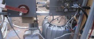
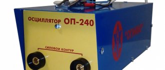
The principle of operation of a spot welding machine from 220V
Look at the picture at the finished unit.
In order for the metal to melt, a very large amount of current must be applied to it. The degree of tension is not important here. 3 Volts or even less is enough. It is not advisable to carry out various experiments with indicators. Homemade welding machines made from a microwave oven transformer have long been tested. They have been tested numerous times and are therefore quite reliable.
The power of the transformer must be selected depending on the thickness of the workpieces. Eg:
- Up to one millimeter - power 1000 Volts.
- Two mm - 2000 volts.
- Three mm - 5000 Volts.
The primary winding must be selected based on the power of the device. Making a transformer yourself is very problematic, so it is advisable to use a ready-made one that fits in a microwave. This unit has its own characteristics:
- The radiating element will require a high voltage - several thousand volts. But the current level will not matter;
- The power on the windings will be the same. If a person wants to increase the number of turns on the secondary winding, then the voltage will increase, but the current will decrease;
- the transforming elements located in the microwave oven have a power of 3000 Volts or slightly less. To perform spot welding, this is quite enough.
The necessary components can be purchased at radio stores. They also use the insides of an old microwave oven. The result is a current power of 1 kA. This value is enough to melt the metal at the contact points. The result is a good connection between several parts. For this purpose, a 3 kW transformer is used.
DIY welding transformer: what we need
The range of tools and equipment for the manufacture and assembly of both types of ST is identical. We will need the following:
- electrical voltage indicator . To control the absence of the latter on electrical contacts, and thereby ensure safety when performing electrical installation work;
- Angle grinder (aka “grinder”, “whip-machine”, etc.) with a set of discs (cutting, grinding, etc.);
- electric drill with a set of metal drills and a core;
- AC tester or voltmeter
- any " scriber ". Used for marking on metal;
- metalwork clamps . For fixing parts when marking “in place”;
- set of power tools . The specific composition of the kit depends on the materials that will be used in the manufacture of the ST. In general, it is like this: a complete electric soldering iron. We will perform soldering using POS-40 solder;
- screwdrivers (various sizes with straight and Phillips slots);
- wrenches: wrenches;
- caps;
- end;
To manufacture a transformer, components and materials are required that differ depending on the type of transformer. In general, the following is required:
- protective casing . Must provide: protection from electric shock;
- exclude the possibility of any objects getting inside the gadget;
How to assemble a transformer - 6 nuances
A magnetron is installed in any microwave oven. He needs significant tension. The transformer has fewer turns in the primary winding, and much more in the secondary. It is on this that the voltage will be 2000 volts. If there is a doubler, the value will increase several times. It is this property that needs to be used.
The transformer must be removed very carefully. To avoid damaging anything, it is not advisable to use various rough tools. First you need to get rid of the body and also remove all fasteners. The transformer is removed from the fixation point. From this device, a magnetic core will be used, as well as a primary winding that has a powerful wire and a small number of turns.
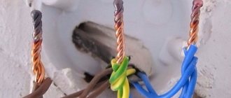
Secondary winding
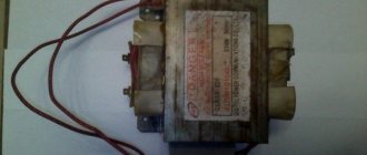
Look at the picture of the secondary winding. There is no need to use it when assembling the weld, so it is advisable to get rid of it. A chisel and hammer are used for this purpose. It is important to carry out all work very carefully so that the required winding does not deteriorate. During work, a person may find a shunt device used in various microwave ovens. You also need to get rid of them.
Magnetic core for welding
Look at the picture of the magnetic circuit attached by welding. If there is a microwire in the microwave oven that is not glued, but welded, then you will have to remove this part using a hacksaw or chisel. The winding will sit firmly in the magnetic circuit, so you need to put in a lot of effort. In this option, you will have to use more crude methods to remove the structure using any available means. But it is worth considering that the operation is carried out very carefully.
After carrying out all the operations described above, we come to the creation of a secondary winding - a solid wire is used, with a diameter of 100 mm square or a little more. This corresponds to one centimeter. A bundle of wires is also used to provide the required diameter.
The winding is created - the transformer will be able to create a current equal to 1 kA. This is exactly what is needed for spot welding.
Read also: Which hole to drill for an 8 mm dowel
If there is a need to make the device more powerful, then a single transformer will not be enough. For this purpose, it is necessary to combine several elements from different microwave ovens. It will take two or three turns.
If the insulation is very thick, it will need to be removed and replaced with a thinner one - preferably fabric. If several transformers are used, then the secondary winding is made according to a common connection diagram. But then you will need to connect the outputs correctly.
How to make your own resistance welding pliers
Manufacturing and selecting pliers for spot welding is the last stage of work on the welding machine. Their choice depends on the nature of the work, the drive system, and the planned size of the parts to be welded.
Sometimes pliers are made from pieces of copper pipes, simply held together with screws.
For the manufacture of clamp electrodes, copper rods or beryllium bronze are used. Some craftsmen use tips from powerful soldering irons as electrodes. One way or another, the diameter of the electrodes should not be less than that of the wires supplying the current. And the pliers themselves must be carefully welded and insulated.
It’s also important to know: 2 nuances about creating a homemade device from two microwave transformers
Look at the picture for a diagram of connecting several devices. If you use several transformers from microwave ovens, then the power of the device will increase. The voltage will increase by 2 times, and the same proportions will apply to the increase in welding current. But with this assembly method, certain losses may also be observed, since the circuit resistance will also increase greatly. The ends of the created winding will need to be connected to the electrodes.
If there are two transformers available, but their voltage is not enough to create a high-quality welding machine, then a series connection of their output windings is used. You should make sure that each element has the same number of turns. This must be done in those cases when it is not possible to wind the required number of turns on the magnetic circuit. When assembling such a device at home, you also need to monitor the direction of the turns.
DIY spot welding from a microwave transformer
Elements of a homemade device
Before making a resistance welding machine, you should first of all worry about a converter, the power of which should be sufficient for the electric pulse to weld the metal.
All these requirements are fully satisfied by the transformer devices included in most models of microwave ovens. To use them, simply remove the built-in secondary winding and replace it with a new one.
When disassembling an old device, you should act extremely carefully, trying not to damage the converter core. All additional elements on it (shunts, in particular) will also need to be removed.
In order to make a transformer for resistance welding (more precisely, its new secondary coil) you will need a thick copper busbar in reliable insulation.
Its thickness should be at least one centimeter, so to obtain the required low-voltage voltage (2 Volts) it will be enough to wind no more than three turns.
To independently assemble a device designed for high power, you will need to use two such transformers connected in series to the power circuit.
When using them, you should proceed from the capabilities of the existing household electrical network and not allow it to operate under significant overload.
The figure shows a circuit diagram for connecting such a complex transformer, consisting of two coils connected in series.
To manufacture a contact block, it will be possible to use the simplest design, which involves the use of standard-shaped welding electrodes.
It is recommended to use copper rods of suitable cross-section and shape as electrodes. Their thickness is selected so that it matches the power of the supply busbars.
In some cases, old soldering iron tips with a power of more than 100 watts can be used for these purposes. The general view of the contact block obtained from these spare parts can be seen in the photo.
How to avoid 4 mistakes when creating electrodes
Look at the picture for the electrodes used on the homemade device. When assembling welding, you need to make the right electrodes. Their diameter must match the wires that are attached to the weld. Copper rods are usually used. But if the power of the equipment is very high, then it is advisable to use a tip from a professional soldering iron.
To connect devices with electrodes, very strong wires are used. If you ignore this rule, then power loss cannot be avoided. Power can also be lost if a large number of different connections are used.
To increase the efficiency of the collecting apparatus, copper tips are used. Then it is possible to avoid power loss in contact areas.
To ensure that soldering occurs without problems, it is advisable to use tinned tips. Since the electrodes are removable, soldering should not be used in the places where they are fixed to the tip. Oxidation forms in these places - the power will decrease. Removable electrodes ensure easy cleaning. It is very comfortable.
The tips will be fixed with the electrodes on the bolts. It is important to ensure that the connection is more reliable. If you do not take care of this, then an increased transition resistance will occur, and therefore the power of the spotter will drop. It is advisable to create a hole of the same diameter for two parts. It is advisable to select the connected elements from copper. The choice of material is not unreasonable - it has low electrical resistance.
Types of resistance welding
Spot welding is one of the most popular types of resistance welding at home. However, there are two more types of welding in this category, which are used most often in factories and in specialized metalworking shops.
- Seam resistance welding.The operating principle of seam resistance welding is no different from spot welding. The tongs we are used to are replaced by special copper rollers. In this case, welding occurs spotwise, but at a certain distance, and the welding seam resembles a path of individual welded sections.
Seam resistance welding is used for welding seams, both on circles and on elongated large sheets. - Butt contact welding. This type of welding is characterized by a larger area of simultaneous welding. An alternating pulse electric current is supplied to the welded products in contact at the joints. Thus, during the application of a pulse, heating occurs over the entire contact area, also called the cross-sectional area. This process is completely mechanized, so it is not suitable for self-assembly at home.
Diagram of a resistance butt welding machine - Capacitor welding. Capacitor welding works on the same principle. It is used in those areas of industry where miniature parts with a thickness of 0.5 to 1.5 mm are fused. This type of welding is used in the field of electronics and instrument making. The advantage is that it leaves virtually no marks and does not burn through the metal.
Homemade capacitor welding machine
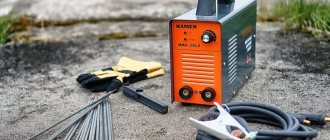
Spot welding machine from a welder
The main difficulty in making a spot welding machine with your own hands is assembling the power source. It must produce short pulses of low voltage and high current, exceeding 1000A. The pulse duration is controlled by a thyristor circuit or manually by a conventional switch on the primary winding. For low-alloy steels, a longer pulse is required; stainless steel is welded with short pulses so that the upper part does not have time to warm up and oxidize, which significantly reduces the anti-corrosion properties.
In the second case, welding with such a machine requires a certain skill - it is very difficult to guess the required pulse duration the first time, especially on different metals. But by trial and error, using scraps of sheet steel or non-ferrous alloys, it is quite possible to achieve welding quality no worse than on industrial machines.
Spot welding, assembled with your own hands from an old welding machine, works quite effectively and is quite capable of solving a number of problems with joining sheet metal with a thickness from a few tenths to 2-3 mm. For thicker sheets, it is difficult to create the required force using homemade pliers or a lever device.
Why is an old transformer chosen? A do-it-yourself spot welding machine involves its complete re-equipment, which, however, only concerns the secondary winding. After the alteration, ordinary MMA welding with such a device becomes impossible, so an old, but still working device is selected; at least the primary winding should be, if not in ideal, then in acceptable condition.
The secondary winding is completely removed and another one is installed in its place, made from an insulated copper strand or busbar. The wire must be insulated very carefully, in several layers of non-flammable insulation. Fabric insulating tape is convenient for these purposes, which alternates with wrapping with ordinary automotive tape, which is used when painting the body.
The cross-section of the secondary winding wire must be at least 1.8 cm 2. If you can find a suitable factory-made insulated cable, it is better to use it. Both cables with a monolithic core and multi-core cables made from copper wires twisted into a bundle give good results. Several turns of cable or bus are applied to the secondary winding in such a way that when 220V is supplied to the primary circuit, a current of 6-8 V appears in the secondary. In this case, the current strength will reach 800-1000 A. This is quite enough for welding individual parts in a home workshop.
Inverter based
Resistance welding from an inverter is one of the alternative options for using an electronic device at home, the choice of which is determined by the special properties of the manufactured industrial samples of this equipment.
The operating principle of a contact point device based on an inverter is based on the same pulsed heating of the metal in the contact zone, followed by its melting and cooling. That is why its assembly in this case is completely identical to the manufacture of a microwave-based welding machine.
If you don’t have an old microwave device on your household, you can use any transformer suitable for these purposes with a power of at least 1 kilowatt.
The only difference between this option and the previously discussed one is the possibility of using non-rectified pulse current in the inverter circuit.
To securely fix the parts to be welded and prevent them from moving apart and forming a gap, the inverter device uses a special compression mechanism.
How to choose electrodes
For resistance spot welding, it is best to use industrial electrodes made in accordance with GOST 14111-69. These can be purchased on Internet sites or in welding equipment stores. When used on homemade equipment, they will last almost forever. But they are quite expensive, especially with press-fit tips made of tungsten or other refractory material.
In most cases, craftsmen make electrodes themselves. Depending on the welding power, copper rods with a diameter of 5 to 15 mm are suitable. On one side, they are inserted into a metal sleeve with clamping bolts, fixed to the cable from the transformer. Like the cable, the electrodes are firmly clamped with bolts.
The second option for attaching the electrode is soldering. This is also a fairly reliable and effective method, ensuring reliable electrical contact, but changing the electrode in this case is more difficult. This does not affect work productivity too much - the electrodes wear out very slowly, especially during amateur welding.
Reliable contact is much more important. If the connection is loose, the wire and electrode will oxidize and overheat, and the current will be less than required. It is also necessary to make all connecting cables as short as possible - the diameter of the electrode and cable must be the same, otherwise there may be surprises in the form of burning insulation or burning of the rods.
It would be useful to recall that the same copper wires are chosen for copper electrodes. Aluminum/copper combinations are unreliable and result in unreliable welding.
The working ends of the electrodes can be pointed (conical), oval or flat. In homemade household devices, it is most convenient to use flat bottom and conical top electrodes. This combination will provide both a high current density at the welding point and reliable support for pressing the parts.
Operating principle of resistance welding machines for spot and seam joints
Spot welding involves clamping the parts to be joined between two copper electrodes. The degree of this clamping must be significant. For this purpose, in the factory, the devices are connected to high-pressure compressors. The electricity supplied to the electrodes through special transformers is characterized by a fairly low voltage, but a high current strength. In the current flow zone, the metal of the parts being connected is melted. In this way, a monolithic point connection is formed.
Devices equipped with a rotation drive produce long suture joints. Instead of point pressure conductive elements, roller electrodes are used here. But the basic principle of operation remains the same. The parts are tightly clamped between two rotating rollers. The seam is formed by melting the pressure points with uniform linear movement of the parts being welded.
The main elements of resistance welding machines are:
- Copper electrodes for spot welding and rollers for seam joints.
- Compression devices or rotation drives.
- Transformers.
- Regulators of the operating current of the secondary winding of the transformer.
- Primary circuit breakers.
- Pneumatic and hydraulic pumping devices or levers for manual pressing.
Copper electrodes can have a relief surface that follows the complex shape of the parts being welded. Some devices are designed for welding elements along their end edges.
Battery spot welding
There is information on the Internet about how to do spot welding with your own hands using a regular 12 V car battery. You can use it to connect small parts that are usually connected by soldering. But in many cases, welding gives better results in terms of strength and is more convenient for joining dissimilar metals.
Do-it-yourself spot welding from a battery is a simple design and can be done in the garage within a few hours, if you have all the parts and tools, of course. Its installation does not require any special devices or complex equipment.
There are three types of battery welding. The first, the simplest, one might say primitive, requires only a battery and two copper wires, the bare ends of which act as electrodes. As a rule, this method is used most often, but only for welding non-ferrous metals. It is precisely this that can rightfully be called a point one.
The other two methods - with carbon electrodes and using an inverter - require a battery of several batteries and additional equipment. They are also used in household and camping conditions, but buying several batteries of the same type to make a welding machine out of them is quite expensive. Any battery that can be removed from the car can be suitable for spot welding.
A simple device for performing welding work consists of two copper wires with a cross-section of at least 1.5 mm 2, fixed in a terminal block. The distance between the stripped ends of the electrodes is 2-3 mm. Of course, as with any homemade design, there can be many options, but as a base it is best to use this type of design. How this mini installation works is shown in the video:
Battery welding is intended for joining small parts made of thin sheet metal, but even then the battery discharges quite intensively. If you removed it from the car, it is advisable to have a charger in the garage to return the batteries to their previous charge.
The examples given are the simplest homemade designs of spot welding machines. If you have your own developments, write to us on the website. We and our readers are very interested in the real developments of amateur designers. We will certainly publish the most interesting schemes.
Recommendations for use
When performing welding work, it is necessary to comply with occupational safety requirements:
- the CT housing must be reliably grounded ;
- The welder must wear special clothing ;
- the head must be protected by a welder’s mask (Chameleon masks equipped with a self-darkening filter are very popular), etc.