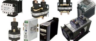
Today, many devices are manufactured with the ability to adjust the current. Thus, the user has the ability to control the power of the device. These devices are capable of operating in networks with alternating and direct current. The design of the regulators is quite different. The main component of the device can be called thyristors.
Also integral elements of regulators are resistors and capacitors. Magnetic amplifiers are used only in high-voltage devices. Smooth adjustment in the device is ensured by a modulator. Most often you can find their rotary modifications. Additionally, the system has filters that help smooth out noise in the circuit. Due to this, the output current is more stable than the input.
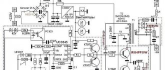
Simple regulator circuit
The current regulator circuit of a conventional type of thyristors assumes the use of diodes. Today they are characterized by increased stability and can last for many years. In turn, triode analogues can boast of their efficiency, however, they have little potential. For good current conductivity, transistors are used of the field type. A wide variety of boards can be used in the system.
In order to make a 15 V current regulator, you can safely choose a model marked KU202. The supply of blocking voltage occurs due to capacitors, which are installed at the beginning of the circuit. Modulators in regulators are usually of the rotary type. They are quite simple in design and allow you to change the current level very smoothly. In order to stabilize the voltage at the end of the circuit, special filters are used. Their high-frequency analogues can only be installed in regulators above 50 V. They cope with electromagnetic interference quite well and do not put a large load on the thyristors.
FakeHeader
Comments 102
Is there a file for the printed circuit board?
How many volts are lost at the output?
I did everything according to your scheme. The current is regulated only between 4-5A! tell me what the problem is!
But no one said a word about the choice of transistor and possibly radiator :). It’s even easier to make a current limiter on lm317, then essentially one TO-220 body and a couple of resistors