Characteristics of a homemade inverter
One of the important questions for welding specialists is how to make a welding inverter with your own hands. The process can be performed using the circuitry of welding inverters.
Before assembling an effective welding inverter, it is necessary to highlight the following technical characteristics of the equipment:
- on one of the transistors, the current that passes through the input should be 32 amperes;
- 250 amperes is an indicator of the current strength that is created when leaving the device;
- the voltage should be up to 220 volts.
In order to create the simplest welding inverter, it is necessary to combine the following elements into one mechanism:
- power block;
- thyristor power supply unit;
- drivers for power switches.
Cooling system
Due to heating, the inverter power units may fail. To avoid this, in addition to radiators with installed heat-prone blocks, fans are also required to prevent overheating.
If there is a high-power fan, you can limit yourself to only that, directing the air directly to the transformer. If you use coolers from an old PC, you will need about 6 of them. How to cool the transformer itself: install three fans at once.
A temperature sensor is installed on the hottest radiator, which turns off the power when it approaches the set temperature.
For normal cooling operation, air intakes with constantly free grilles must be located in the housing.
Materials for its assembly
Drawing of an inverter welding machine.
Before starting to assemble an inverter-type welding machine according to the scheme, the master must prepare the necessary tools and materials that he may need in his work.
First of all:
- various types of screwdrivers;
- a soldering device to connect parts in an electronic circuit;
- knife;
- tool for cutting on a metal surface;
- thread, as a fastener;
- surface with a small thickness of metal;
- parts that form the electrical circuit of an inverter welding machine;
- copper wire and strips to wind the transformer will be required;
- fiberglass;
- mica;
- textolites;
- ordinary thermal paper used in cash registers.
The welding machine circuit is used to assemble equipment at home with an electrical voltage of 220 volts.
But if there is a need, then they use welding machine circuits operating on a three-phase power supply with a voltage of 380 volts. Such equipment has advantages, among which is a high efficiency rate, in contrast to single-phase designs.
Unit power supply
In the power supply of a welding inverter, the most important part is the transformer, which winds with ferrite in Ш7*7 or 8*8.
Inverter power supply.
Using this mechanism, a regular voltage is supplied and is created by 4 windings:
- Primary. One hundred circles of PEV wire with a diameter of 0.3 millimeters.
- The first is secondary. 15 circles of PEV wire with a diameter of 1 millimeter.
- The second is secondary. 15 circles of PEV with a diameter of 0.2 millimeters.
- The third is secondary. 20 circles with a diameter of 0.3 millimeters.
After the primary winding is completed and its sides are insulated using fiberglass, it is also wrapped in shielding wire. Each turn must completely cover the protective layer.
The shield wire winding should be in the same direction as the primary winding. It is worth paying attention to the same diameters of the two types of windings.
The same rule is used for other types: when winding the transformer frame, insulating wires from each other using fiberglass, or using simple masking tape.
To stabilize the voltage in the region of 20-25 volts, which enters the power supply through a relay, a resistor is selected for electronic circuits. The main feature of the mechanism under consideration is the change from alternating current to regular current.
This can be achieved by using a diode formed when performing an “oblique bridge” circuit. It happens that during operation of the device the diode overheats, which is why it is necessary to install it on radiators and often repair the power supply. An alternative to radiators is a cooling part from old equipment.
Installation of a diode bridge involves the use of 2 radiators: the top is connected to one battery through a mica gasket, and the bottom is connected to the second battery through the surface of thermal paste.
The bridge of diodes should be output in the direction where the transistor output is directed. Due to this, direct current turns into alternating current with high frequencies.
The connecting wire of these terminals can reach a maximum length of 15 centimeters. The metal sheet must be placed between the power supply and the inverter part of the device and welded to the “body” of the equipment.
Power block
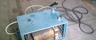
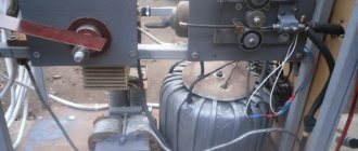
Manufacturing of a welding inverter.
The power unit is the basis of the transformer in the welding inverter. With its help, the voltage indicator at high frequencies decreases, and the power, on the contrary, increases. To create a power block in a transformer, the use of cores is required. To create a small gap, it is recommended to use regular newsprint.
With each applied layer, to ensure thermal insulation, it is necessary to wind cash register tape to achieve good wear resistance. The secondary winding is created on the basis of 3 strip layers of copper, insulated from each other by a fluoroplastic tape.
Most craftsmen wrap a step-down transformer with a thick copper wire, however, this is a mistaken action. With such a transformer, a simple welding inverter will work with high-frequency current, displacing the conductor outside without heating the parts inside.
It is best to form windings using a conductor with a wide surface, in other words, use a wide copper strip.
Instead of a thermal insulating surface layer, experts sometimes replace it with plain paper. It is not as stable as thermal insulation tape or cash register tape. Elevated temperature only affects the darkening of the tape, but its wear resistance remains at the original level.
Inverter unit
The main function of a simple welding inverter is to convert direct current, which is generated using the rectifier of the device, into alternating high-frequency current.
To solve this situation, experts use a power transistor and high frequencies with an opening and closing channel. The mechanism in question in the equipment is responsible for changing direct current into alternating current at high frequencies.
It is recommended to use not one powerful transistor, but a pair with medium power. Thanks to a constructive approach to the problem, the current frequency is stabilized and noise during welding is reduced.
You can make an inverter welding machine with your own hands according to the electrical diagram, which indicates how to connect the capacitors in series.
They are used in the following cases:
- Minimizing surge in the transformer.
- Minimization of losses in the transformer block that appear when the device is disconnected from the network. This occurs due to the fact that the transistor opens at a higher speed than it closes - the current loses its power, which entails overheating of the switches in the transistor block.
Unit cooling system
Electrical circuit of an inverter for welding.
It is worth noting that most power elements in welding equipment tend to become very hot during operation, which can cause it to break.
In order to avoid such situations, it is most effective to install a fan in all units of the device, in addition to the radiator, a cooling mechanism during operation - a kind of cooling system.
You can do it yourself if you have a powerful fan. Often one is used with the air flow directed towards the step-down power transformer.
With a fan that has little power from a computer, for example, you may need up to 6 pieces, of which three devices are installed near the power transformer with the air flow directed in the opposite direction.
To avoid overheating, a homemade welding inverter must work together with a temperature sensor. It is installed on a heating radiator. If the radiator reaches the maximum temperature, it automatically turns off the current supply.
For more efficient functionality of the cooling system of the unit, the housing must be equipped with an air intake with its correct implementation. Air flow passes through its grilles into the internal systems of the device.
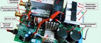
What does an inverter welding circuit look like?
In order to understand what an inverter welding machine is, it is necessary to consider the diagram presented below.
Electrical circuit of inverter welding
All these components must be combined and thereby obtain a welding machine, which will be an indispensable assistant when performing plumbing work. Below is a schematic diagram of inverter welding.
Inverter welding power supply diagram
The board on which the device's power supply is located is mounted separately from the power section. The separator between the power part and the power supply is a metal sheet connected electrically to the unit body.
To control the gates, conductors are used, which must be soldered close to the transistors. These conductors are connected to each other in pairs, and the cross-section of these conductors does not play a special role. The only thing that is important to consider is the length of the conductors, which should not exceed 15 cm.
For a person who is not familiar with the basics of electronics, reading this kind of circuit is problematic, not to mention the purpose of each element. Therefore, if you do not have skills in working with electronics, then it is better to ask a familiar specialist to help you figure it out. For example, below is a diagram of the power part of an inverter welding machine.
Diagram of the power part of inverter welding
DIY inverter assembly
The important question remains: how to make a welding inverter with your own hands? First of all, you need to choose a case with reliable protection or form it yourself using sheet metal, where the thickness should be no less than 4 millimeters.
For the base where the transformer is mounted for inverter welding, getinax sheets with a thickness of no less than 5 millimeters are used. The structure itself will be located on the base thanks to brackets made independently from copper wires with a diameter of 3 millimeters.
To create electronic circuit boards in the electrical circuits of a welding machine, foil-coated textolite is used, the thickness of which reaches 1 millimeter. When installing magnetic cores, which tend to heat up during operation, it is necessary to remember the gaps between them. They are needed so that air can circulate freely.
In order to automatically control the welding inverter, the welder must buy and connect to it a special controller that is responsible for the stability of the current. It also determines whether the supply voltage will be powerful.
For more convenient operation of a homemade unit, a control element is mounted in the outer part. It can act as a toggle switch to activate the device, a knob in a variable resistor, thanks to which it controls the supply of current or a cable clamp and a signal LED.
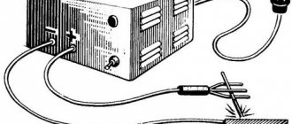
Assembling a welding inverter with your own hands is quite simple if you adhere to all the rules, follow the instructions and strictly follow the prescribed scheme.
Do-it-yourself inverter manufacturing diagram.
AC
Classic welding machines operate on this principle: the voltage from the primary winding of 220 V is reduced to 50 - 60 V on the secondary winding and is supplied to the welding electrode with the workpiece.
Before you start making, select all the necessary elements:
- Magnetic core - stacked cores with a sheet thickness of 0.35 - 0.5 mm are considered more profitable, since they provide the least losses in the iron of the welding machine. It is better to use a ready-made core made of transformer steel, since the tightness of the plates plays a fundamental role in the operation of the magnetic circuit.
- Wire for winding coils - the cross-section of the wires is selected depending on the magnitude of the currents flowing in them.
- Insulating materials - the main requirement for both sheet dielectrics and the native coating of wires is resistance to high temperatures. Otherwise, the insulation of the semi-automatic welding machine or transformer will melt and a short circuit will occur, which will lead to breakdown of the device.
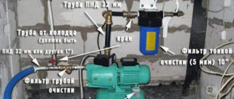
The most profitable option is to assemble the unit from a factory transformer, in which both the magnetic core and the primary winding are suitable for you. But, if a suitable device is not at hand, you will have to make it yourself. You can familiarize yourself with the manufacturing principle, determination of the cross-section and other parameters of a homemade transformer in the corresponding article: https://www.asutpp.ru/transformator-svoimi-rukami.html.
In this example, we will consider the option of making a welding machine from a microwave power supply. It should be noted that transformer welding must have sufficient power; for our purposes, a welding machine with at least 4 - 5 kW is suitable. And since one transformer for a microwave oven has only 1 - 1.2 kW, we will use two transformers to create the device.
To do this you will need to perform the following sequence of actions:
- Take two transformers and check the integrity of the windings powered from a 220V electrical network.
- Saw the magnetic core and remove the high-voltage winding,
Rice. 1: saw the core
Rice.
2: remove the high-voltage winding, leaving only the low-voltage winding, in this case there is no need to wind the primary coil, since you are using the factory one.
- Remove current shunts from the coil circuit on each transformer, this will increase the power of each winding.
Rice. 3: Remove current shunts
- For the secondary coil, take a copper busbar with a cross-section of 10mm2 and wind it on a pre-made frame from any available materials. The main thing is that the shape of the frame follows the dimensions of the core.
Rice. 4: Wind the secondary winding onto the frame
- Make a dielectric gasket for the primary winding; any non-flammable material will do. Its length should be enough for both halves after connecting the magnetic circuit.
Rice. 5: Make a dielectric pad
- Place the power coil in the magnetic circuit. To fix both halves of the core, you can use glue or tighten them together with any dielectric material.
Rice. 6: Place the coil in the magnetic circuit
- Connect the primary terminals to the power cord, and the secondary terminals to the welding cables.
Rice.
7: Connect the power cord and cables Place a holder and an electrode with a diameter of 4 - 5mm on the cable. The diameter of the electrodes is selected depending on the strength of the electric current in the secondary winding of the welding machine; in our example, it is 140 - 200A. With other operating parameters, the characteristics of the electrodes change accordingly.
The secondary winding has 54 turns; to be able to adjust the voltage at the output of the device, make two taps from 40 and 47 turns. This will allow the current in the secondary to be adjusted by reducing or increasing the number of turns. A resistor can perform the same function, but only to a lower value than the nominal value.
Diagnostics of a homemade inverter and its preparation for operation
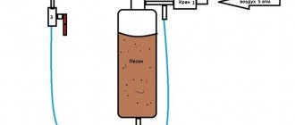
Assembling a homemade welding inverter is not the whole process. The preparatory stage is also considered an important part of the entire work, where it is necessary to check whether all its systems are working correctly and how to configure the necessary parameters.
First of all, equipment diagnostics are carried out, namely, supplying a voltage of 15 volts to the controller and cooling system of the welding machine in order to check their endurance. Thanks to this, the functionality of the mechanisms is checked and the avoidance of overheating during operation of the unit.
When the capacitors in the unit are fully charged, a relay is connected to the electrical network, which is responsible for closing the resistors. With direct supply, without a relay, there is a risk of the device exploding.
When the relay is functioning, voltage is supplied to the device for up to 10 seconds. It is quite important to find out how long the inverter can function during welding. To do this, it is tested for 10 seconds. If the radiator remains at the same temperature, then the time can be set to 20 seconds, etc. up to a full minute.
Units suitable for modernization
The most important parameter of any welding machine is the current-voltage characteristic (CVC), which ensures stable arc burning at different arc lengths. The correct current-voltage characteristic is created by microprocessor control: the small “brain” of the inverter changes the operating mode of the power switches on the fly and instantly adjusts the parameters of the welding current. Unfortunately, it is impossible to reprogram a budget inverter in any way - the control microcircuits in it are analog, and replacement with digital electronics requires extraordinary knowledge of circuit design.
However, the “skills” of the control circuit are quite enough to level out the “crookedness” of a novice welder who has not yet learned to hold the arc stably. It is much more correct to focus on eliminating some “childhood” diseases, the first of which is severe overheating of electronic components, leading to degradation and destruction of power switches.
The second problem is the use of radioelements of questionable reliability. Eliminating this drawback greatly reduces the likelihood of breakdowns after 2–3 years of operation of the device. Finally, even a novice radio engineer will be quite capable of implementing an indication of the actual welding current to be able to work with special brands of electrodes, as well as carry out a number of other minor improvements.
Maintenance of a homemade welding inverter
Drawing of a welding inverter for DIY assembly.
In order for a simple homemade welding inverter to work for a long time, it requires proper care. If the welding equipment breaks down, you need to remove the housing and carefully clean the mechanism with a vacuum cleaner. In parts where it cannot be reached, you can use a brush and a dry cloth.
First of all, for homemade inverters, you need to diagnose all welding equipment - check the voltage, its input and flow. If there is no voltage, it is necessary to monitor the functionality of the power supply.
The problem may also be burnt fuses in the structure. The sensor that measures the temperature, which is not repaired but replaced, is also considered a weak point.
After diagnostics, it is necessary to pay attention to the quality of the connection of the electronic systems of the equipment. Then identify poor-quality fastening by eye or using a special tester.
When these problems are identified, they are eliminated immediately using available parts, so as not to provoke overheating and breakdown of all welding equipment.
Improved heat dissipation
The first drawback that plagues the vast majority of inexpensive inverter devices is a poor heat removal system from power switches and rectifier diodes. It is better to begin improvements in this direction by increasing the intensity of forced airflow. As a rule, case fans are installed in welding machines, powered by 12 V service circuits. In “compact” models, forced air cooling may be completely absent, which is certainly nonsense for electrical equipment of this class.
Read also: Heat-resistant adhesive for aluminum
It is enough to simply increase the air flow by installing several of these fans in series. The problem is that the “original” cooler will most likely have to be removed. To operate effectively in a sequential assembly, fans must have an identical shape and number of blades, as well as rotation speed. Assembling identical coolers into a “stack” is extremely simple; just tighten them with a pair of long bolts along diametrically opposite corner holes. Also, do not worry about the power of the service power supply; as a rule, it is enough to install 3–4 fans.
If there is not enough space inside the inverter housing to install fans, you can install one high on the outside. Its installation is simpler because it does not require connection to internal circuits; power is removed from the power button terminals. The fan, of course, must be installed opposite the ventilation louvers, some of which can be cut out to reduce aerodynamic drag. The optimal direction of air flow is towards the exhaust from the housing.
The second way to improve heat dissipation is to replace standard aluminum radiators with more efficient ones. A new radiator should be selected with the largest number of fins as thin as possible, that is, with the largest area of contact with air. It is optimal to use computer CPU cooling radiators for these purposes. The process of replacing radiators is quite simple, just follow a few simple rules:
- If the standard radiator is isolated from the flanges of the radio elements with mica or rubber gaskets, they must be preserved when replacing.
- To improve thermal contact, you need to use silicone thermal paste.
- If the radiator needs to be trimmed to fit into the case, the cut fins must be carefully processed with a file to remove all burrs, otherwise dust will accumulate on them abundantly.
- The radiator must be pressed tightly against the microcircuits, so you first need to mark and drill mounting holes on it; you may need to cut a thread in the body of the aluminum base.
Additionally, we note that there is no point in changing the piece heatsinks of separate keys; only the heat sinks of integrated circuits or several high-power transistors installed in a row are replaced.
Bottom line
It is a mistake to assume that a device you create yourself will not allow you to effectively perform the necessary work. With a homemade device with an easy assembly circuit, you can weld elements using an electrode with a diameter of up to 5 millimeters and an arc length of up to 10 millimeters.
After the homemade equipment is connected to the circuit, it is necessary to set the automatic mode with a specific current value. The voltage in the wire may be about 100 volts, which indicates some kind of problem.
To fix the problem, you need to find the circuit diagram of the welding inverter, disassemble it and check how correctly it was assembled.
Thanks to such a homemade apparatus, the welder can not only weld homogeneous, dark metal, but also non-ferrous and various alloys. When assembling such a device, in addition to the basics of electronics, you also need to have a free period of time to implement your plan.
The welding process using an inverter is a necessary thing in every man’s home for any domestic and industrial purposes.
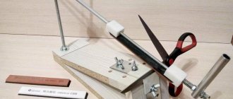
Winding the transformer
The transformer is the power part of the inverter, responsible for lowering the voltage to the operating value and increasing the current to the level of metal melting. To manufacture it, use standard plates of a suitable size or cut out a frame from sheets of metal. The design has two windings: primary and secondary.
Figure 9 — Winding the transformer
The transformer is wound with a strip of copper sheet 4 cm wide and 0.3 mm thick, because the width and small cross-section are important. The physical properties of the material are then optimally used. The wire may not withstand increased heat. The core of a thick wire remains unused at high-frequency currents, which causes overheating of the transformer. Such a transformer will work for a maximum of 5 minutes. Here you only need a conductor of large cross-section and minimal thickness. Its surface transmits current well and does not heat up.
The thermal layer will be replaced by cash register paper. Xerox paper will also work, but it is less durable and may break when winding. Ideally, the insulator should be varnished fabric, which is laid in at least one layer. Good insulation is the key to high voltage. The length of the strip should be enough to cover the perimeter and extend 2–3 cm. To increase electrical safety, PCB plates are laid between the windings.
The secondary winding of the transformer is made of 3 copper strips separated from each other by a fluoroplastic plate. There is another layer of thermal tape on top.
Cash register tape as insulation has one drawback - it darkens when heated. But it does not tear and retains its properties.
It is possible to replace copper sheet with PEV wire. Its advantage is that it is multi-core. This solution is worse than using copper strip, because the bundle of wires has air gaps and they have little contact with each other. The total cross-sectional area is lower and heat transfer slows down. The design of an inverter with PEV consists of 4 windings. The primary consists of 100 turns of PEV wire with a diameter of no more than 0.7 mm. Three secondary ones have 15+15+20 turns, respectively.
Terms of use
Welding equipment requires a responsible attitude:
- Before work, prepare your work area. It's normal to have a lot of free space.
- The inverter does not respond well to temperature changes and weather conditions.
- Avoid dust. It conducts current very well. Industrial plants have compressed air that can be used to blow through equipment.
- Do not overheat the device. Intense electrical processes occurring in circuits lead to great heating. A burnt-out part is a common breakdown problem. On average, continuous operation lasts 5-6 minutes.
- The choice of wires for cables depends on the thickness of the electrode. For household needs, use a 3mm diameter. Welding with this diameter will allow the use of thin and light cables. Their length should not be more than 1.5 m.
- Before work , all wire connections are checked to avoid interruptions in the current supply.
- Attach the plus to the metal, the minus to the holder. Plug in the device and press the start button on the back panel. Set the welding current. Its strength should be sufficient to melt, but not burn through the metal.
- Work is required in special, flame-retardant clothing, gloves and a shield.
Increasing duty cycle
The on-time duration in the context of welding inverters is more reasonably called the load duration. This is the part of the ten-minute interval in which the inverter directly performs work; the remaining time it must idle and cool.
For most inexpensive inverters, the actual PV is 40–45% at 20 °C. Replacing radiators and an intensive airflow device can increase this figure to 50–60%, but this is far from the ceiling. A PN of about 70–75% can be achieved by replacing some radioelements:
- The capacitors around the inverter keys must be replaced with elements of the same capacity and type, but designed for a higher voltage (600–700 V);
- Diodes and resistors from the key harness should be replaced with elements with higher power dissipation.
- Rectifier diodes (valves), as well as MOSFETs or IGBT transistors, can be replaced with similar, but more reliable ones.
It is worth talking about replacing the power switches themselves separately. First, you should rewrite the markings on the element body and find a detailed datasheet for a specific element. According to the passport data, choosing an element to replace is quite simple; the key parameters are the limits of the frequency range, operating voltage, the presence of a built-in diode, type of housing and current limit at 100 °C. It is better to calculate the latter yourself (for the high-voltage side, taking into account losses on the transformer) and purchase radioelements with a maximum current reserve of about 20%. Of the manufacturers of this type of electronics, International Rectifier (IR) or STMicroelectronics are considered the most reliable. Despite the rather high price, it is highly recommended to purchase parts from these brands.