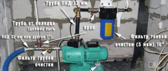
Today, many devices are manufactured with the ability to adjust the current. Thus, the user has the ability to control the power of the device. These devices are capable of operating in networks with alternating and direct current. The design of the regulators is quite different. The main component of the device can be called thyristors.
Also integral elements of regulators are resistors and capacitors. Magnetic amplifiers are used only in high-voltage devices. Smooth adjustment in the device is ensured by a modulator. Most often you can find their rotary modifications. Additionally, the system has filters that help smooth out noise in the circuit. Due to this, the output current is more stable than the input.
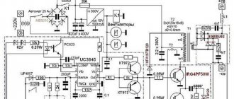
Simple regulator circuit
The current regulator circuit of a conventional type of thyristors assumes the use of diodes. Today they are characterized by increased stability and can last for many years. In turn, triode analogues can boast of their efficiency, however, they have little potential. For good current conductivity, transistors are used of the field type. A wide variety of boards can be used in the system.
In order to make a 15 V current regulator, you can safely choose a model marked KU202. The supply of blocking voltage occurs due to capacitors, which are installed at the beginning of the circuit. Modulators in regulators are usually of the rotary type. They are quite simple in design and allow you to change the current level very smoothly. In order to stabilize the voltage at the end of the circuit, special filters are used. Their high-frequency analogues can only be installed in regulators above 50 V. They cope with electromagnetic interference quite well and do not put a large load on the thyristors.
Charging methods
When charging various computer and home gadgets, direct current is usually directly used. But for car batteries, it is also possible to use alternating current. When charging them, you need to consider the following:
- Using a constant using the selected method ensures the optimal value. As the charge increases, the current will decrease until it drops to zero and the procedure is completed.
- When using alternating current, the battery is charged until the potential difference reaches 14 V. At this point, the current must be halved. After the indicator increases to 15 V, charging is stopped.
In both cases, the initial current must be equal to one tenth of the capacity value, expressed in Ampere * hour.
A block of several batteries Source mysku.ru
DC devices
The DC regulator circuit is characterized by high conductivity. At the same time, heat losses in the device are minimal. To make a constant current regulator, the thyristor requires a diode type. The pulse supply in this case will be high due to the rapid voltage conversion process. The resistors in the circuit must be able to withstand a maximum resistance of 8 ohms. In this case, this will minimize heat losses. Ultimately, the modulator will not overheat quickly.
Modern analogues are designed for approximately a maximum temperature of 40 degrees, and this should be taken into account. Field-effect transistors are capable of passing current in a circuit only in one direction. Taking this into account, they must be located in the device behind the thyristor. As a result, the level of negative resistance will not exceed 8 ohms. High-frequency filters are rarely installed on a DC regulator.
AC Models
The AC regulator differs in that thyristors are used only of the triode type. In turn, transistors are standardly used in the field-field type. Capacitors in the circuit are used only for stabilization. You can find high-frequency filters in devices of this type, but rarely. Problems with high temperatures in models are solved using a pulse converter. It is installed in the system behind the modulator. Low-frequency filters are used in regulators with a power of up to 5 V. Control of the cathode in the device is carried out by suppressing the input voltage.
Stabilization of the current in the network occurs smoothly. In order to cope with high loads, reverse zener diodes are used in some cases. They are connected by transistors using a choke. In this case, the current regulator must be able to withstand a maximum load of 7 A. In this case, the level of maximum resistance in the system must not exceed 9 Ohms. In this case, you can hope for a quick conversion process.
Decluttering and Reusing
A burned out LED should be thrown away. Everything else can be used again.
| Basic information |
| Origin of the concept of power James Watt is known as the inventor of the steam engine. He was born in 1736 in Scotland, where he set up a small workshop at the University of Glasgow and developed an efficient design for using steam to move a piston in a cylinder. Financial problems and the primitive state of metalworking technology delayed the practical implementation of the invention until 1776. Despite the difficulties in obtaining patents (which could only be granted by parliamentary action at the time), Watt and his business partner ended up making a lot of money from their innovations. Although he lived before the founders of electricity, in 1889 (70 years after his death), his name was given to the basic unit of electrical power, which in direct current electrical circuits can be defined as the product of current in amperes and voltage in volts |
| Fundamentals |
| Basics of Watts Until now, I have not said anything about a unit of measurement that everyone is probably familiar with - watts. Watt is a unit for measuring work. Engineers have their own definition of work - they say that work can be done by a person, animal or machine that acts on something to overcome mechanical resistance. An example would be a steam engine pulling a train along a horizontal track (overcoming friction and air resistance), or a person climbing a ladder (overcoming gravity). When electrons make their way through a circuit, they also overcome some resistance and therefore do work, which can be measured in watts. There is a very simple definition: watts = volts × amps Using the usual notation used, three formulas can be given that basically mean the same thing: W = U × I.U = W/I.I = W/U.For watts, the abbreviated international designation “W” is used, in Russian the designation “W”. Together with the abbreviated designations watts, various prefixes can be used, such as “m” to designate “milli” - “mW” (in Russian designation “mW”), however, exactly the same as in the case of using volts or ampere ( Table 2 ). Table 2.
Table 3. The power of incandescent light bulbs is expressed in watts. The power of a stereo system is measured in similar units. Watt was named after James Watt, who invented the steam engine. By the way, watts can be converted to horsepower and vice versa. |
How to make a regulator for a soldering iron?
You can make a current regulator for a soldering iron with your own hands using a triode-type thyristor. Additionally, bipolar transistors and a low-pass filter are required. Capacitors in the device are used in quantities of no more than two units. The decrease in the anode current in this case should occur quickly. To solve the problem with negative polarity, pulse converters are installed.
They are ideal for sinusoidal voltage. The current can be directly controlled using a rotary regulator. However, push-button analogues are also found in our time. To protect the device, the case is heat-resistant. Resonant converters can also be found in models. They differ, in comparison with conventional analogues, in their low cost. On the market they can often be found labeled PP200. The current conductivity in this case will be low, but the control electrode should cope with its responsibilities.
Automation ideas drive progress
One of the branches of electronics is automation and control of electronic and electrical devices.
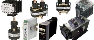
Switching devices – thyristors, divided into types:
- silicon controlled rectifier;
- tetroid thyristor;
- symmetrical (bidirectional) triode thyristor or triac;
- diode thyristor - dinistor;
- symmetrical dinistor.
Various household appliances and electrical tools use a triac power regulator to regulate power.
Charger devices
To make a current regulator for the charger, only triode type thyristors are needed. The locking mechanism in this case will be controlled by the control electrode in the circuit. Field-effect transistors are used quite often in devices. The maximum load for them is 9 A. Low-pass filters are not uniquely suitable for such regulators. This is due to the fact that the amplitude of electromagnetic interference is quite high. This problem can be solved simply by using resonant filters. In this case, they will not interfere with signal conduction. Thermal losses in the regulators should also be insignificant.
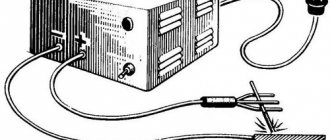
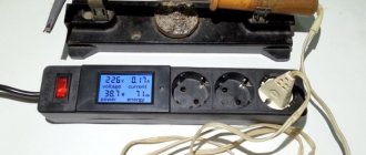
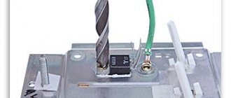
Video description
How to use a light bulb to limit the rectifier current and protect the transformer from short circuit.
When working with car batteries, you can often encounter the use of non-standard chargers. In addition, we must take into account that it can be charged on the go. In all these cases, the current strength can vary within wide limits.
In particular, when recharging while the engine is running, the starting current can be very significant during the first seconds. That is, its strength changes dynamically, so the adjustment must be active, depending on the values of the parameters at this moment.
The principle of battery charging Source ice-people.ru
Regulators for resistive loads
The current regulator circuit for the active load of thyristors assumes the use of a triode type. They are capable of transmitting signals in both directions. The anode current in the circuit is reduced by lowering the limiting frequency of the device. On average, this parameter fluctuates around 5 Hz. The maximum output voltage should be 5 V. For this purpose, resistors are used only of the field type. Additionally, conventional capacitors are used, which on average can withstand a resistance of 9 ohms.
Pulse zener diodes are not uncommon in such regulators. This is due to the fact that the amplitude of electromagnetic oscillations is quite large and needs to be dealt with. Otherwise, the temperature of the transistors quickly increases and they become unusable. To solve the problem with the falling pulse, a wide variety of converters are used. In this case, specialists can also use switches. They are installed in regulators behind field-effect transistors. However, they should not come into contact with the capacitors.
Changing the number of turns
With this method, the arc characteristics are adjusted by changing the transformation ratio. The transformation ratio can be changed by additional taps from the secondary coil. By switching from one tap to another, you can change the voltage in the output circuit of the device, which leads to a change in arc power.
The regulator must withstand high welding current. The disadvantage is the difficulty of finding a switch with such characteristics, a small range of adjustments and discreteness of the transformation ratio.
How to make a phase model of a regulator?
You can make a phase current regulator with your own hands using a thyristor marked KU202. In this case, the supply of blocking voltage will proceed unhindered. Additionally, care should be taken to ensure the presence of capacitors with a maximum resistance of over 8 ohms. The fee for this case can be charged PP12. In this case, the control electrode will provide good conductivity. Pulse converters in regulators of this type are quite rare. This is due to the fact that the average frequency level in the system exceeds 4 Hz.
As a result, a strong voltage is applied to the thyristor, which provokes an increase in negative resistance. To solve this problem, some suggest using push-pull converters. The principle of their operation is based on voltage inversion. It is quite difficult to make a current regulator of this type at home. As a rule, it all comes down to finding the necessary converter.
Pulse regulator device
To make a pulse current regulator, the thyristor will need a triode type. It supplies control voltage at high speed. Problems with reverse conductivity in the device are solved using bipolar transistors. Capacitors in the system are installed only in pairs. A decrease in the anode current in the circuit occurs due to a change in the position of the thyristor.
The locking mechanism in regulators of this type is installed behind the resistors. To stabilize the limiting frequency, a wide variety of filters can be used. Subsequently, the negative resistance in the regulator should not exceed 9 ohms. In this case, this will allow it to withstand a large current load.
Soft start models
In order to design a thyristor current regulator with soft start, you need to take care of the modulator. Rotary analogues are considered to be the most popular today. However, they are quite different from each other. In this case, much depends on the board used in the device.
If we talk about modifications of the KU series, they work on the simplest regulators. They are not particularly reliable and do cause some glitches. The situation is different with regulators for transformers. There, as a rule, digital modifications are used. As a result, the level of signal distortion is significantly reduced.