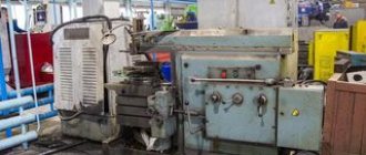
Electrical discharge machining (EDM) involves the removal of layers of material from a workpiece due to the melting and subsequent evaporation of the substance under the influence of electrical pulses arising in the interelectrode gap. A mandatory requirement for a material processed by EDM is its ability to conduct current.
Specialists carry out processing using the electrical erosion method using electrical erosion machines (EDM) of various types. One of the most common EESs are wire-cut ones. In machines of this type, a stretched wire is used as an electrode tool.
Structure and types of equipment for EEE
A typical EDM machine includes:
- several electric motors operating autonomously from each other;
- electrode-tool supply unit;
- bath with working environment;
- table for placing the workpiece being processed;
- control scheme.
The equipment in question is classified according to the following criteria:
- According to technological purpose. It is possible to distinguish universal, specialized and special machines for EEE;
- Based on the principle of arrangement of the main components. It can be made horizontal and inclined, but a vertical layout is more often used;
- By type of table: fixed or coordinate;
- By type of bath – removable or rising;
- According to the degree of accuracy - equipment for work of ordinary precision and precision;
- Based on the principle of excitation and subsequent regulation of electrical discharge parameters.
The size range of types of electrical erosion equipment of domestic production is determined by the requirements of GOST 15954.
Equipment parameters
CNC process control expands the capabilities of metal erosion processing. Deviations of perpendicularity and straightness of movement of the axes are no more than 0.01 microns.
Mechanical accuracy is declared by the manufacturers, and no additional adjustments are required. The machine is completely ready to start the automatic cycle; you just need to load the part model in standard code.
Modern electronics ensure precise movement due to angular and linear sensors, the resolution of which is 1.5 microns. The accuracy of the resulting contours varies from ± 1.5 to ± 5 μm over a length of 300 mm.
Characteristics are selected individually to suit production needs. Based on this, the cost of equipment is formed, focused on a suitable model.
Methods for producing an electrical discharge in the working circuits of machine tools
Dimensional processing can be carried out by spark, pulse and arc discharges. In the first case, a spark discharge of low duty cycle is formed between the cathode and anode, but with precisely specified characteristics of the interelectrode gap. Such machines are compact, distinguished by high accuracy of operation and surface quality after electroerosion, ease of regulation by technological parameters, but at the same time they have low power, and, therefore, productivity. Areas of expedient use of such machines are precise cutting of difficult-to-cut materials (in particular, hard alloys), and production of parts with complex contours. They can also be used to remove broken tools, etc.
Diagram of a wire-cut electrical discharge machine
An increase in the energy of the electric discharge is achieved by introducing a pulse generator into the circuit, which increases the interval between adjacent discharges and at the same time increases the thermal power during a single electrical erosion event. As a result, work productivity increases, but accuracy decreases, and the surface of the machined part may have a fairly extended heat-affected zone, which is not always acceptable. Electric pulse machines are used where more significant metal removal per unit of time is required.
If it is necessary to ensure even higher metal removal (and not only to change the shape of the original workpiece, but also to strengthen it), electric arc machines are used. The productivity of such equipment increases several tens of times, since the arc, unlike other types of electrical discharge, burns continuously. To control the technological parameters of the arc discharge, it is compressed by the transverse flow of the dielectric medium, which is constantly and under high pressure pumped through the arc combustion zone by a pumping unit provided in the machine circuit. Electric arc machines can be used to produce large blanks for rolls, hot hammer dies, etc.
Wire-cut EES: description of the work process
Let us consider in a simplified form the operating principle of wire EPS.
During processing on a wire machine, a process current generator (TCG) supplies a pulse voltage to the wire and the workpiece. Then, when at a specific point in the interelectrode gap the field strength is above the critical level, breakdown occurs and a plasma channel is formed.
Technically, this process resembles a lightning strike, when a high-voltage electrical discharge, moving towards an object on the ground, converts the air into a highly conductive plasma. The impact of discharges on the workpiece forms microscopic holes in it. To ensure that it is the workpiece rather than the wire that is more subject to erosion, the latter is endowed with a negative charge.
The main task of the coolant (water or dielectric compounds) is to remove erosion products from the treatment site. In addition, it cools the wire, which heats up during machine operation.
Electroerosive machine Accutex AL 4005A
A uniform impact on the workpiece can be achieved by supplying high-frequency electrical pulses. As the gap increases, the electrodes can move in the desired direction relative to each other, ensuring continuity of the EEO. In this way, workpieces of any hardness can be cut and processed with high precision. Moreover, the processing area does not always have a cylindrical shape: its inclination can be arbitrarily changed without interrupting the process.
Most often, the workpiece is placed horizontally, and the EI working area is placed vertically. The trajectory along which the center of the wire moves at one end or another of the working area must deviate from the set one by a distance determined by the width of the gap and the radius of the EI. This displacement is called equidistant.
Parts obtained by electrical discharge machining with the movement of a wire electrode along a complex trajectory offset from the vertical.
Factors influencing the processing speed of a workpiece using wire EES
The cutting speed of the workpiece electrode tool depends on the following factors:
- melting temperature of the workpiece material;
- thermal conductivity;
- electrical conductivity;
- intensity of washing the interelectrode gap.
Of course, a number of other, less significant factors are also at play. The processing speed is approximately proportional to the power generated in the gap, but the higher it is, the lower the processing accuracy and the rougher the processed surface. To level out these factors, treatment is usually carried out in several approaches, gradually reducing the power of the GTT and changing the equidistant displacement.
At the last stages of processing, the risk of wire breakage due to its destruction becomes minimal, as does the amount of material removed per pass. Many EDM operators use alternating current or opposite polarity at this stage.
Cutting a stainless steel punch
Requirements for wire-cut EPS
There are a number of requirements for the operation of wire-type EES that the machine must meet:
- safety of use;
- low energy consumption;
- environmental friendliness (no release of harmful substances into the environment);
- ease of use, durability, reliability.
During the cutting process, the electrical erosion specialist must maintain the accuracy of the part dimensions, surface roughness, monitor and adjust the processing speed if necessary. During the work, the specialist can also perform additional functions (for example, carry out precision measurements for correct basing).
Electroerosive machine Accutex HG-40
Application of different types of electrical discharge machines
Among the electric spark type equipment, the MA4720 copying and piercing machine is considered one of the most accurate. It is designed to work with difficult-to-process workpieces of complex configuration, for example, for carbide die equipment, molds, and molds. The productivity of the machine does not exceed 70 mm3/min, but it is possible to achieve an accuracy of 0.03...0.04 mm, with a fairly low roughness of the final surface (not higher than Rz 0.32...0.4 μm in finishing processing modes). The work table is moved by a CNC system. The dimensions of the work table and the permissible range of values of the interelectrode gap between the anode and the cathode do not allow the production of products with overall dimensions of more than 120×180×75 mm on this machine.
An example of an electric pulse machine is the widespread model 4E723, also equipped with a CNC. Higher specific power values make it possible to achieve EDM productivity of up to 1200 m3/min, with a processing error in finishing modes within 0.25...0.1 mm. Higher accuracy is achieved with EDM of shaped surfaces. The machine is also used primarily in tool production, but the surface roughness increases noticeably - up to Ra 2.5 μm, so grinding will be required after processing in most cases. The machine can perform EDM of parts with overall dimensions of 620×380×380 mm, as well as cutting shaped grooves.
These types belong to universal electroerosive machines. An example of specialized equipment is the model 4531 electrical discharge machine, which produces profile cutting of complex contours using a non-profiled electrode. The 4531 machine uses a brass wire that is continuously rewound across the electrode gap, generating a discharge between the cathode and anode. With a relatively low productivity (no more than 16...18 mm3/min for steel; for hard alloy the productivity is even lower), the 4531 machine, in principle, allows for an error of ±0.01 mm, therefore the equipment in question is effective in the production of die cutting dies matrices of particularly complex configurations and templates The maximum dimensions of the cut contour are 100×60 mm.
EES of wire and pierced type: design, differences, features of the EES used
Wire-cut machines are often contrasted with piercing units. The main difference between them is that in wire EPS, productivity is measured by the cutting area per unit of time, and not by the volume of material melted over a certain time period.
It is impossible to judge unequivocally which type of machine provides the best processing quality. The dimensional accuracy of the finished part depends both on the device itself and on the parameters of the workpiece and the properties of the electrode tool.
Cutting process: 1 – workpiece, 2 – spacer, 3 – copier, 4 – table for securing the workpiece.
The EDM process on a wire cutting machine would not be possible without constant updating of the working area of the wire material. During operation, the wire EI is rewound at a speed of 5 to 11.5 m per minute. In this case, it is important that the EI remains under a certain tension and is accurately fixed in the gap of the working area using guides.
In most machines, guides, current supply contacts and tubes supplying jets of coolant are combined into a single system. Current leads are most often made of carbide materials and are located behind the working area, in close proximity to the guides.
When the machine is operating, the coolant must wash not only the erosion gap, but also the entire surface of the wire located between the moving contacts. This is necessary to prevent heating of the wire due to the flow of large pulse voltages through it.
One of the most important operating systems of an EPS is its power supply system. It is responsible for generating and switching voltages of the required value, ensures the correct order of starting and shutting down the EES, diagnoses and monitors the network condition, and ensures the correct operation of the CNC during short-term unexpected power outages.
Principles of optimal choice of technology and machine size for EDM
The initial data are the accuracy of the contour, the dimensions (depth) of the thermally modified zone, as well as the desired removal rate per unit time. For machines working with non-profiled electrodes, it is important to have devices for automatic threading of wire, and for pulse machines - generators that allow the use of bimetallic wire, which increases the productivity of EDM.
To improve the quality of the process and reduce erosive wear of the electrode-tool, it is better to use oil as a working medium (the most common is a mixture of industrial-20 oil with kerosene). In principle, for products with increased tolerances, it is possible to use water.
The technological capabilities of electroerosive machines are significantly expanded by the presence of additional devices (for example, for producing conical surfaces).
To remove metal from 20,000 mm3/min and above, only electric arc machines should be used. The smallest operating error of such equipment is achieved with reverse polarity when using graphite electrodes. At the same time, the relatively high surface roughness - not lower than Rz 0.8...1.6 μm - forces, after EDM with an arc discharge, to provide for finishing grinding of the resulting contour. The pumping pressure of the working medium must be at least 50...60 kPa.
Design
The electroerosive wire cutting machine is equipped with plane-parallel motors. For this purpose, manufacturers create their own neodymium magnets (NdFeB - neodymium-iron-boron). In addition to them, a unique K-SMS control system was also required.
A classic wire-cut EDM machine is capable of processing only electrically conductive workpieces. Metals are burned through an arc to a considerable depth. A smooth surface remains at the cut site, often requiring no additional processing.
An electroerosive wire cutting machine helps to produce complex products: molds, strains, conical and cylindrical surfaces, protrusions and bevels. On sale you can find two-axis assemblies used for simple operations. More complex products are produced using five-axis machines.
Machine feed drives
Electrical erosion destruction is carried out in a working environment, which is supplied to the MEP. Therefore, each EEP machine is equipped with a working fluid supply system, which is shown in Figure 5. Since the working fluid becomes contaminated during the processing process, the layout of the machine also includes a working fluid regeneration system. In EEP machines these two systems are usually combined.
Rice. 5 — RJ supply and regeneration system
- Capacity
- Hydraulic pump
- Pressure gauge
- Filtration system
- Hydraulic distributor
- Valve
- Hydraulic receiver
- Rotameter
- Tap
- Tap
- EI
- Detail
- Working bath
- Drain
Working fluid from the tank >> hydraulic pump. Regulation of the supply of working fluid - with a pressure gauge. Working fluid flow >> filtration system >> hydraulic distributor. When the required pressure is exceeded, the valve opens and part of the working fluid >> hydraulic receiver >> either through valve 10 into the working bath, or through valve 9 through the hollow EI. The workpiece is in the working bath. To regenerate the working fluid >> the working bath through the drain.
Typical representatives
In the process of preparing the abstract, several modern representatives of electroerosive piercing machines equipped with a numerical program control system were disassembled. Such machines as CNC-C90 and ZNC-50 were presented. Their main technical characteristics and features are given below.
Rice. 6 – Electroerosive piercing CNC-C90
| Options | Unit change | CNC-C90 |
| Dimensions of the working fluid bath | mm | 1240 x 700 x 435 |
| Table dimensions | mm | 800 x 450 |
| Move X, Y, Z | mm | 500 x 400 x 350 |
| Distance from the main axis to the plane of the desktop | mm | 650 |
| Movement (quills) along the Z axis | mm | — |
| Max. workpiece weight | kg | 1350 |
| Max. electrode weight | mm | 11 / 200 |
| Max. dielectric capacitance | liter | 600 |
| Max. processing speed | mm3/min | 480 |
| Min. wear rate | % | < 0.1 |
| Max. roughness index of the machined surface | μm | < Ra 0.12 |
| Max. output current | A | 60 |
| Max. input power | kW | 4.06 |
| Machine dimensions (Length x Width x Height) | cm | 205 x 180 x 244 |
| Final weight of the machine | kg | 2,635 |
FEATURES of the piercing machine:
- Program with auxiliary icons for easier work
- Built-in memory, hard disk and support internet or RS232 data transfer program
- Equipped with a high-precision Heidenhain linear encoder (1µm)
- Extended linear stroke for circular machining and moving
- Precision ball screw for precise transmission
- Double filtration system separates carbon residue more efficiently
- Multi-point fire detection system
- Memory for up to 1000 processing parameter settings, 20 spark data per installation
- Vector and Angular EDM Functions
- Ability to edit programs
- GM code and dialog editing function
- 48 processing modes
- Auto memory for 60 working coordinate settings
- Automatic recording of processing time and material consumption
- Available equipment - ATS (4 tools / 6 tools / 20 tools)
Rice. 7 – Electroerosive piercing ZNC-50
| Options | Unit change | ZNC-50 |
| Dimensions of the working fluid bath | mm | 940 x 530 x 350 |
| Table dimensions | mm | 630 x 360 |
| Move X, Y, Z | mm | 350 x 250 x 200 |
| Distance from the main axis to the plane of the desktop | mm | 520 |
| Movement (quills) along the Z axis | mm | 200 |
| Max. workpiece weight | kg | 500 |
| Max. electrode weight | mm | 50 |
| Max. dielectric capacitance | liter | 300 |
| Max. processing speed | mm3/min | 420 |
| Min. wear rate | % | < 0.1 |
| Max. roughness index of the machined surface | μm | < Ra 0.12 |
| Max. output current | A | 50 |
| Max. input power | kW | 3.3 |
| Machine dimensions (Length x Width x Height) | cm | 140 x 138 x 220 |
| Final weight of the machine | kg | 1,375 |
Machine spindle units
Rice. 4 — Design of the piercing head of the EE machine
The spindle of EEP machines is a piercing head; you can see it in Figure 4, which is presented above.
- Hydrostatic guide;
- Spindle;
- Hydraulic cylinder;
- Shaft
- Hydraulic brake
- Gearbox
- Hydropanel
- Frame
- Screed
- Adapter plate
Machine guides
Guides are used to move the moving parts of the machine along the frame, ensuring the correct trajectory of the workpiece or part and for the perception of external forces. All metal-cutting machines use guides: sliding, rolling, combined, fluid friction, aerostatic.
The requirements are: initial manufacturing precision, durability, high rigidity, high damping properties, low friction forces, simplicity of design, the ability to provide adjustment of the gap-tension.
Depending on the location, guides are also divided into horizontal, vertical, and inclined.
Machine support system
The EEP machine bed is made in the form of a box, which gives the structure stability and increased rigidity. The drum carriage, column fastenings, table guides are critical parts of the frame that are subjected to scraping and polishing.
In order to make a frame, you need to use materials that will have high strength and have a low coefficient of thermal expansion. To manufacture the EEP machine bed, a special type of cast iron was used - high-strength.


