Jig boring units have a special place in the world of machine tools, because they perform one of the most difficult tasks - creating high-precision holes with minor deviations in placement relative to each other. Such equipment has a special reading device, which makes it possible to perform high-precision processing of workpieces. The error when drilling holes is up to 1 micrometer. Additionally, coordinate machines are equipped with a device that controls possible deviations, which makes the work process almost like jewelry.
This type of technique is used in the processing of center-to-center holes if it is necessary to achieve the most accurate distances in accordance with the coordinates . During the processing of workpieces, no additional structures are needed to guide the tool.
Contents of delivery
The kit includes a variety of additional tools and special accessories to help you drill and bore holes, cut threads, mill and mark. We are talking about the following elements:
- Ammo.
- Adapter bushings.
- Mandrels for cutters.
- Set of boring bars.
- Universal tool holder.
- Fine feed tool holder.
- Microscope-centrifuge.
- Spring core.
- Installation center.
- Cutters, drills, reamers, taps.
Design
The design of most modern CNC coordinate machines provides for servicing metal workpieces in 3 directions.
A specialized coordinate machine moves the cutter in the longitudinal (X) and transverse (Y) directions horizontally. Vertical movement (Z) is also provided. If the design provides for a special rotating device (processing cylindrical workpieces), horizontal movement can be replaced by rotating the steel raw material along the longitudinal axis. But in any case, the direction of movement of the cutter can only be determined by three independent coordinates.
The technical capabilities of the machine are optimal to move the cutters of the unit along fairly complex routes, simultaneously achieving simultaneous processing of various surfaces without changing the position of the workpiece.
In more advanced equipment, it was possible to modernize the coordinate system of a CNC machine, expanding their number to five. With a kind of “five-axis machining”, processing is carried out around 2 additional axes (the inclination of the tool changes). Setting up the equipment in this case is quite simple - to do this, just load the drawings into the internal memory, after which the CNC of the machine will independently determine the direction in which the movement is carried out. During operation of a CNC lathe, the angle of the tools changes due to the movement of the platform or the tilt of the spindles.
Equipment classification
Boring units have some design features. Depending on the type of work performed, equipment can be specialized or universal.
The main feature of units of this kind is the spindle (can be located in both horizontal and vertical positions), with the help of which the axial feed is driven. Since the equipment is adapted to perform different tasks , the workpiece often goes through a full processing cycle. It is important that the product does not need to be moved between several machines.
Therefore, boring machines are in particular demand in the mechanical engineering industry, where there is an urgent need for constant complex machining of parts. The main characteristic that influences the level of performance is the spindle cross-section. The working tool is fixed in it.
Application area
Jig boring machines for wood and metal are not significantly different from each other, the only difference is what load can be withstood and what cutting tools are installed in the spindle. Of course, on models designed for wood, metal workpieces should not be processed.
A jig turning and boring machine was created to produce center-to-center holes located relative to each other at a certain distance. The device operates without installing special measuring devices that are designed to guide the tool.
It should be taken into account that the operating principle of the jig boring machine involves performing the following operations:
- Obtaining blind and through holes.
- Performing a finishing pass on the surface with a cutter.
- Borings and reamers.
- Marking work and processing of end surfaces.
- Control of specified sizes.
The layout of a jig boring machine determines that most of the workpieces are represented by body parts. In addition, work is being done to create holes in the conductors, in which they must be located with high accuracy relative to each other.
Boring and other operations on a jig boring machine can be carried out as part of the production of medium and large batches of parts.
Components of the machine and an example of machined holes
The installed tools of the jig boring machine also allow marking of parts, mainly center-to-center distances. Design features allow you to create holes that are located at an angle or in mutually perpendicular planes. The spindle of the jig boring machine allows you to create holes that are located on the end sides.
Considering the types and models of jig boring machines, it should be noted that the equipment can be equipped with an optical reading device, as well as a CNC system for monitoring the position of the workpiece and cutting tool. At the same time, manufacturers of jig boring machines indicate that such equipment is a combination of a measuring and metalworking machine. That is why, in some cases, the workpiece is based on the machine in question, but the processing is performed with other equipment.
If the main components of jig boring machines are in good technical condition, then the processing accuracy is 0.004 millimeters. Metalworking equipment of a conventional turning group cannot produce parts with such precise dimensions. Considering GOST and accuracy standards for jig boring machines, it should also be noted that some are equipped with a digital display device, which allows you to control dimensions with an accuracy of up to thousandths of a millimeter.
Types of units
Today there are the following types of these machines:
- Turning and boring.
- Diamond boring.
- Coordinate boring.
- Horizontal boring.
Jig boring units are recognized as the most universal and multifunctional, which allows them to be used for almost all known operations related to hole processing. Such units can carry out marking procedures that require high precision, because they are equipped with electronic, mechanical, inductive and optical counting devices, which guarantee impeccable measurements of the movements of moving units.
The second significant advantage is the universal rotary work table, thanks to which you can work with inclined holes.
Spindle rotation is the main (working) movement, and vertical movement is the feed movement. The composition includes one or two racks.
Horizontal boring machines
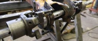
The main distinctive feature of a horizontal boring machine (Fig. 1) is the horizontal arrangement of the spindle. This type of machine is somewhat reminiscent of a conventional screw-cutting lathe. But there are several key differences in a horizontal boring machine. Firstly, the tailstock is missing. Instead of the tailstock, a movable rest is installed. Secondly, the faceplate with which the spindle is equipped has the ability to shift the cutter relative to the axis of rotation, which is not typical for a lathe. Thirdly, there is a table on which the part can be fixed.
Figure 1. Horizontal boring machine
Figure 1. Horizontal boring machine
Let's look at the main components and elements that make up a standard horizontal boring machine.
- Rear pillar. It is designed to attach a movable rest to it. Can be moved on the bed guides. Has a lever to lock the position.
- Lunette. This device is designed to hold the tail part of the workpiece if its length does not allow for reliable fastening to the table. Serves as an additional attachment point. The lunette can move in a vertical plane. Movement in the horizontal plane is carried out through the movement of the rear pillar.
- Front pillar. The main support on which the working part of the machine is mounted is the spindle head. On the front pillar there are vertical guides along which the headstock moves.
- Caliper. This element of a horizontal boring machine serves to feed the cutter to the surface of the workpiece. The support has the ability to move longitudinally in a horizontal plane along the axis of rotation.
- Faceplate (Fig. 2). Unlike the standard faceplate of lathe group machines, it is used to secure the boring cutter in it. It has the ability to shift the cutter relative to the axis of rotation. This allows one tool to perform various boring operations.
- Spindle. Transmits rotational motion from the gearbox to the faceplate.
- Grandma. The working moving part of a horizontal boring machine. Inside the headstock there is an electric motor, gearbox and guides for axial movement of the caliper.
- Remote Control. Includes buttons for changing operating speed, reverse, automatic feed settings and emergency stop.
- Table. Serves for arranging and securing massive parts of small dimensions on it.
- Sled. Used to move the table.
- Bed. It is the base of the machine. On the bed there are two racks and a table. Sometimes the bed has the ability to adjust the installation level of the machine.
Figure 2. Boring machine faceplate.
Figure 2. Boring machine faceplate.
Today, horizontal boring machines that are equipped with a numerical control module are becoming increasingly common.
Workpiece processing
To process the parts you will need special equipment. In most cases, boring heads are used that are mounted in different devices. The heads have an all-metal shank holder; there is a groove on it that moves the slider cutter.
A device is also often used that allows for efficient and quick boring of molds (their dies). The workpiece is placed on the table and secured on both sides with bolts and clamps. The die cavity is processed using a square adjusting head. It is complemented by a regulator ring with a scale and a groove at the bottom. A slider with a cutter on a holder moves along it. Microscrews allow you to adjust the head. It is worth noting that heads are not used in all mechanisms of this type.
Boring equipment has a number of important advantages:
- Simplicity and versatility of technological equipment.
- Increased productivity.
- Reduced production cycle time.
- Rapid preparation of equipment for reorientation to the production of new parts.
Homemade dividing head for a lathe
» Machine » Boring head for milling machine
Boring work, the main purpose of which is to give existing holes the required parameters, can be performed using boring, milling and turning machines. Such work (for example, primary processing of a previously created hole or shifting its position relative to the axis) is performed only after the final completion of drilling (or reaming).
Boring work performed on a milling machine requires special tools.
So, they can be either multi-blade (multi-cutting) or milling cutters, which are constantly rotating bodies during operation, covered with both wear-resistant and durable teeth.
Milling cutters are one of the most important tools that allow processing of metal surfaces and are very diverse.
In fact, a boring head is a piece of special equipment, the main purpose of which is to hold the teeth described above (or cutters, depending on the choice of the main work tool) when using them to perform drilling, boring or other operations (milling).
Part design and operating principle
In general, the boring head allows you to place either one or several cutting elements at once, however, it is recommended to resort to the optimal design with two radially spaced teeth, since this:
- Helps balance the radial component of the cutting force, which has a positive effect on accuracy;
- Significantly reduces the flow of vibration coming from the tool;
- In principle, it has a positive effect on the dynamics of the boring process.
At the same time, increasing the teeth will not have a positive effect on the work, since this entails a complication of the entire structure, plus, it makes it impossible for the operator at the machine to work at high speeds (fraught with the appearance of defects).
The boring head is fastened in the machine spindle (on the main executive body of the milling machine, that is, essentially, a rotating shaft that transmits force from the machine engine), while the part body is firmly fixed using a nut (or a group of nuts, or using micrometric screws).
The main components of the design of such equipment are the following parts:
- The hub is the central part of the equipment with a small hole that is necessary for mounting on the torque element. The mounting location for this part is the shank, described below, fastening is carried out through four screws, two of which additionally connect the quill;
- A quill that secures the cutting element;
- A slider, which is a moving part inside the quill along two guides using a lead screw. With its help, you can adjust the position of the cutting component relative to the center of the existing hole;
- Tapered shank that precisely fits the front spindle bore. Through this part, rotation is transmitted to the tool.
The process of working with the boring head is as follows:
- The shank is inserted into the spindle (into the cone-shaped hole), after which it is tightened with a screw to ensure tightness;
- After this, the part must be firmly installed in a vice or some other similar equipment;
- If it is necessary to bore a hole of less than 40 mm, then the position of the cutting component is adjusted only using a slider;
- In the case of boring a hole with a larger diameter (up to 85 mm), you should first repeat what was described in the paragraph above, after which the slider should be moved to its initial position, loosen the fastening screws and move the quill into the hub until it stops.
Below is a video of preparing the boring head for work and its direct use.
Boring head selection
The main differences between boring heads sold today are the difference in diameters and boring ranges of the surface being machined. When choosing such a special equipment must be based on:
- Slider movement range;
- Permissible speed frequency
- Feed speed (both manual and automatic).
Currently, several manufacturing companies are popular and offer a fairly wide range of products.
Boring heads are especially popular, since these models are both easy to use and allow you to carry out quite complex operations (for example, working out several grooves at once, differing in parameters).
You should also pay attention to products that offer tools with similar parameters; Moreover, some models are suitable even for beginners in turning (for example, the CoroBore 820, which is one of the easiest tools to learn, is capable of working in 4 modes and can be configured to work both in the mode of using several blades simultaneously and with only one).
The Spanish one has also proven itself well in the market, which is mainly focused on middle- and budget-class models and offers perhaps the largest number of different models of boring heads in these market segments.
Conclusion
Since boring heads are currently used not only on milling machines, but also on different types of boring machines (horizontal and coordinate), drilling machines, the variety of their types has reached its maximum today, which is partly explained by the need to perform multi-stage tasks. However, the structural device discussed in this article remains the same, as does the operating principle.
The quality of work on the existing surface directly depends on the choice of the type of boring head, therefore the acquisition of this element should be approached as responsibly as possible, so that in the future it will be possible to carry out multi-stage processing of the part.
www.m-deer.ru
Dividing and boring head for milling machine
The dividing milling head is an additional equipment that expands the capabilities of the milling machine in metal work.
First of all, the milling head is used for the production of various tools - taps, countersinks, reamers, cutters, etc. It is also used when working with profile machine parts - sprockets, gears.
Universal dividing head
The use of such a device allows you to cut grooves and splines on individual surfaces, process the ends of parts, form edges on nuts and bolt heads, and many other technological operations.
Multi-Axis Capabilities
A jig drilling machine allows you to produce complex parts:
- Lugs, holes of non-standard shape.
- Shaped surfaces, cabinet products.
- Gears, gears, impellers, rotors.
- Stiffening ribs can be worked out without difficulty.
- Holes in any projection at various angles, grooves, threads.
- All complex parts requiring curved processing.
- In one cycle, the entire surface of the workpiece can be processed.
Recently, vacuum tables have been widely used to hold the workpiece by suctioning air. Classic fasteners are no longer used, which reduces the time for removing and installing a new workpiece.
Scope of application of coordinate punching
Coordinate punching is used in many industries. The purpose of processing metal of this type is to create finished products, or to produce parts and components for the needs of related production. Punching work is used in the following cases:
- Furniture production - for the manufacture of bases for the backs and seats of chairs, beds, benches, shelves and cabinets.
- For the production of load-bearing parts for office, archive, library, warehouse and industrial shelving.
- In the manufacture of decorative screens and grilles for masking equipment, ventilation, or for safety purposes.
- Individual production of interior parts - decorative partitions, in accordance with design solutions.
- In the production of household items - lampshades for lighting fixtures in the Art Nouveau and high-tech styles, dishes, mortise lock linings and other elements.
- In the manufacture of scaffolding and scaffolding for the needs of construction and installation production.
- For the production of individual body elements of machine tools, conveyor lines, and technological equipment.
Coordinate punching is used in almost all industries - in the automotive industry, aircraft manufacturing, space industry, in the production of advertising structures, sports equipment and other types of products. Many companies offering metal processing services, in addition to mass production, carry out individual orders subject to technical specifications from the client.
Metal coordinate punching technology
All coordinate punching machines, the operating principle of which is based on the method of cold metal stamping, operate in accordance with the following technological algorithm:
- The design of the punch is carried out in such a way that the pressure during impact occurs along the contour of the hole being cut out.
- The matrix, located on the reverse side of the workpiece, creates a response force when lowering the punch.
- The matrix configuration repeats the geometry of the punch, differing slightly in dimensions.
- When pressure is applied, a couple of forces arise from the pressure of the punch and the support reaction of the matrix, which causes a bending moment with a minimum shoulder.
- At the point of minimum bending moment, a maximum transverse force is formed, accompanied by an increase in shear force.
- According to the rules of strength of strength, if the external load exceeds the tensile strength of the material, its structure is destroyed.
- When the shear force exceeds the tensile strength of the steel, a disruption of the crystal lattice occurs. The tensile strength depends on the hardness, chemical composition and method of strengthening the metal. As a result of this action, a hole of the desired shape is cut out.
The amount of pressure per unit area depends both on the force specified by the machine engine and the quality of processing of the edges of the punch and matrix. Thus, to increase the accuracy of punching without deforming the sheet, you should use only high-quality tools with sharpened edges. In general, the operating principle of a coordinate punching machine does not differ from the functioning of ordinary office scissors.
How are movements calculated?
Modern equipment uses two options for determining the position of movements - absolute and relative. The choice in favor of an absolute or relative CNC system is determined based on a number of factors. For example, exactly how dimensional chains are compiled in the drawings. It is common for certain machine control systems to choose between two options - in increments (relative method), or from a specific size base (absolute method).
Regardless of the number of points, a basic dimensional point must be present in the project. In CNC systems, it is convenient to use the base point as a zero point. But in the coordinate systems of CNC machines, you should always use absolute coordinates. Let's look at each system in more detail.
In a system using an absolute reference method, the CNC machine carries out milling operations starting from point P0, moving in a straight line, up to point P1. Using the relative system, lathes, compared to the previously considered option, move according to a different principle.