Because The topic about the compressor has grown to 3 entries; I decided to create an entry covering all aspects of assembling a homemade compressor based on the ZIL-130 head. From idea to implementation. This entry will be updated periodically. Collecting/buying ready-made items is a private matter for everyone. I found a similar compressor in terms of performance and displacement from 15 thousand. Direct drive (small resource). Having thought about it, I started assembling my own.
1) Receiver
(compressed air storage), the larger the better (for direct drive, a large receiver -> rapid wear of the piston) for tire inflation and rare element-by-piece painting, 50 -100 liters is quite enough.
A larger receiver will allow you to get a more stable result. 2) Motor
(electric) to drive the compressor head (recommended with a margin of 20-40%, in order to avoid possible problems of non-starting under load).
(as a rule, motors are asynchronous with capacitors) 3) Protective grille
(so that your hands don’t get wrapped around the belt) 4)
Drive belt
(usually V-shaped, in case of hellish overload it will slip and will not kill the motor) 5)
Check valve
(necessary for starting the compressor under load, principle of operation: do not let it in from the receiver) 6)
Air supply tube
to the receiver (usually copper or aluminum).
7) Compressor head
(usually placed under air cooling, in our case water/antifreeze cooling, for long-term operation it is desirable), the performance of the system as a whole depends on it.
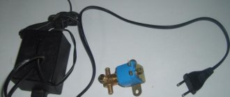
The pressure switch
is the heart of the compressor; in this box there is a pressure switch, usually adjusted to: 8 atmospheres, turn off the engine, reducing the pressure to 4-6 atmospheres starts the engine, and so on in a circle.
This unit also contains a pressure regulator with two pressure gauges - its task is to set the pressure required by the user for a specific tool, for example, a spray gun. Now about pressure gauges, as a rule there are two of them, one shows the pressure in the receiver, the second displays the air flow to the instrument. The output regulator has connecting fittings: either rapid or bypass. There is also a herringbone option). This unit has a small but extremely important part - a pressure relief valve (in common parlance, a fart). It is necessary in case of failure of the pressure switch. 9) Drain tap
- the function of freeing the receiver from condensation (and there will be condensation in any case).
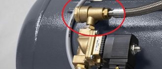
Now let's look at the following non-obvious thing: why is such a long line from the head to the receiver made? Necessary for easier starting of the compressor. The principle of operation of this unit is simple - air from the compressor head passes through the main line through a check valve into the receiver. The compressor has turned off - the check valve has locked the air in the receiver, the air is standing in the tube. The compressor valves are not so tight and gradually bleed air, thereby the pressure in the tube drops. The motor needs a few moments to enter operating mode, and these few moments are provided by the tube and check valve.
Secondly, to reduce condensation at the outlet of the compressor, it is recommended to introduce air further from the outlet.
So, having understood the design of the compressor, and having understood some aspects, it was decided to sculpt a design that is not difficult to repeat.
1) Receiver
- a household propane cylinder 40-50 liters. (Before welding, degass, I am not responsible for your rash actions.) The following are welded into the body of the receiver: a piece of water pipe for a 1/2-inch back pressure valve, a piece of water pipe for a condensate drain tap, M12 nut for the emergency pressure valve (previously it was a valve for a 1/4 thread, I cut it with a die for M12). The air exits through the neck of the cylinder - a 3/4 inch bend, screwed into the cylinder (the cylinder has a 3/4 k thread (conical), screwed in without problems.
To ensure the correct operation of compressor equipment, various technical devices are used, among which is a check valve for the compressor. Without this unit it is almost impossible to imagine the operation of equipment designed for air compression.
Types and principles of operation of valve mechanisms
Currently, the most common types of compressors are screw and piston units. At the same time, screw compressors, for example, those produced by the Belarusian plant REMEZA, are widely used in various industries, and piston compressors are used in everyday life. The latter can be found both in garages of car enthusiasts (compressors such as SO-7B, Forte VFL-50, etc.) and in life support systems for fish in aquariums (Resun compressors, etc.), as well as in household pneumatic tools.
Piston compressors are characterized by a simple design and a relatively small number of parts and components. There are many different designs of such compressor units, equipped with special plate valves that regulate the process of suction and injection of air during operation . Depending on the purpose of compressor units (their performance, power and operating pressure), three types of valve mechanisms can be found:
- disk - their plates can be made of both metal and high-quality polymers, including reinforced ones;
- ring - parts for them are made of cast iron, steel or non-ferrous metals (the choice of material is determined by the type of compressor);
- disc valves - plates for this type of valve are made of polymer materials and are used in compressors operating with contaminated media.
Inlet and exhaust valves
Inlet and outlet valve assemblies play such a role in the operation of compressor equipment.
- The movement of the piston to bottom dead center causes air to be drawn in through the open suction valve.
- When the bottom point is reached, the piston begins to move in the opposite direction. At the same time, the suction valve closes, and the air in the sealed chamber begins to decrease in volume under the influence of piston pressure.
- When approaching top dead center, the discharge valve opens and air compressed under high pressure begins to flow into the receiver.
- Having displaced the air from the chamber, the piston again begins to move to the bottom dead center, and the working cycle is repeated.
Unloader and safety valves
Thus, the compressor pumps air into the receiver cycle by cycle until the specified pressure value is reached. This process is monitored by a special pressure switch (pressostat), which controls the operation of the electric motor by turning it on and off depending on the degree of air compression. As a rule, the pressure switch also includes a starting unloading valve. A pressure switch is connected between the output of the compressor head and the check valve (return valve), which is connected to the receiver and holds the compressed air there.
Important! The safety valve is responsible for relieving air pressure. Its functions include: ensuring a smooth start of the compressor and preventing the return of compressed air to the compression chamber after the engine is turned off.
The necessary pneumatic equipment is connected directly to the receiver, which can be additionally equipped with various devices (separators, filters, pressure equalizers, etc.).
Purpose, design features and scope of application
A check valve installed at the outlet of the compressor head allows compressed air to pass in only one direction - to the receiver or any other reservoir. Thus, this valve prevents the return of compressed air located in the receiver or other elements of the pneumatic system back to the compressor. The greatest risk of compressed air returning from the pneumatic system to the inside of the compressor is during breaks in the operation of the device (if the compressor discharge valves do not fit tightly to the seats), as well as at the time of its startup.
The design of a typical compressor valve consists of the following elements:
- metal case;
- the inlet hole, which is closed by a valve (to prevent the latter from skewing during its operation, guide ribs are specially made on it);
- rubber ring;
- a spring that fits onto the valve guides;
- cork;
- sealing gaskets.
Compressor check valve device
In the check valve body, in addition to the hole through which it is connected to the compressor using a fitting, there is one more hole: the compressor unloading valve is connected to it. The purpose of such a safety valve on the compressor is to prevent the permissible pressure in the working chamber from exceeding.
The operating principle of compressor check valves is as follows.
- The compressed air generated by the compressor enters the valve inlet.
- Under the influence of compressed air pressure, the spring is compressed, opening the valve and allowing air into the pneumatic system.
- After the compressor is turned off and the air pressure in the working chamber drops, the spring expands and blocks the air line.
Working principle of the air check valve
If the air pressure in the working chamber at the moment when the compressor is turned off exceeds the permissible value, the safety valve, also installed at the outlet of the device, is activated. The design of the compressor unloading or safety valve uses a ball-type locking element, pressed against the edges of the inlet opening by a special spring. If the force created on such a ball by compressed air exceeds that to which the spring is adjusted, the valve opens, due to which the pressure is normalized.
Safety valves in pneumatic systems can also be installed on tanks, in particular on receivers. In this case, the purpose of such valves is to prevent a decrease in the pressure of the compressed air pumped into the tank.
Brass check valves for compressor installations
Devices operating on the principle of a check valve, that is, cutting off the flow of the working medium when it moves in the wrong direction, are used in various fields. In particular, they are used for installation in:
- systems designed for suction of liquid media;
- pipelines through which hot gases are transported;
- piping systems used in refrigeration units;
- air conditioning and ventilation systems;
- sewer systems.
Check valves used in systems for transporting liquid media are designed to prevent these media from entering the compressor, which may become unusable as a result. When transporting hot gases, these devices are also used to prevent gases from reaching other elements of the system.
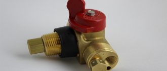
Non-return valve (siphon) for air conditioner. Designed to connect the drainage pipeline to the central sewerage system
Check valves, which are installed in air conditioning systems, simultaneously solve two important problems:
- provide targeted passage of refrigerant from the warm part of the evaporator to the cold part;
- prevent the formation of reverse condensation.
Such devices are very actively used in ventilation, where they also solve several problems:
- improving draft in the ventilation system if it consists of several branched sections;
- preventing cold air from entering the premises from the street;
- protection of premises served by the ventilation system from foreign odors;
- protection of industrial premises from toxic and explosive atmospheres entering their atmosphere;
- preventing combustion products from entering the premises if a fire occurs in the building in which such premises are located.
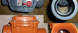
The check valve for ventilation is a blade mounted on an axis
The reverse-action air damper used in ventilation systems is installed not only in industrial and office buildings, shopping centers and other public buildings, but also in apartment buildings. It protects apartments from foreign odors by cutting off the flow of air coming from outside.
Operating principle of a check valve
The valve design is a protective device to prevent the appearance of reverse ventilation draft in the apartment. By allowing the flow of fresh air to flow in the desired direction, the valve inhibits the reverse movement of the flow.
The main advantage of the design is its automatic operation.
The absence of a check valve will not only pollute the room with exhaust air, get dust and insects inside, but also lead to the appearance of drafts
In ventilation systems, the valve prevents air from entering the common ventilation duct into individual rooms. Such designs work in systems with both natural and mechanical traction.
Such situations may arise due to the following problems:
- incorrect installation of the exhaust pipe;
- insufficient supply of fresh air to the system;
- installation of forced ventilation in one of the apartments;
- check valve malfunction.
The main structural element of a check valve is the shutter. When the valve is installed correctly, the valve should open under air pressure in one direction only.
When air moves not from the room, but into it, the shutter automatically closes.
DIY compressor unloader valve
Favorable operating conditions for the compressor can be ensured by installing special devices, for example, a check valve.
Today it is included in the delivery of most compressors, but from time to time they have to be replaced.
Let's take a closer look at the features of the mechanism, as well as its purpose.
Pressure switch for compressor. Connection and setup
Budget models of air compressors are not always equipped with a pressure switch, since similar devices are installed on the receiver.
Therefore, manufacturers of this equipment believe that visual monitoring of the pressure developed by the compressor based on pressure gauge readings is quite sufficient.
At the same time, during long-term work, in order to avoid engine overheating, it is advisable to install a pressure switch on the compressor.
Then the drive will turn on and off automatically.
Possibility of making it yourself
There is no deep material meaning to independently manufacturing valves; purchasing parts will cost almost more than a ready-made commercially produced valve. Or the workshop at home must have precision drilling, turning and milling machines for independent production of device parts.
Very often, home craftsmen make valves with their own hands to test their own strength in design and assembly. We also produce original valves for domestic innovative beverage production plants or aquarium filtration and aeration systems. Next, the design and production technology of the valves will be considered:
- Ball for water.
- Gravity ball for water.
- Disc-shaped.
- Petal for ventilation.
Figure 3. Reed air valve design
The designs are simple and the technology does not require the use of expensive equipment. It is quite possible to make a simple check valve in a workshop at home. It is enough to have an average level of locksmithing skills.
Check valve
A check valve (return valve) is a device that allows compressed air to flow in only one direction . Structurally, it is assembled (see figure) in a metal case (item 3), inside of which the following are located:
- internal shutter (item 6), blocking the inlet;
- a spring (pos. 4) pressing the rubber ring (pos. 5) to the bolt seat;
- inlet fitting (pos. 7);
- plug (item 1) with a sealing gasket made of cardboard (item 2) (the plug makes it possible to disassemble the return for repair or maintenance).
On a note! The check valve has a branch for connecting it to the receiver and a small branch for connecting a pressure switch.
Operating principle
The reverse action valve works as follows. Passing through the outlet valve of the piston cylinder, the compressed air enters the return pipe through the inlet fitting (pos. 7). Having reached a certain pressure, the air lifts the internal shutter (pos. 6) and passes through the cavity in the housing (pos. 3) into the storage tank of the receiver. When the compressor is turned off, the spring (item 4) returns the internal shutter to its place, blocking the path of air from the receiver back into the piston cylinder.
Varieties
On the domestic market you can find compressors with returns made of three different materials: aluminum, plastic and brass. At the same time, the aluminum part differs from its analogues in its high reliability and durability. It is built inside the air duct that connects the piston cylinder to the receiver, and is capable of operating under high temperature conditions (up to 200°C). Whereas a plastic return line is installed in budget models operating at a low temperature of the working environment. As for valves made of brass, they are widely used. Such return valves are quite reliable and perfectly maintain their performance characteristics in cases where the air temperature during compression does not exceed 140°C.
Recommendations for selection
If the compressor return line fails, it is not difficult to replace it with a similar one. However, before you buy a new valve, you need to pay special attention to the diameter of the threads cut on the outlets of its body . After all, the connecting dimensions of the return, compressor and receiver may differ from each other.
Advice! When going for a new check valve for your compressor, do not forget to take the failed part with you. This will greatly facilitate the selection procedure for a new node.
It is also necessary to take into account the technical characteristics and operating conditions of the compressor. After all, there are valves that are not designed to work with high-pressure compressor equipment. In addition, when the working medium heats up to a high temperature during compression, the use of plastic returns is impractical - it is better to purchase a unit in a metal case, which is mounted inside the air duct connecting the compressor and the receiver. It will not be superfluous to purchase a collapsible design - this will allow you to buy the appropriate repair kit in the future and fix the return fault yourself, replacing the failed parts with purchased spare parts.
Making a check valve yourself
In cases where it is not possible to purchase a new check valve to replace a faulty one, you can make it yourself from scrap materials. For this you will need:
- female tee;
- spring;
- 2 couplings with external thread, the diameter corresponding to the internal thread of the tee;
- a ball whose diameter is larger than the size of the internal hole in the coupling;
- a metal plug with an external thread that matches the internal thread on the tee.
The valve is assembled in the following sequence: first, the coupling is screwed into one of the branches of the tee, then a ball is inserted into the tee on the other side, and then the plug is screwed in, pressing the ball with a spring.
There are several practical tips for making a return line.
- It is best to take the ball from an old computer mouse - it has a rubberized surface that will fit more tightly to the edges of the hole.
- You can also use a regular piece of pipe of suitable diameter as a body. True, in this case you will have to drill a side hole in it, weld another bend and cut threads at all ends.
- The spring must press the ball with a certain force and in no case should it be weakened.
Safety valve
The relief valve (another name is safety) valve serves for emergency release of pressure and is the final device that protects the pneumatic equipment connected to the compressor from damage.
Attention! It is not recommended to operate the compressor without a safety valve.
Experts also include the following types of relief valve:
- bypass valve;
- unloading valve.
Despite minor design differences, their operating principle is identical to a safety valve.
Operating principle of the safety valve
Compressor equipment that is not intended for use in industrial environments is equipped with spring-loaded safety valves. When such a compressor operates in normal mode, it is closed (see diagram). In this case, the air pressure on its plate is balanced by a calibrated spring, which prevents the locking mechanism from opening. If the pressure suddenly increases above the set value, the pressing force of the plate against the nozzle decreases and the valve begins to open. This releases excess air, after which the locking mechanism can return to its place.
Important! If the relief valve does not return to its place for a long time, then the compressor must be turned off and the cause that caused the unauthorized increase in pressure must be eliminated
Bypass valve
The bypass (or overflow) valve maintains the pressure of the working medium at a given level. To do this, through the existing branch there is a constant, and not one-time or periodic, as in a safety valve, removal of an excess amount of the working medium (compressed air, gas, liquid), which ensures pressure stability in the system. Such valves are used, for example, in turbochargers installed on automobile internal combustion engines.
Unloading valve
The unloading valve ensures the release of compressed air remaining in the manifold between the piston block and the return line when the compressor stops. In this case, the pressure at the compressor outlet is reduced to atmospheric pressure. In general, the presence of an unloading valve makes it possible to:
- relieve pressure in the line when the compressor is turned off;
- transfer the compressor to zero capacity in the absence of flow of working fluid;
- facilitate restarting of both the compressor and the connected pneumatic equipment.
In addition, the unloading valve is used in cases where it is not possible to turn off the mechanical drive of the connected pneumatic equipment . Install it at the compressor outlet in front of the return line.
So, the more productive and powerful the compressor equipment, the more complex the valve system. The simplest check valve for use in a household low-pressure compressor can be made by yourself. But for the installation to work correctly, it is recommended to purchase a factory-made part.
Main varieties
Check valve systems, depending on their design, can be:
- straight type;
- corner;
- spring;
- ball;
- installed using flanges;
- casement;
- mounted by soldering;
- manufactured for disassembly.
Direct type check valve for high pressure stations
The material of manufacture may also vary, which depends on what media such a device will come into contact with during operation. In particular, it can be either metal alloys of various types or plastic.
Depending on the type of shut-off element used, check valves can be:
- with a shut-off element made in the form of a flat valve;
- ball;
- membrane;
- petal;
- with gravity grid.
The last three types of devices are used for installation in ventilation systems. Among check valves and safety valves installed on compressors, ball-type devices are the most popular, since they are less critical to contaminants present in the working environment.
Check valves with cone (a), flat (b) and spherical (c) shut-off elements
Among the most modern valve systems, it is worth noting electromagnetic type devices, in which the movement of the valve is controlled not by a spring, but by an electromagnet. Meanwhile, due to the rather high cost and not too much reliability, such devices are not very popular, inferior to cheaper and time-tested spring analogues.
Recommendations for selection
When choosing a check valve, you should consider a number of parameters. These include, in particular:
- the intensity of the air flow that will be transported through the system;
- the performance of the air exchange device on which the check valve will be installed;
- the power of the air pumping device, which can be a compressor or fan;
- the degree of contamination of the working environment that will be transported through the elements of the system being created;
- temperature operating conditions.
In addition, it is necessary to take into account the type of medium with which the elements of the valve device will come into contact. This parameter has a direct impact on the choice of valve material, which must have the required durability.
Troubleshooting methods
More complex work will be required if the compressor does not turn on. This can happen if the relay contacts wear out and melt from sparks that occur when the electric current is interrupted. Two methods are possible:
- In case of slight wear of the contact groups, clean the areas with a file or sandpaper. Care must be taken not to bend the slats. This will extend the service life by several weeks.
- Replace the contact groups with new ones from the repair kit for this model.
To repair contact groups, the following operations should be performed:
- Bleed the air from the tank and disconnect the unit from the network.
- Remove the relay from the compressor.
- Remove the casing.
- Disconnect the wires going to the contacts.
- Using a screwdriver, pry the contact terminal out of the mount and carefully drill out the melted areas.
- The wire is replaced with copper wire of the appropriate cross-section. It should fit into the hole with minimal clearance. The wire is passed into the hole and pressed tightly with pliers.
- After repairing all melted contacts, reassemble the device in the reverse order.
It makes sense to spend time on such repairs only if branded spare parts are unavailable for replacement.
I made and adjusted the air pressure switch for the compressor myself: find out how
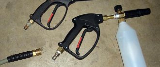
The Russian market offers potential consumers a large number of different tools. Analyzing the state of the market, experts note a slight increase in the popularity of pneumatic tools.
However, while surpassing traditional types of power tools in basic parameters (power, reliability, durability), pneumatic tools require a source of compressed air.
Such a source is an air compressor, the purchase of which for one-time work is not economically feasible. That is why, widely used by professionals, pneumatic tools are rarely used in everyday life.
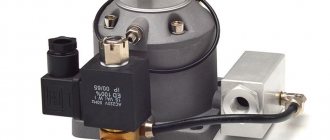
It is this device that regulates the air pressure in the compressor
Structurally, an air compressor is a device that can be manufactured by a person who has certain knowledge and skills in performing plumbing and electrical work at home. The responsible unit is an air pressure switch (pressostat), which you can install and adjust yourself. In addition, you can independently eliminate the simplest malfunctions of the pressure switch.
Pressure switch: purpose and principle of operation
A pressure switch is a device (actuator) with which the compressor motor is turned on or off. It is mounted on the tank (receiver) and connected to its check valve and the compressor head.
The pressure switch ensures that the entire product operates automatically. With its help, the required air pressure in the receiver is maintained.
The operating principle of such a relay is to use a normally closed contact in the electrical motor control circuit. Depending on the amount of air pressure in the pneumatic system, the power supply circuit is closed or opened. In this case, the engine starts with insufficient air pressure or is de-energized when the maximum value is reached.
As a working mechanism of the pressure switch, springs of different stiffness are used, which react differently to changes in air pressure in the receiver. The actuator is activated due to the forces of elastic deformation of the springs as a result of the pressure of the compressed air located in the receiver. In this case, the contact of the engine power supply circuit is closed or opened.
Accessories
In general, the pressure switch kit includes (maximum configuration):
- Unloading valve.
- Thermal motor protection relay.
- Mechanical switch.
- Safety valve.
The safety valve is an important element of the pressure switch
Each of these devices performs specific functions:
- Unloading valve - opens when the engine is stopped and relieves pressure from the pneumatic line. The next time the electric motor is turned on and accelerates, the check valve is locked, which makes it easier to start the entire device from the off state.
- Thermal motor protection relay - limits the current in the windings. A special adjusting element sets the permissible current strength, exceeding which will lead to shutdown of the electric motor.
- Mechanical switch - turns on the automatic operating mode of the product (AUTO position) and allows you to forcibly turn off the engine (OFF position).
- Safety valve - is activated if the compressor pressure switch fails and produces an emergency release of compressed air from the receiver, preventing pressure from increasing above the permissible value.
Connection diagram
Existing air pressure switches for a 220 V compressor are used in various load connection schemes.
- In the case of using a single-phase electric motor, use a pressure switch with two contact groups, designed to operate in a 220 V network.
- If there is a three-phase motor, a relay with an operating voltage of 380 V, equipped with three contact groups, is used.
ATTENTION! It is not recommended to use a single-phase air pressure switch (220 V) to connect a three-phase motor.
The pressure switch is connected to the electrical circuit of the compressor using special contactors (connectors) built into its housing.
Connecting flanges
The pressure switch is connected to the receiver using a threaded flange with a standard 1/4 inch internal thread. Many pressure switches are equipped with a 4-sided flange, which allows, if necessary, to connect up to three additional devices to it, for example:
- Pressure gauge.
- Safety valve.
- Unloading valve.
If there is no need to connect additional devices, then the flanges are closed with special plugs.
IMPORTANT: Flange threaded holes are 3/8" or 1/2" threaded. Additional devices must also have appropriate threads.
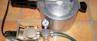
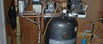
Receiver, relay - all assembled, excellent compressor
Installation
The compressor pressure switch is mounted directly on the compressor tank (central flange with 1/4 inch thread). If necessary, additional devices are installed through loose flanges. If there is no need for additional devices, then the threaded holes of the flanges are closed with special plugs.
The control circuit for turning the compressor motor on and off is connected to the contacts of the pressure switch.
ATTENTION! If the load current exceeds the permissible power of the relay contacts, it is necessary to use a network contactor (magnetic starter) when connecting.
Settings
Serially produced pressure switches do not require adjustment. However, during the operation of the compressor, situations may arise in which it is necessary to change the response thresholds of its actuator. The procedure for performing adjustment work:
- Determine the range of change in compressed air pressure.
- Disconnect the product from the electrical network.
- Remove the top cover of the pressure switch.
- Set the required values of the relay response thresholds using two special adjusting spring-loaded screws located under the cover. The set values are controlled using a pressure gauge.
- Adjustment of the upper threshold of the pressure switch, at which the electric motor is turned off, is carried out using the adjusting screw, marked with the symbol “P”. To change the response threshold of the actuator, it is necessary to rotate the screw in the direction of the arrow in the direction corresponding to the designations “+” and “-“.
- Setting the lower threshold of the pressure switch, at which the engine will automatically turn on, is done by rotating the second adjusting screw with the symbol “5P” towards the designations “+” and “-“.
- Reinstall the top cover of the air pressure switch.
DIY pressure switch
Having taken on the task of making an air compressor on their own, some amateur craftsmen may decide to make a pressure switch with their own hands.
Making your own equipment is interesting, practical and very economical
On the Internet you can find options for homemade devices, for example, made from a thermostat from a refrigerator or made using parts from CDs and plastic bottles.
However, it should be noted that their design cannot be compared with the design of a commercially produced compressor pressure switch.
In addition, the use of a homemade device, in the event of a sudden failure, can lead to an emergency with unpredictable consequences for others.
TIP: given that the air pressure switch is one of the most critical components of the compressor, it is better to install an industrial pressure switch even in a homemade compressor.
Relay malfunctions and their elimination
There are several characteristic faults inherent in pressure switches. Most often, in these cases, the relay is simply replaced with a new one, but there are also breakdowns that can be fixed with your own hands. Among them the most common are:
- Air leakage through the pressure switch when the compressor stops. The cause of the malfunction is contamination of the receiver check valve. To eliminate the malfunction, it is necessary to bleed the compressed air from the reservoir, remove the valve plug and clean the valve seat and O-ring.
- When the compressor is operating, compressed air leaks through the pressure switch. This is due to a breakdown of the start valve. The malfunction is eliminated by replacing the start valve gasket.
- The compressor starts to turn on frequently. This occurs due to vibration of the compressor and a shift in the position of the adjusting screws. It is necessary to check the thresholds for turning on and off the pressure switch and adjust them according to the instructions given in the “Settings” section.
- The compressor does not turn on. In this case, there may be several reasons, but one of them is related to the burning of the contact group of the pressure switch. Burning of contacts occurs due to electric spark erosion that occurs when the contact group opens.
You can fix the problem:
- replacing the pressure switch;
- by cleaning the contacting surfaces (extends the life of the device by 2-3 months);
- replacing the contact group with a new one (not all modifications are commercially available);
- by repairing the contact group yourself (replacing contacts in the terminals).
DIY contact group repair
Having started the repair, it is necessary to bleed the air from the receiver, turn off the power to the compressor and dismantle the pressure switch. Repair work is carried out in the following order:
- Remove the protective cover.
- Disconnect the wires going to the contact group.
- Using a flat-head screwdriver, remove the contact group and terminal holder. You need to remember the position of the return spring, which can “shoot” when dismantling the contact group. Pull the terminals out of the holder and drill out the burnt contacts from them.
- Take a piece of copper wire 10 mm long and insert it into the drilled hole. The diameter of the wire should ensure a tight fit in this hole.
- Crimp the wire on both sides in such a way as to ensure its secure fastening in the hole.
- If necessary, repeat the same procedure with the remaining terminals.
- Assemble the contact group by performing the necessary operations in reverse order.
- Place the contact group in place and close the pressure switch with the lid.
WATCH VIDEO INSTRUCTIONS
INTERESTING: a service representative who came to fix a compressor malfunction will insist on replacement if the pressure switch breaks. He will not clean or change the parts of the contact group, since performing such work will cost the consumer more than purchasing and installing a new one.
Making a check valve for my SO-7B compressor (any compressor..)
I prepared this article for homemade people.
While inadequate people and mischief-makers of various breeds are trying to convince sane people in the comments to my articles on political topics that I am an FSB agent and at the same time an agent of the State Department (you can read it, it’s a laugh))), I don’t deliberately delete any comments, even the most disgusting ones, I myself am very I want to know who I am, after all)), I’ll tell those who, like me, out of necessity make various things and devices with their own hands, how I made a check valve for my compressor unit. Why I decided to write about this - simply when there was a need for this component to assemble my compressor - this: I didn’t find a suitable option for myself: either the design was not satisfactory (for example, some install water pipes or similar homemade ones, but the valve “slams” and, they write, is often destroyed), or the installation method (the design that I really liked, and had the opportunity to order, was made from an aluminum blank using milling and was designed for installation inside the tank, and I didn’t want to cut my own again, and + the price is steep, and + shipping..). I decided to make my own welded one from the most affordable “semi-finished products” and with the design of the valve itself, borrowed from the same SO-7B compressor (I also make these parts for myself, it’s very expensive to buy) for unification. Everything was done with a grinder, welding, drill and file.
In the photo, from left to right, you can see the entire structure of the valve “capsule”: the plug (an adapter can be external 1 1/2 - internal 3/4 or 1/2) is drilled and bored to weld in a 3/4 coupling, then a piece of 3/4 tube about 160 mm long, on one side there is a thread (can be cut on a tube, but I just have a short one welded), on the other there is a bevel and a plate welded to the bevel in the shape of a bevel 4 mm thick - the plane of contact and fastening of the plate valve (with a slot and threaded mounting holes). Next - a glass: half of the 1 1/2 coupling is welded to a piece of pipe (the diameter and length are such that the previous part with the valve assembly attached to it fits freely and can rotate when screwed in (I had a piece with an outer diameter of 50mm), then it is welded to the end a large washer and a piece with a 3/4 external thread. I used all the “semi-finished products” from ordinary steel, not cast iron - with cast iron I didn’t want unnecessary fuss when welding.
Source