What does the standard regulate?
The rules under consideration relate to the mechanical engineering industry and regulate the execution of connections of steel pipes, and also set the defining dimensions.
The main provisions established by the document:
- classification of pipe connections;
- parameters of edge bevels and their number;
- weld width;
- cross-section geometry;
- minimum permissible pipe wall thickness;
- geometric parameters of structural elements;
- design legs for fillet welds;
- surface roughness;
- material for the manufacture of couplings and linings;
- clearances allowed in various areas of the structure;
- tolerances, maximum deviations.
Thus, when carrying out arc welding work, the characteristics of the pipe connection are fully described in this document.
The production of the pipes themselves is not covered by the GOST in question.
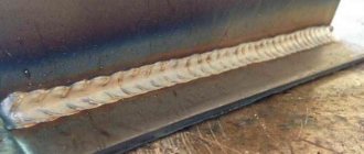
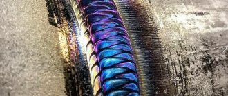
Types of Welds
Butt welds are used when welding circumferential joints of pipes in accordance with GOST. Such compounds are designated C1-C53
They are made single- and double-sided, with straight and rounded beveled edges and with boring.
Single-sided seams may have a removable or retained backing, as well as a fusible insert.
Sector connections at pipeline turns are made with beveled edges and are designated C54-C55.
Flange and pipe connections are designated as C56
An example of the designation of a U2 type corner connection.
Fillet welds are designated U5-U21, lap welds H1-H4
The meaning of the parts to be welded
The welded parts play an important role in obtaining a high-quality and durable connection. The main significance here is the heterogeneity of the thickness of the various structural elements to be combined and the roughness of the surfaces that are processed before welding.
This state standard reveals the following aspects that need to be taken into account when manufacturing the product:
- When making tees from steel pipes, you should use the seams and types of connections specified for branches with pipes, and in the case of assembling crosses, transitions with pipes, the corresponding assemblies of pipe with pipe or pipe with flange.
- If the thickness is different, but does not exceed the difference values (see Table 1), welding is allowed in the same way as for elements of the same thickness. Nevertheless, the dimensions of the seam and the types of edges must be selected according to the thickness of the larger part. To ensure a smooth transition from one element to another, the seam surface may be positioned at an angle.
- If the difference in the wall thickness of the pipes being connected exceeds the values given in Table 1, then the part with a greater thickness must be beveled so that it matches the thickness of the thinner part. The dimensions of the weld must be selected according to the part with a smaller thickness.
- The roughness of the surfaces to be processed is Rz up to 80 microns.
- Shims and couplings used when making a weld must be made of the same steel as the parts being welded. If the elements are made of carbon metal, then it is possible to make them from steel 20 or 10.
- When performing inspection using radiography, the gap between the pipe being welded and the remaining lining is determined - it should not be more than 0.2 mm. If the connection is not subject to radiographic testing, the gap does not exceed 0.5 mm. Local clearances of up to 0.5 mm and up to 1 mm, respectively, are allowed for the designated connections.
- When welding pipes, a meltable insert is used; the gap between it and the inner or side edge of the pipe should not exceed 0.5 mm.
We recommend reading Features of flux-cored wire welding
Table 1
| Thickness of thin part | Thickness difference |
| Until 3 | 1 |
| From 3 to 7 | 2 |
| From 7 to 10 | 3 |
| From 10 | 4 |
Careful preparation of parts before welding and establishing their compliance with the technical conditions of this GOST will make it possible to produce a welded joint of proper quality.
SNiP III-42-80: Assembly, welding and quality control of welded joints of pipelines
General provisions Preparatory work Earthwork
4.1. Before assembling and welding pipes, you must:
carry out a visual inspection of the surface of the pipes (in this case, the pipes should not have unacceptable defects regulated by the technical conditions for the supply of pipes);
clean the internal cavity of the pipes from soil, dirt, and snow that has gotten inside;
straighten or trim deformed ends and damaged pipe surfaces;
Clean the edges and adjacent inner and outer surfaces of the pipes to a width of at least 10 mm to bare metal.
When flash butt welding, you should additionally clean the end of the pipe and the belt under the contact shoes of the welding machine.
4.2. It is allowed to straighten smooth dents at the ends of pipes with a depth of up to 3.5% of the pipe diameter and deformed ends of pipes using shockless expanding devices. At the same time, on pipes made of steel with a standard tensile strength of up to 539 MPa (55 kgf/mm2), it is allowed to straighten dents and deformed pipe ends at positive temperatures without heating. At negative ambient temperatures, heating is required at 100-150°C. On pipes made of steel with a standard tensile strength of 539 MPa (55 kgf/mm2) and more - with local heating at 150-200 ° C at any ambient temperature.
Sections and ends of pipes with a dent depth of more than 3.5% of the pipe diameter or with tears must be cut out.
Repair by welding of nicks and burrs of chamfers up to 5 mm deep is allowed.
The ends of pipes with nicks and chamfers with a depth of more than 5 mm should be cut off.
4.3. The assembly of pipes with a diameter of 500 mm or more must be carried out on internal centralizers. Smaller diameter pipes can be assembled using internal or external centralizers. Regardless of the diameter of the pipes, the assembly of overlaps and other joints where the use of internal centralizers is impossible is carried out using external centralizers.
4.4. When assembling pipes with the same standard wall thickness, displacement of the edges is allowed by up to 20% of the pipe wall thickness, but no more than 3 mm for arc welding methods and no more than 2 mm for flash butt welding.
4.5. Direct connection on the route of pipes of different thicknesses of the same diameter or pipes with parts (tees, transitions, bottoms, bends) is allowed under the following conditions:
if the difference in wall thicknesses of joined pipes or pipes with parts (the maximum of which is 12 mm or less) does not exceed 2.5 mm;
if the difference in wall thicknesses of joined pipes or pipes with parts (the maximum of which is more than 12 mm) does not exceed 3 mm.
The connection of pipes or pipes with parts with a greater difference in wall thickness is carried out by welding between the joined pipes or pipes with parts of adapters or inserts of intermediate thickness, the length of which must be at least 250 mm.
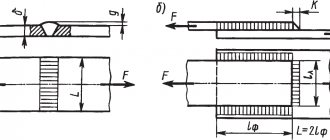
With a thickness difference of up to 1.5 times the thickness, direct assembly and welding of pipes is allowed with special cutting of the edges of the thicker wall of the pipe or part. The design dimensions of the edges and welds must correspond to those shown in Fig. 1.
The displacement of the edges when welding pipes of different walls, measured along the outer surface, should not exceed the tolerances established by the requirements of clause 4.4 of this section.
Welding from the inside of the root of the weld of pipes with different walls with a diameter of 1000 mm or more along the entire perimeter of the joint is mandatory, in this case the welding layer must be cleaned of slag, electrode cinders and slag must be collected and removed from the pipe.
Rice. 1. Structural dimensions for cutting edges and welds of pipes of different thicknesses (up to 1.5 wall thickness)
4.6. Each joint must have the mark of the welder or team of welders performing the welding. At joints of steel pipes with a standard tensile strength of up to 539 MPa (55 kgf/mm2), marks must be applied mechanically or by surfacing. Joints of steel pipes with a standard tensile strength of 539 MPa (55 kgf/mm2) and more are marked with indelible paint on the outside of the pipe.
The marks are applied at a distance of 100-150 mm from the joint in the upper semicircle of the pipe.
4.7. Welding of any elements, except for cathode leads, in the locations of transverse annular, spiral and longitudinal factory welds is not allowed. If the project provides for welding elements to the pipe body, then the distance between the seams of the pipeline and the seam of the welded element must be at least 100 mm.
4.8. Direct connection of pipes with shut-off and distribution valves is permitted provided that the thickness of the welded edge of the fitting nozzle does not exceed 1.5 times the wall thickness of the pipe being joined to it in the case of special preparation of the edges of the fitting nozzle in the factory according to Fig. 2.
In all cases when the special cutting of the edges of the fitting pipe is not carried out in the factory, and also when the thickness of the welded edge of the fitting pipe exceeds 1.5 times the wall thickness of the pipe being joined to it, the connection should be made by welding a special adapter or adapter ring between the pipe being joined and the fittings .
Rice. 2. Preparation of wet fittings for fittings when directly connecting them to pipes
4.9. When welding a pipeline into a thread, the welded joints must be tied to the pickets of the route and recorded in the as-built documentation.
4.10. If there is a break in work for more than 2 hours, the ends of the welded section of the pipeline should be closed with inventory plugs to prevent snow, dirt, etc. from getting inside the pipe.
4.11. Circular joints of steel main pipelines can be welded using arc welding methods or flash butt welding.
4.12. It is allowed to carry out welding work at air temperatures down to minus 50°C.
When the wind exceeds 10 m/s, as well as during precipitation, it is prohibited to carry out welding work without inventory shelters.
4.13. Installation of pipelines should only be carried out on mounting supports. The use of soil and snow prisms for pipeline installation is not permitted.
4.14. Welders who have passed exams in accordance with the Rules for Certification of Welders of the Gosgortechnadzor of Russia, have certificates and have passed the tests regulated by the requirements of paragraphs are allowed to tack and weld main pipelines. 4.16—4.23 of this section.
4.15. The production of welded pipeline connecting parts (bends, tees, transitions, etc.) in the field is prohibited.
4.16. When performing welding work, each welder (team or link of welders in the case of welding a joint by a team or link) must (must) weld a permissible joint for pipes with a diameter of up to 1000 mm or half a joint for pipes with a diameter of 1000 mm or more under conditions identical to the welding conditions on route if:
he (they) started welding the main pipeline for the first time or had a break in his work for more than three months;
pipe welding is carried out from new steel grades or using new welding materials, technology and equipment;
the diameter of the pipes for welding has changed (transition from one group of diameters to another - see a - c in Fig. 3);
The shape of the pipe ends for welding has been changed.
Rice. 3. Scheme of cutting samples for mechanical tests
a - pipes with a diameter of up to 400 mm inclusive; b - pipes with a diameter from 400 mm to 1000 mm; c - pipes with a diameter of 1000 mm or more; 1—sample for tensile testing (GOST 6996-66, type XII or XIII); 2 - sample for bending with the root of the seam outward (GOST 6996-66, type XXVII or XXVIII) or on the edge; 3 - sample for bending with the root of the seam inward (GOST 6996-66, type XXVII or XXVIII) or on the edge
4.17. The permissible joint is subjected to:
visual inspection and measurement, in which the weld must meet the requirements of paragraphs. 4.26; 4.27 of this section;
radiographic control in accordance with the requirements of clause 4.28 of this section;
mechanical tests of samples cut from a welded joint in accordance with the requirements of clause 4.19 of this section.
4.18. If the joint does not meet the requirements of paragraphs 4.26, 4.27, 4.32 of this section by visual inspection and measurement or by radiographic control, then welding and re-inspection of two other permissible joints are performed; If, during repeated inspection, unsatisfactory results are obtained at at least one of the joints, the team or individual welder is recognized as having failed the test.
4.19. Mechanical tests involve checking tensile and bending samples cut from welded joints. The cutting pattern and the required number of samples for various types of mechanical tests must correspond to those shown in Fig. 3 and in table. 3.
Table 3
| Pipe diameter, mm | Number of samples for mechanical testing | ||||
| tensile | for bending with the location of the root of the seam | Total | |||
| outward | inside | on the edge | |||
| Wall thickness, pipes up to 12.5 mm inclusive | |||||
| Up to 400 mm | 2 | 2 | 2 | — | 6 |
| St. 400 mm | 4 | 4 | 4 | — | 12 |
| Pipe wall thickness over 12.5 mm | |||||
| Up to 400 mm | 2 | — | — | 4 | 6 |
| St. 400 mm | 4 | — | — | 8 | 12 |
Samples for mechanical testing must be prepared in accordance with the requirements of GOST 6996-66 and these building codes and regulations.
4.20. The tensile strength of a welded joint, determined on tensile specimens with the reinforcement removed, must be no less than the standard value of the tensile strength of pipe metal.
4.21. The arithmetic mean value of the bending angle of samples welded by arc welding methods must be at least 120°, and its minimum value must be at least 100°.
4.22. The arithmetic mean value of the bending angle of samples welded by flash butt welding must be at least 70°, and its minimum value must be at least 40°. When calculating the average, all angles greater than 110° are considered equal to 110°.
4.23. If the samples cut from the joint have unsatisfactory mechanical properties in accordance with the requirements of paragraphs. 4.20—4.22 of this section, then tests are carried out on twice the number of samples cut from the re-welded joint; If unsatisfactory results are obtained during repeated testing, the welding team or individual welder is recognized as having failed the test and must undergo retraining.
4.24. Inspection of welded joints of pipelines is carried out:
systematic operational control carried out during the assembly and welding of pipelines;
visual inspection and measurement of welded joints;
checking welds using non-destructive testing methods;
based on the results of mechanical tests of welded joints in accordance with clause 4.29 of this section.
4.25. Operational control should be carried out by work producers and foremen, and self-control by work performers.
During operational control, the compliance of the work performed with the working drawings, the requirements of this section, state standards and instructions approved in the prescribed manner must be checked.
4.26. Joints made by arc welding are cleaned of slag and subjected to external inspection. At the same time, they should not have cracks, undercuts more than 0.5 mm deep, unacceptable displacements of edges, craters and pores extending to the surface.
The reinforcement of the seam should be in the range of 1 to 3 mm in height and have a smooth transition to the base metal.
4.27. Joints made by flash butt welding, after removing the internal and external flash, must have reinforcement with a height of no more than 3 mm. When removing internal and external burrs, it is not allowed to reduce the thickness of the pipe wall.
The displacement of the edges after welding should not exceed 25% of the wall thickness, but not more than 3 mm. Local displacements of 20% of the joint perimeter are allowed, the value of which does not exceed 30% of the wall thickness, but not more than 4 mm.
4.28. Installation welded joints of pipelines and their sections of all categories, made by arc welding, are subject to control by physical methods in the amount of 100%, of which only welded joints by radiographic method:
sections of pipelines of categories B and I in all regions and regardless of diameter;
pipelines with a diameter of 1020-1420 mm and their sections in the regions of Western Siberia and the Far North;
pipeline sections at crossings through swamps of types II and III in all areas;
pipeline sections at crossings through railways and roads of categories I, II and III in all regions;
pipelines in areas of their overhead passages, overlaps, welded inserts and fittings.
pipeline sections indicated in positions 6, 9, 10, 18, 20 and 23 of Table 3 of SNiP 2.05.06-85*.
In other cases, installation welded joints of pipelines and their sections are subject to control for categories II, III and IV by the radiographic method in a volume of at least 25, respectively; 10 and 5%, and the remaining welded joints - by ultrasonic or magnetographic method.
Corner welded joints of pipelines are subject to 100% ultrasonic inspection.
Table 4 has been removed.
4.29. Welded connections of pipelines of categories I, II, III, IV, made by flash butt welding, are subject to:
100% control by physical methods based on registered parameters of the welding process.
mechanical tests in the amount of 1% of joints in accordance with paragraphs. 4.20, 4.22 of this chapter in order to check the condition of the automatic control system for the welding process.
4.30. If the results of mechanical tests of welded joints are unsatisfactory, it is necessary to:
stop welding, establish the reason for the unsatisfactory quality of the welded joint;
subject the entire section of the pipeline, welded since the last inspection by the installation organization in the presence of representatives of the customer’s technical supervision, to bending force to create (in the upper and lower parts of each joint) a stress equal to 0.9 of the standard yield strength.
Work can be continued by this welder on the same installation only after setting up the automatic process control system and after obtaining satisfactory results from an additionally welded and checked tolerance joint in accordance with the requirements of paragraphs. 4.17, 4.19, 4.20, 4.22.
4.31. In addition to the established standards for the number of welded joints subjected to control by physical methods and mechanical tests, individual welded joints assigned to control by representatives of the customer’s technical supervision, the State Mining and Technical Supervision Authority of Russia, can also be subject to inspection.
4.32. When inspecting pipeline joints made by arc welding using physical methods, welds in which:
there are no cracks of any depth or length;
the depth of slag inclusions does not exceed 10% of the pipe wall thickness with their total length not exceeding 1/6 of the joint perimeter;
the largest pore size as a percentage of the pipe wall thickness does not exceed 20% with a distance between adjacent pores of at least 3 wall thicknesses; 15% with a distance between adjacent pores of at least 2 wall thicknesses; 10% when the distance between adjacent pores is less than 2 wall thicknesses, but not less than 3 times the pore size; 10% when the distance between adjacent pores is less than 3 times the pore size in areas with a total length of no more than 30 mm per 500 mm of seam.
In all cases, the maximum pore size should not exceed 2.7 mm.
Natural lack of penetration at the root of the joint is allowed with a depth of up to 10% of the pipe wall thickness, but not more than 1 mm, with a total length of up to 1/6 of the joint perimeter.
In pipeline joints with a diameter of 1000 mm or more in sections made with internal welding, lack of penetration at the root of the seam is not allowed.
The total length of lack of fusion along the edges and between layers in non-rotating pipe joints made by automatic arc welding should not exceed 50 mm in a weld section 350 mm long.
The total depth of lack of penetration and slag inclusions located in the same plane should not exceed 10% of the pipe wall thickness, but not more than 1 mm, while the length of the defective area should not exceed 50 mm in a weld section with a length of 350 mm.
4.33. If the results of testing by physical methods are unsatisfactory for at least one joint of category IV pipelines, an additional 25% of the welded joints from the number of joints made since the previous inspection should be checked using the same method. In this case, the welder or team that committed the defect is suspended from work until the inspection is completed. If, upon re-inspection, at least one joint turns out to be of unsatisfactory quality, the welder or team that made the defect is not allowed to perform welding work until the tests are re-taken, and the joints they welded from the moment of the previous inspection are subject to 100% radiographic control.
4.34. Correction of defects in joints made by arc welding methods is allowed in the following cases:
if the total length of the defective sections does not exceed 1/6 of the perimeter of the joint;
if the length of cracks identified in the joint does not exceed 50 mm.
If there are cracks with a total length of more than 50 mm, the joints must be removed.
4.35. Correction of defects in joints made by arc welding methods should be done in the following ways:
welding defective areas at the root of the seam from the inside of the pipe;
surfacing of thread beads with a height of no more than 3 mm when repairing external and internal undercuts;
grinding and subsequent welding of seam sections with slag inclusions and pores;
when repairing a joint with a crack up to 50 mm long, two holes are drilled at a distance of at least 30 mm from the edges of the crack on each side, the defective area is sanded completely and welded again in several layers;
Inadmissible defects discovered during an external inspection must be eliminated before testing using non-destructive methods.
4.36. All corrected sections of joints must be subjected to external inspection, radiographic testing and meet the requirements of clause 4.32 of this section. Repeated repairs of joints are not permitted.
4.37. The results of checking joints using physical methods must be presented in the form of conclusions. Conclusions, radiographic images, recorded results of ultrasonic flaw detection and ferromagnetic tapes from joints subjected to inspection are stored in a field testing laboratory (FTL) until the pipeline is put into operation.
4.38. Rotations of the linear part of the pipeline in the vertical and horizontal planes should be performed by elastic bending of the welded pipeline thread or by installing curved sections of bent bends.
If in certain sections of the route, in accordance with the design, it is necessary to make turns of small radius, which cannot be obtained when bending pipes on cold bending machines, the turn curves should be made from steeply curved hot bending bends and stamp-welded bends, made in accordance with SNiP 2.05.06- 85*.
4.39. Making welded oblique joints in the field is prohibited.
4.40. The radii of elastic bending of the pipeline are established by the project.
The minimum permissible bending radii are taken in accordance with table. 5.
Table 5
| Diameter of pipelines, mm | Minimum permissible radii of elastic bending of the pipeline, m | Diameter of pipelines, mm | Minimum permissible radii of elastic bending of the pipeline, m |
| 1400 | 1400 | 600 | 600 |
| 1200 | 1200 | 500 | 500 |
| 1000 | 1000 | 400 | 400 |
| 800 | 800 | 300 | 300 |
| 700 | 700 | 200 | 200 |
4.41. Elastic bending of a thread-welded pipeline should be performed directly when laying it in a trench dug according to the project.
4.42. Bent bends can be manufactured in basic, factory conditions directly at the place of installation in a trench from individual pipes or two-pipe sections.
4.43. Only straight-seam and seamless pipes are subject to cold bending.
Unified radii of bent bends are established in accordance with table. 6.
Table 6
Pipe diameter, mm
Unified radii of bends when bending pipes in a cold state, m
1420
16—20
12—15
| Pipe wall thickness, mm | ||
| 60 | ||
| 1220 | 60 | |
| 1020 | 10—14 | 40 |
| 720—820 | 8—12 | 35 |
| 529 | 7—10 | 25 |
| 426 | 6—12 | 20 |
| 219-377 | 4—25 | 15 |
| Notes: 1. The specified radii apply only to the curved part of the bend. 2. The deviation of the radius value is allowed by ±5%. |
4.44. When cold bending pipes and double-pipe sections on pipe bending machines, the longitudinal welds must be located in the neutral bending plane.
4.45. The section of the two-pipe section at a distance of at least 0.5 pipe diameters on both sides of the circumferential weld should not be subject to bending.
4.46. Pipe bending on pipe bending machines must be carried out at an ambient temperature of at least minus 20°C.
4.47. Tolerances for the manufacture of bent bends on pipe bending machines must be within the limits specified in table. 7.
4.48. Turning curves (turning angles) on the linear part of pipelines, performed using bent bends, are designed with a gradation step of 3° and in cramped route conditions - 1°.
Bent bends are manufactured with bending angles that are multiples of 3° or 1°.
4.49. The location of turning curves installed from bends is carried out in accordance with the design. It is prohibited to divide pipeline turns along a circular curve and according to average radius values.
Table 7
| Contents of the permit | Amount of deviation from the specified parameter |
| Deviation of the longitudinal weld from the neutral bending plane | Up to 100 mm |
| Dispersion of longitudinal welds of a two-pipe section | Up to 100 mm |
| Ovality of cross section: | |
| ends of bent bends | Up to 2% |
| curved part of the bend | Up to 2.5% |
| Length of non-bending sections on both sides of the circumferential weld of a two-pipe section | Not less than 0.5 pipe diameter |
| Height of smooth corrugations of bent bends | Not more than the thickness of the pipe wall, but not more than 10 mm |
| Permissible deviation of the total angle of the bent elbow from the specified value | ±0°20″ |
4.50. Installation of turning curves is carried out without trimming the straight ends of bent elbows.
4.51. If a construction gap is formed when a straight section of pipeline approaches a turning curve, then it is filled by inserting, rather than moving the curve to the laid pipeline.
Transportation of pipes and pipe sections Protection of main pipelines from corrosion with insulating coatings Laying a pipeline in a trench Construction of pipeline crossings through natural and artificial obstacles Laying pipelines in special natural conditions Electrochemical protection of pipelines from underground corrosion Cleaning of the cavity and testing of pipelines Technological communication lines of main pipelines SNiP III-42 -80 : Environmental protection
Types of welds with characteristics and standard
GOST 16037 80 “Welded joints of steel pipelines” identifies several forms of seams intended for each of them. The nature of the weld depends on the design requirements, so choosing the most suitable structure for a given area will allow you to achieve the optimal ratio of mass, strength, production and technological characteristics. There are 3 main ways to connect pipes: butt, overlap, angle.
Depending on the type of welded joint, the type of seam is selected, which is conventionally designated by two symbols - a letter (C - butt, H - lap, U - corner) and the number of the structural element. For example, C56, N3, U21.
Visual table
Below is a table of seams with sketches and dimensions of elements of welded pipe joints.
Separately about cutting pipes for welding
Cutting is the operation of forming beveled edges on a workpiece. Their presence is required on parts of large thickness for the following purposes:
- provide easy access to the root of the weld for the welder’s tool;
- enable high-quality welding of elements throughout their entire thickness.
Cutting increases material consumption due to an increase in the weld zone. Minimum indicators are observed if edge cutting is not performed.
Before preparing the pipe ends for cutting, be sure to clean them. The procedure takes place in 2 stages:
- A layer of rust, oxides, and other contaminants is removed mechanically. It is carried out with abrasive tools of varying degrees of grain, both manually and using angle grinders.
- Chemical cleaning is performed to degrease the area where the seam will be and to remove other contaminants. Organic solvents are most often used, but in some cases acid etching is used.
We recommend reading: Job Description Items for Electric and Gas Welder
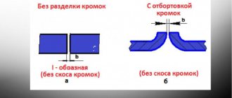
Edges can be single-sided or double-sided. According to the shape of the bevel, they are divided into V, X, and U-shaped.
The edges of the bevels must not be left sharp. With such a thickness, burns and uncooked areas may appear. To avoid this mistake, it is important to make the edge flat, creating a blunt edge, at the outermost 2 or 3 mm.
Correctly performed cutting of pipes will ensure minimization of internal stresses in the structure after completion of the work.
Welding chamfers
When joining thick pipe blanks, the formed seam should be made thicker than the part itself . To form a connection with the specified geometric parameters, it is necessary to cut the edges by chamfering. After this, the electrode will be provided with access for high-quality welding of the seam to the full depth.
The main chamfer parameters are:
- Gap b. the distance between the workpieces is up to 2-3 mm.
- Blunt C. The part of the edge that is not beveled. it is left in place to reduce the likelihood of burning through the root of the seam..
- Bevel angle β. With double-sided cutting, the acute angle takes values of 15-30°, with one-sided cutting, up to 45°.
- Cutting angle α. An obtuse angle is equal to twice the bevel angle and provides proper access to the root of the weld for welding equipment.
Chamfer options.
If the dullness value is small or non-existent, then burn-through is prevented by such methods as:
- the use of linings that prevent the flow of molten metal;
- flux pad welding;
- pre-cooking;
- execution of the lock.
Technologists should pay special attention to the correct calculation and compliance with the optimal cutting parameters . This allows you to reduce labor intensity, use materials sparingly and maintain cost control.
When preparing butt joints, the type of chamfer depends on the thickness of the parts:
- 3-25mm: one-sided chamfer;
- 26-60mm: double-sided;
The following boundaries are set for corners:
- 3-20mm: one-sided;
- 21-50 mm: double-sided.
Based on the geometric shape of the cross-sectional profile, the following types of cutting are distinguished:
- regular bevel, profile is a trapezoid,
- X-shaped, two bevels are made towards each other in such a way that the cross-sectional profile of the double-sided cut visually resembles the outline of the letter X;
- U-shaped, the cross-sectional profile is curvilinear and resembles the outline of the letter U.
GOST for pipe welding recommends using a U-shaped groove for large workpiece thicknesses , in order to reduce the cross-sectional area of the seam and, therefore, reduce material consumption and increase work speed.
The cutting shape is chosen based on the thickness of the pipes:
- 3-25mm: X-shaped or V-shaped;
- 26-60mm - U-shaped;
- more than 60 mm - special forms.
They are:
- ledges;
- complex curvilinear profiles designed to maintain access of the electrode to the root of the seam and reduce the cross-sectional area.
The following methods are used for cutting:
- Gas cutting . Characterized by low accuracy and insufficient surface quality. Requires additional processing by mechanical means.
- Machining . Planing or milling gives sufficient surface cleanliness and shape. Slotting also requires finishing machining.
When cutting the edges of large diameter pipes, special trimming machines are used. During repair work on heating lines, cutting is often done manually using grinders.
Briefly about the types of welding for pipelines
Despite the fact that today over 50 methods of seam formation and a wide range of equipment are used in the world, the most popular types are:
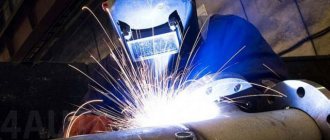
- Electric welding. Its popularity is ensured by its simplicity and low cost of work. You can often hear the name “arc” or “contact”. It takes longer to form a seam than with other types. However, these disadvantages are offset by the versatility and functionality of the method.
- Cold. It is carried out due to the deformation of the material that occurs when exposed to pressure. With this type of welding, the connection is made through the diffusion of atoms. There are cases when other types are not able to provide a seam, for example when welding parts made of copper and aluminum.
- Gas. It is produced using a gas torch that can heat the objects being welded to a high temperature. The advantages of this technology include low complexity of work, smooth, neat seams, as well as good productivity. The disadvantages include the considerable cost of the method, because expensive resources are consumed in the process.
Methods for forming seams can also be divided according to two criteria:
- hot or cold;
- manual or automatic;
With the manual welding method, work at all stages is carried out by a person, with the automatic method - with the help of machines; human participation is required only at the stage of preparing and setting up the welding equipment.