Types of centrifugal pumps
Single stage
The simplest option, horizontal and vertical execution.
Multistage
The performance is higher than that of a single stage. Several impellers pump a larger volume of liquid per unit time.
Semi-submersible
Vertical version only, the lower part of the body is placed in the liquid.
Submersible
Completely sealed housing, can operate completely immersed in various liquid media.
Double sided
The difference between the model is that the discharge and suction elements are located on the same axis.
Increased tightness
The pump is designed to operate in chemically aggressive liquid media.
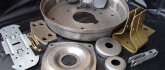
Main components of a centrifugal pump
The general design of the device for all centrifugal pumps is similar - it is a casing and an impeller with blades. When the blades rotate at a certain speed, they create a centrifugal effect, the pressure increases and, as a result, the liquid moves from the inlet to the outlet valve.
- 1. Oil seal box cover
- 2. Body
- 3. Impeller
- 4. Lining plate
- 5. Cover
Shaft connection type
There are 2 ways to transfer rotation from the motor to the pump: through a coupling or directly .
If the pump and motor are two separate machines, then they must be connected by a coupling.
Coupling connection
Couplings come in different shapes, sizes and designs. And one common requirement for them is to ensure the correct integrity of the shafts, otherwise without them, ensuring integrity would be a very sophisticated process.
To facilitate and maintain integrity, the engine and pump are mounted on a common support - a base plate.
Or, in the case of vertical installations, the engine is located on the frame.
This type of connection between the motor and the pump is called coupling. For large powerful installations and pumps with a dismountable casing, connection via a coupling is the only possible option.
The second connection method is direct. The engine and pump are located on a common shaft with a wheel located in a cantilever on the other side of the engine shaft. In this case, the installation does not require a coupling or complex procedures to maintain integrity.
However, because the motor and pump are located on the same shaft, supported only by the motor bearings, this method is only suitable for small and medium-sized end suction pumps.
Additional centrifugal pump components
Depending on the design of the pump and the type of pumped liquid, the basic version of the centrifugal pump can be supplemented with various devices.
Inlet check valve
Protects the housing from flooding when the system is activated.
Inlet grid
Acts as a mechanical coarse filter, protecting the pump mechanism from solid particles.
Gate valve
Blocks the flow of liquid to the pump inlet.
Safety valve
Protects the system from water hammer.
Vacuum gauge
Placed between the valve and the pump, it measures the air vacuum. If there is excess air in the system, it should be removed. A valve located on the pipeline is designed to bleed off excess air.
Pressure gauge
Measures the pressure generated by the pump. Installed on the pressure pipe.
Working wheel
There are 3 types of impellers:
- open,
- semi-closed
- closed
The simplest design is the open wheel, which consists of razor-sharp blades evenly spaced on a hub.
Open wheel
The large, unrestricted fluid supply allows this type of wheel to transport fluids containing dirt, dust, sediment, and solids , making them ideal for waste pumps.
It is used in water treatment plants where wastewater is pumped to treat coarse sludge with solid impurities. Therefore, it has cutting blades at the front of the wheel to cut very large impurities.
If the blades are placed on the back plate, then such a wheel is called semi-closed .
Semi-closed wheel
If the blades are between two plates, then it is called closed .
Closed wheel
Closed wheels are more efficient than semi-closed and open wheels. Because the fluid flow follows a strictly defined path. This means that more fluid comes out of the pump and less simply circulates inside the wheel.
Their disadvantage is that they can easily become contaminated with debris.
A very popular misconception is that swirling blades help push fluid. But that's not really what they're designed for.
The purpose of the blades is to guide the liquid along the smoothest path. Backward-twisted blades help stabilize fluid flow conditions at high speeds and reduce engine load.
By the way, read this article too: Peristaltic (hose) pump operating principle
The correct direction of rotation for this wheel is counterclockwise . Therefore, by the direction of the bends of the blades, we can tell the direction of movement of the wheel.
How does a centrifugal pump work?
The task of a centrifugal pump is to create fluid pressure to move it through a pipeline. Pressure in a liquid medium appears due to the centrifugal effect from the rotation of the impeller with blades. The blades reject the liquid, imparting kinetic energy to it. The configuration of the internal volume is such that the resulting pressure directs the liquid to the outlet of the pump.
centrifugal pump operation diagram
The wheel with blades is fixed coaxially on the working shaft. The shaft is connected to an electric motor using a magnetic coupling. The liquid enters the pump through the suction pipe. Some models have several impellers, which significantly increases their productivity. The method is universal, suitable for pumping not only water, but also other liquids. The main condition is that for effective pumping the working volume of the pump must be completely filled with liquid. Otherwise, the operation is idle and the liquid medium does not move.
Circulation pump device
In order to efficiently transport any liquid and saturate it with kinetic energy in the process, the equipment has been specially developed by specialists over many years. The unit has two main elements:
- A rotating disk that is equipped with curved blades is what experts call an impeller.
- The pipe is of a special design; it has a unique shape and is called a spiral casing. It is in this part that the wheel and liquid for transportation are located.
Pump housing
The part has the shape of a spiral, which gradually changes in radius; to give a clear example, the element is somewhat similar to a snail shell. The cavity located inside each zone has a certain permeability.
Before exiting, the liquid passes through a specially designed cutwater, which looks like a protruding metal wedge.
Working wheel
Experts distinguish only three types of element, which look like this:
- Open.
- Closed.
- Semi-closed.
The first design option is the simplest, the blades are similar to ordinary open-shaped blades, they are sequentially located on a metal sleeve, often the design is monolithic. The element is ideal for equipping garbage pumps, where during operation the liquid is dirty, dusty, with solid particles and impurities.
A semi-closed wheel can be recognized by the location of the blades; they will be located on the back plate. The design option, where the elements are located between two plates, is considered a closed type.
Shaft and bearings
To ensure the operation of any type of wheel, you will need a rotating shaft, which must be properly secured in the housing of a Grundfos or other brand of circulation pump.
There are only two types of element:
- Cantilevered.
- Symmetric.
Each type of arrangement provides for the presence of bearings, which in each embodiment will be on one or two sides.
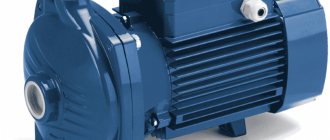
Advantages of the centrifugal pumping method
Centrifugal pumps are compact, which allows them to be placed in a small volume. Compactness implies low weight, which can be very important in some industries and individual products. The simple design makes the pump reliable, capable of operating for a long time, and directly determines the low price of the product.
horizontal single stage cantilever pump
Among the advantages, easy installation should be mentioned. Water from the centrifugal pump is supplied to the water supply system smoothly, without water hammer. The rotation speed of the impeller is easily adjustable. There are models capable of pumping aggressive liquids and liquids with large amounts of impurities.
Mounting design
The performance and ability to process large quantities of liquid will depend on this indicator. There are only two types of arrangement of the main elements in the housing of a centrifugal pump. To understand all the nuances, it is worth considering them separately.
Cantilever fastening
This design option involves bearings on one side and an impeller on the other. The suction and pressure openings are located perpendicularly; often designs of this type have an end element for suction, which is installed at 90 degrees.
The design has a zone where the pressure increases to a maximum, after which the liquid with the resulting energy penetrates the casing of the spiral sample. Axial force occurs when the pressure balance is destroyed at the moment when water reaches the back plate and the half-open wheel.
Symmetrical mounting
Quite a good mount. The shaft is on bearings on both sides, it becomes possible to install wheels with double suction.
Due to the pressure balance, the load is evenly distributed over the pump body, which creates high reliability.
Maintenance of the unit is also easier; to carry out the work, the technician only needs to unscrew two bolts and remove the cover in order to understand the cause of the breakdown or remove the blockage.
Professional mechanics call pumps with a symmetrical arrangement a collapsible casing, this is due to the ease of dismantling without the need to remove the entire system.
Industrial use of centrifugal pumps
Pumps are used so widely in industry and other applications that it is difficult to name industries that do not use them. Of course, in general, the high performance, reliability and compactness of centrifugal devices are especially in demand in the oil, chemical and similar industries. Wherever large volumes of liquid media need to be constantly and quickly moved. In addition to conventional pumps, such pumps successfully pump acids, heavy and dense fractions at oil refineries.
centrifugal pump in a heating system
Able to work for a long time in systems at high pressure and temperature. For example, they create a constant circulation of coolant in the heating circuit. The high resistance of centrifugal pumps to pollution levels makes them indispensable when pumping silted wells, other water sources with a high level of solid particle pollution, when draining flooded rooms, etc.
Pump flow elements
The operating principles of the flow path elements are common to most centrifugal pumps. Flow path elements are parts that are in contact with liquid. The elements of the flow part of a single-stage in-line pump are shown in Figure 1.2. The following sections describe the elements from the inlet to the outlet flange.
Inlet flange and inlet
The pump is connected to the pipeline using inlet and outlet flanges. The flange design depends on the pump application. Some types of pumps do not have an inlet flange because the inlet is not connected to a pipe but is immersed directly in the liquid.
The liquid from the inlet is directed to the impeller inlet. The design of the inlet depends on the type of pump. The four most common inlet types are in-line, single-suction, double-suction and submersible pump inlet, see Figure 1.3.
In-line pumps are designed for installation on straight sections of pipes, which is where they get their name. The inlet channel directs fluid to the impeller inlet.
End-suction pumps have a very short, straight inlet because the impeller inlet is located in close proximity to the inlet flange.
Double suction pump impellers have two impeller inputs. The incoming flow is split and fluid is supplied from the inlet flange to both impeller inlets. This design minimizes axial force, see section 1.2.5.
In submersible pumps, the electric motor is often located below the flow path, and the inlet is located in the middle of the pump, see Figure 1.3. This design eliminates hydraulic losses associated with the movement of fluid along the electric motor. In addition, the electric motor is cooled by immersion in liquid.
The supply channel must create a uniform speed profile at the impeller inlet, as this ensures the best pump performance. Figure 1.4 shows an example of the velocity distribution in various sections of the supply channel.
Working wheel
The rotating impeller blades transfer energy to the fluid by increasing its pressure and speed. Fluid is drawn through the impeller inlet and moves through the impeller channels formed by the blades between the front and rear discs, see Figure 1.5.
Impeller design is determined by pressure, flow and application requirements. The impeller is the most important part that determines the performance of the pump. Pump variations are often created only by modifying the impellers.
The ability of the impeller to increase pressure and create fluid movement mainly depends on whether the fluid in the impeller is moving in a radial or axial direction, see Figure 1.6.
In radial impellers, there is a significant difference between the diameters at the inlet and outlet of the impeller, as well as between the diameter of the impeller and the outlet width (channel height) at the outlet of the impeller. This impeller design is used to create high pressure at low flow. Conversely, relatively low pressure and high flow are created in axial impellers, while the direction of movement does not change and the outlet width is larger. Radial-axial wheels are used when a compromise between pressure increase and flow is required.
The impeller has several blades. The number of blades depends on the required performance and noise limits, as well as the number and size of solid particles in the liquid. Impellers with 5-10 channels provide maximum efficiency and are used for liquids that do not contain solids. For liquids containing solids, such as wastewater, impellers with one, two or three channels are used. The leading edge of the blades of such wheels has a special profile to reduce the risk of wheel blocking by solid particles. Impellers with one, two or three channels can pass particles of a certain size. A pump with a single-channel impeller is shown in Figure 1.7.
Impellers without a front disc are called open impellers. Open impellers are used if the wheel needs to be cleaned or there is a risk of wheel blocking. Vortex pumps with open impellers are used to pump wastewater. In pumps of this type, the impeller creates a fluid flow that resembles the shape of a tornado vortex funnel, see Figure 1.8. Vortex pumps have low efficiency compared to pumps equipped with disc impellers and seals between the impellers and the pump body. Once the type of impeller has been selected, impeller design is a trade-off between frictional losses and losses due to uneven speed profiles. In general, a uniform velocity profile is achieved by increasing the length of the impeller blades, but this results in increased friction.
Coupling connection and drive
An electric motor is usually used to drive the impeller. The connection between the electric motor and the impeller is a weak point due to the difficulty of sealing the rotating shaft. In this regard, two types of pumps are distinguished: pumps with a dry rotor and pumps with a wet rotor. The advantage of dry rotor pumps compared to wet rotor pumps is the ability to use standard electric motors for drive. The disadvantage is the seal between the motor and the impeller.
In glanded rotor pumps, the electric motor and liquid are separated by a shaft seal; long shaft or magnetic coupling designs are also used. In a pump with a shaft seal, the fluid and the electric motor are separated by O-rings, see Figure 1.9. Mechanical shaft seals require no maintenance and leak less than packing seals. The service life of mechanical seals depends on the fluid, pressure and temperature.
If the electric motor and the liquid are separated by a long shaft, then the parts of the pump unit do not contact each other and the shaft seal can be eliminated, see Figure 1.10. This scheme has installation limitations, since the electric motor must be placed above the flow path and the surface of the liquid in the system. In addition, the efficiency of the pump is reduced due to leaks through leaks between the shaft and the pump housing, as well as as a result of friction between the liquid and the long shaft.
In pumps with magnetic couplings, the electric motor and fluid are separated by a rotor shell made of non-magnetic material, which eliminates problems with the sealing of the rotating shaft. These types of pumps have magnets attached to the impeller shaft, called internal magnets. The electric motor shaft ends in a cavity, on the inner surface of which external magnets are fixed, see Figure 1.11. The rotor bowl is fixed in the pump housing between the impeller shaft and the cavity. Torque from the electric motor shaft to the impeller shaft is transmitted using magnets. The main advantage of this design is the tight seal of the pump, but this type of coupling is expensive. Therefore, this type of seal is used only when it is necessary to ensure complete tightness of the pump.
In canister pumps, the rotor and impeller are separated from the motor stator. As shown in Figure 1.12, the rotor is bathed in fluid, which lubricates the bearings and cools the motor. Fluid around the rotor causes friction between the rotor and the separating bowl, which reduces pump efficiency.
Impeller seal
When the pump operates, fluid flows through the gap between the rotating impeller and the stationary pump casing. The value of cross-flow depends mainly on the design of the gap and the pressure drop across the impeller. The fluid then returns to the impeller inlet, see Figure 1.13. Thus, the impeller pumps not only the liquid entering the pump inlet, but also the overflow. To reduce cross-flow, an impeller seal is installed.
There are various designs and material combinations of impeller seals. The seal is usually pressed directly into the pump housing or installed as additional rings. It is also possible to use shaft seals with floating seal rings. In addition, there are a number of rubber ring seals that are best suited for fluids containing highly abrasive contaminants, such as sand.
Achieving the optimal balance between flow and friction is the most important task when designing impeller seals. A small gap limits flow but increases friction and the risk of snagging and noise. Small clearance also increases the requirements for precision processing and assembly, which increases production costs. Pump type and size must be considered to achieve the optimal balance between flow and friction.
Cavities and axial bearing
The volume of the cavities depends on the design of the impeller and pump housing, they determine the flow around the circumference of the impeller and the ability of the pump to operate in the presence of sand and air in the liquid.
The rotation of the impeller creates two types of flows in the cavities: primary and secondary. Primary flows are vortices rotating together with the impeller in cavities located above and below the impeller, see Figure 1.14. Secondary flows are much weaker than primary flows.
The nature of the movement of the primary and secondary flows affects the pressure distribution on the outer side of the front and rear impeller disks, which leads to the occurrence of axial force. The axial load is the sum of all the forces acting in the axial direction and resulting from the pressure difference in different parts of the pump. The main force arises from the increase in pressure when the impeller rotates. The entrance to the impeller is under inlet pressure, while the outer surfaces of the rear and front disc are under outlet pressure, see Figure 1.15. One end of the shaft is under atmospheric pressure, while the other end of the shaft is subject to system pressure. The pressure increases radially from the center to the circumference of the wheel.
The axial load is absorbed by the axial bearings, so they are acted upon by the forces applied to the impeller.
If complete compensation of the axial load in the axial bearing is not possible, the axial forces acting on the impeller must be balanced. There are several possibilities to reduce the axial load on the pump shaft and thus reduce the load on the axial bearing. All methods of reducing axial load lead to hydraulic losses.
One solution to balance the axial forces is to install small holes in the rear disc, see Figure 1.16. The flow through the holes affects the flow in the cavities above the impeller, this leads to a decrease in the axial force, but increases the flow.
Another way to reduce axial load is to combine relief holes and an impeller seal on the rear disc, see Figure 1.17. This reduces the pressure in the cavity between the shaft and the impeller seal and promotes better pressure balancing. The impeller seal creates additional friction but reduces flow through the relief ports compared to a design without a seal.
A third way to balance axial forces is to install vanes on the rear side of the impeller, see Figure 1.18. Similar to the two schemes described above, in this case the flow rate on the rear disk decreases, as a result of which the pressure on the disk changes proportionally. However, additional vanes consume a certain amount of energy without increasing pump performance. Therefore, this design reduces efficiency.
The fourth method of balancing the axial load is to place fins in the cavity of the pump housing under the impeller, see Figure 1.19. In this case, the speed of the primary flow in the cavity under the impeller decreases and, accordingly, the pressure on the front disk increases. This balancing method increases friction on the disk and flow losses due to increased pressure.
Spiral chamber, diffuser and outlet flange
The spiral chamber (volute) is designed to collect liquid from the impeller and direct it to the outlet flange. In the volute chamber, the dynamic pressure in the impeller is converted into static pressure. The speed gradually decreases as the cross-section of the fluid flow increases. This transformation is called flow deceleration. An example of flow deceleration is a decrease in flow velocity as the cross-section of a pipe increases, see Figure 1.20.
The volute chamber consists of three main elements: an annular diffuser, a volute and an outlet diffuser, see Figure 1.21. The conversion of energy from speed to pressure occurs in each of the three elements.
The primary annular diffuser is designed to direct fluid from the impeller to the volute. The cross-sectional area of the annular diffuser increases as the diameter increases from the impeller to the volute. To enhance flow inhibition, blades can be installed in the annular diffuser.
The main purpose of the volute is to collect liquid from the annular diffuser and direct it to the outlet diffuser. To create uniform pressure within the cochlea, the cross-sectional area of the cochlea must increase as it moves from the protrusion to the neck of the cochlea. The throat is the area behind the protrusion where the cross-sectional area of the outlet diffuser is smallest. The flow conditions in the volute can only be optimal in the design mode. In other modes, radial forces appear that act on the impeller due to pressure changes around the circumference of the volute. Radial forces, like axial ones, must be absorbed by the bearing, see Figure 1.21.
The outlet diffuser connects the neck to the outlet flange. The cross-section of the diffuser gradually increases from the neck to the outlet flange, which leads to an increase in static pressure.
The volute chamber is designed to convert dynamic pressure into static pressure with minimal pressure loss. The greatest efficiency is achieved with the correct balance between the change in speed and the friction of the fluid against the inner surface of the volute. When designing a volute chamber, attention must be paid to the following parameters: volute diameter, volute cross-section geometry, protrusion shape, area and radial position of the throat, as well as the length, width and curvature of the diffuser.
Guide vane and outer casing of the pump
To increase the pressure at the pump outlet, it is possible to connect several impellers in series. A guide vane is used to supply fluid from one wheel to the next, see Figure 1.22. The impeller and guide vane are collectively called the stage or chamber. Several connected chambers of a multistage pump are called a chamber set.
In addition to transferring fluid flow from one impeller to the other, the guide vane performs the same basic function as a volute: converting dynamic pressure into static pressure. The guide vane reduces the speed of unwanted circular movement of the fluid, since such movement negatively affects the efficiency of the next impeller. The speed of the circular movement of the liquid is regulated by the guide vanes of the apparatus.
In in-line multistage pumps, fluid moves from the top of the chamber set to the outlet in a channel formed by the outer part of the chamber set and the outer pump casing, see Figure 1.22.
When designing a guide vane, the same factors should be taken into account as when calculating impellers and volutes. In contrast to the volute chamber, the guide vane does not create radial forces on the impeller, since it is axisymmetric.
Centrifugal pump operation
Despite the high resistance to high concentrations of contaminants in the liquid, when using centrifugal pumps it is necessary to follow some rules:
- equip the pump with measuring and control equipment that will report on the condition of the equipment
- there should be a mesh at the inlet to protect the impeller blades from large solid fragments
- for optimal operating mode, the pump performance must correspond to the volume of pumped liquid, including at peak moments of increased loads
- the materials of the pump parts must match the type of liquid being pumped, this is especially important when choosing the type of seals
- The pump motor must be protected from possible power supply problems by additional equipment
- a circuit breaker is required to turn off the pump if the motor or impeller jams