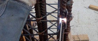
Manual arc welding of pipes remains one of the most common methods of installing pipeline systems, which are both independent transport and distribution networks and components of process equipment. High quality joints of pipeline systems is the key to their safe operation.
Welding methods, types of joints, geometric parameters and standard dimensions, as well as methods of cutting edges - all this is regulated in GOST 16037-80 manual arc welding of welded joints. Strict adherence to the requirements of the standard in the design, formation of the technological process and welding of steel pipelines ensures the required level of quality.
Connection symbols
The standard describes three types of pipeline welded joints:
- butt, designated by the letter C
- corner, letter U
- overlap, designated by the letter N.
Within each type, the current standard details many subtypes depending on:
- type of weld;
- number of welding sides;
- lining configurations;
- its removability;
- without bevel, with bevel of one or two edges;
- edge section shapes
- suture material cross-sectional shapes
- welding method;
- wall thickness;
- pipe diameter.
Example of type C13 designation.
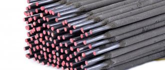
The symbol, in addition to the type, includes a sign of closed line, welding method, leg parameters and auxiliary symbols . In accordance with GOST 16037 80, argon, submerged arc and gas welding is used. Work in an atmosphere of protective gases can be performed with either a fusible or non-fusible electrode. Typically pipes are made of carbon steel. Stainless alloys are used for work in aggressive environments. Alloys of non-ferrous metals are used less frequently.
Main types of connections
Pipe joining methods can be divided into two categories.
- Detachable - when the joint is fixed using a thread, socket or special fitting (pipe connector), which, if necessary, can be removed to open the pipeline, repair it or replace a section of pipe.
- One-piece - with a permanent fixation of the joint, to open which you will need to cut the pipe.
In household systems, detachable connections are more often used. They are convenient, practical, and allow you to independently install and repair pipelines without complex equipment. For such connections there is a limitation on the pipe diameter:
- 315 mm for flexible pipes;
- 600 mm for rigid pipes.
For pumping gas, chemically aggressive media, as well as when laying long pipelines, preference is given to permanent connections.
Installation of a gas pipeline distribution system Source pravdaurfo.ru
Structural elements and dimensions of workpiece edges and seams
Pipe welding GOST 16037-80 implies the following basic elements:
- s: workpiece thickness;
- b: distance between the edges of the workpieces;
- e: seam width;
- g: its convexity;
- a is the total thickness of the seam;
- c - blunting of the edge;
- B – depth of overlap;
- K—leg of fillet weld;
- Dn – overall pipe diameter;
- f – flange chamfer size.
For a number of seams, only some of the specified parameters are relevant. Dimensions are given in the standard depending on the pipe welding method regulated by GOST.
Video description
The process of welding pipes with electrodes is described and shown in the video:
Polymer pipes are welded with a special soldering iron, with which the plastic is heated immediately along the entire circumference of the pipe. After joining the parts, the molten material adheres and, upon cooling, forms a reliable hermetic connection.
This method does not involve butt welding. Installation is carried out using couplings, angles and other connecting fittings, the inner diameter of which coincides with the outer diameter of the pipes. This is how most cold and hot water supply systems are installed, as well as heating systems in private houses and apartments.
Types of Welds
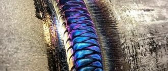
Butt welds are used when welding circumferential joints of pipes in accordance with GOST. Such compounds are designated C1-C53
They are made single- and double-sided, with straight and rounded beveled edges and with boring.
Single-sided seams may have a removable or retained backing, as well as a fusible insert.
Sector connections at pipeline turns are made with beveled edges and are designated C54-C55.
Flange and pipe connections are designated as C56
An example of the designation of a U2 type corner connection.
Fillet welds are designated U5-U21, lap welds H1-H4
How to connect pipes from different materials?
In some cases, it is necessary to connect products that are not homogeneous in material. There are special options for these purposes.
How to connect a polypropylene (plastic) pipe to a metal one?
Many people ask the question: how to connect polypropylene pipes with metal ones? There are several popular methods for this:
- thread;
- flange pipe connection.
In the first case, the coupling of pipes of heterogeneous material is carried out using couplings. One end of such a coupling is equipped with a thread, and the other has a smooth surface for joining with polypropylene.
The flange method involves the use of flanges. This connection is made using studs and bolts.
Note! Flanges are used in structures that are often disassembled during operation.
How to connect metal-plastic pipes with metal ones?
The most popular options in this case are:
- press fittings;
- compression fittings.
In the first case, the connection between pipes of heterogeneous material can be made in two ways:
- sliding press fitting;
- crimp coupling.
It is important to remember that connecting metal-plastic pipes with metal and other pipes of heterogeneous material is quite a responsible undertaking and should be carried out by specially trained specialists. Incorrect installation of the connecting element will lead to an emergency in the pipeline.
Cutting pipes for welding
GOST regulates the types and characteristics of preparation for welding work for various types of joints:
- butt;
- corner;
- overlap
Before starting welding work, preparation must be carried out. It includes:
- mechanical cleaning is performed to remove dust, traces of corrosion, and oxide film;
- chemical treatment to remove oil and fat stains and oxide film;
- cutting edges.
Cutting is carried out using mechanical edge processing . When installing pipelines, it is performed by special machines. During repair work, cutting using angle grinders is allowed.
Edge cutting is carried out with a workpiece thickness of 4 mm or more.
For corner connections for bends, one or both edges are beveled at an angle of 45°.
Joints on pipelines are divided into rotary and non-rotary.
Welding steel pipelines GOST 16037 recommends using rotary joints whenever possible. They are welded in the most convenient and advantageous lower welding position; the cutting of the edges for it is carried out equally along the entire perimeter of the joint.
A fixed joint has to be welded in all welding positions, changing from one to another as you move along the seam around the pipe.
The difference between the wall thicknesses of butt-joined pipes should not be more than 10% and not exceed three millimeters. In this case, the width of the gap should be constant throughout the entire joint and range from 2 to 3 mm.
Before starting installation, it is necessary to treat the edges and heat-affected area by 20-30 mm, clearing it of mechanical impurities, traces of corrosion and oil and fat stains.
Before the main electric arc welding, the ends of the pipes are clamped to each other:
- pipes up to 300 mm in diameter: 4 tacks;
- over 300 mm - evenly every 200-300 mm.
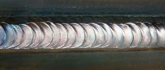
Pipes with a wall thickness of 12 mm or more are boiled in three stages. At the first stage, the root of the seam is formed in the form of a roller with an elevation of 1.5-3 mm, evenly distributed along the length of the joint. In this case, the electrode should be moved back and forth.
Features of connecting profile pipes
Profile pipes have good strength and relatively low weight, so they are often used for the installation of frame structures, as well as for other construction purposes.
The shape of profile pipes can be:
- rectangular (the most common shape);
- square;
- ovoid (oval);
- others (more complex forms).
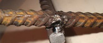
The most reliable way to create structures from profile pipes is to fasten them by welding
Electric arc welding is usually used to connect square pipes. There are also special connections that are made using bolts and rivets. Square and rectangular pipes are joined using the same methods.
In addition, various parts can be joined to such pipes. This joining is carried out using self-tapping screws. These elements do not require preliminary holes.
Welding chamfers
When joining thick pipe blanks, the formed seam should be made thicker than the part itself . To form a connection with the specified geometric parameters, it is necessary to cut the edges by chamfering. After this, the electrode will be provided with access for high-quality welding of the seam to the full depth.
The main chamfer parameters are:
- Gap b. the distance between the workpieces is up to 2-3 mm.
- Blunt C. The part of the edge that is not beveled. it is left in place to reduce the likelihood of burning through the root of the seam..
- Bevel angle β. With double-sided cutting, the acute angle takes values of 15-30°, with one-sided cutting, up to 45°.
- Cutting angle α. An obtuse angle is equal to twice the bevel angle and provides proper access to the root of the weld for welding equipment.
Chamfer options.
If the dullness value is small or non-existent, then burn-through is prevented by such methods as:
- the use of linings that prevent the flow of molten metal;
- flux pad welding;
- pre-cooking;
- execution of the lock.
Technologists should pay special attention to the correct calculation and compliance with the optimal cutting parameters . This allows you to reduce labor intensity, use materials sparingly and maintain cost control.
When preparing butt joints, the type of chamfer depends on the thickness of the parts:
- 3-25mm: one-sided chamfer;
- 26-60mm: double-sided;
The following boundaries are set for corners:
- 3-20mm: one-sided;
- 21-50 mm: double-sided.
Based on the geometric shape of the cross-sectional profile, the following types of cutting are distinguished:
- regular bevel, profile is a trapezoid,
- X-shaped, two bevels are made towards each other in such a way that the cross-sectional profile of the double-sided cut visually resembles the outline of the letter X;
- U-shaped, the cross-sectional profile is curvilinear and resembles the outline of the letter U.
GOST for pipe welding recommends using a U-shaped groove for large workpiece thicknesses , in order to reduce the cross-sectional area of the seam and, therefore, reduce material consumption and increase work speed.
The cutting shape is chosen based on the thickness of the pipes:
- 3-25mm: X-shaped or V-shaped;
- 26-60mm - U-shaped;
- more than 60 mm - special forms.
They are:
- ledges;
- complex curvilinear profiles designed to maintain access of the electrode to the root of the seam and reduce the cross-sectional area.
The following methods are used for cutting:
- Gas cutting . Characterized by low accuracy and insufficient surface quality. Requires additional processing by mechanical means.
- Machining . Planing or milling gives sufficient surface cleanliness and shape. Slotting also requires finishing machining.
When cutting the edges of large diameter pipes, special trimming machines are used. During repair work on heating lines, cutting is often done manually using grinders.
Video description
One of the methods for assembling profile pipes with bolts is shown in this video:
When increased strength is not required from the structure, it is assembled using fittings made of hard plastic. they come in the form of couplings, tees, angles, crosses, and are inserted into the ends of the pipes at their joints.
Plastic connectors for corrugated pipes Source odstroy.ru
The elements of the crab system are overhead metal parts with which the structure is fixed using bolted connections. They can also connect pipes along their length, form branches, crosshairs at right angles. The strength of such a connection is not inferior to a welded one.
Crab system - tee Source stpulscen.ru
Welding the flange to the pipe
Before welding work, edge preparation is carried out. The seams are cleaned until shiny. When independently assembling metering units or inserting shut-off valves, it is important to take into account the thickness of the sealing gasket; the disc is installed taking into account the thickness of the rubber. The bolt heads on the flanges are located on one side only. The ends protrude at least 3 threads. The disk mirror is always located above the seam and edge; the edge of the rolled product should not extend beyond the plane of the disk. Tack joints help to weld the flange to the pipe evenly; when the disk is immobilized, you can start making seams.
At a pressure of up to 10 MPa, welding is carried out without a bevel; at a high pressure, up to 25 MPa, welding is carried out with bevels.
Rotators are used to weld flanges to steel pipelines. They give the unit mobility, improve access to the working area, and facilitate the welding process. During the welding process, the electrode remains stationary, the assembly gradually rotates around its axis. The rotator is used to finish cleaning the seams, priming and painting the flange assembly.
Important points when assembling a flange connection:
- it is necessary to fasten the disk perpendicular to the pipeline, a control triangle and a probe are used for checking, the permissible deviation is 2% of the outer diameter;
- the axes of the bolt holes on the two disks must coincide; alignment is checked with a level and plumb line. Permissible deviations: a) 1 mm for holes with a diameter of 18 to 25 mm; b) 2 mm for diameters up to 41 mm.
The permissible disc deviation is 2% of the outer diameter.
The “boat” technique is used for connections without backlash; the edges are welded to a greater depth. If the gap is within 1.5 mm, welding is performed with transverse oscillatory movements, the electrode is held at an angle of 30° to the surface of the pipe. A backlash of 4–5 mm is formed using a fillet seam with large stitches (cathetes). If the gap is large, two penetrations are allowed.