January 17, 2018
power managementautomationcritical applicationslab instrumentsInfineonarticlediscrete semiconductorsIGBT
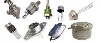
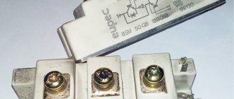
Until now, in many industries there is no alternative to the application of protective and decorative coatings through galvanization . But the 21st century places new demands on flexibility and environmental friendliness of production, which is why the requirements for equipment that controls the electrical parameters of electroplating have increased. Fortunately, at the same time, an element base appeared that meets new requirements, in particular, Infineon IGBT modules .
Already at the dawn of the development of electroplating, a problem arose due to the fact that the coating process required direct current, while alternating current networks were being developed everywhere. At first, electroplating installations were powered by galvanic cells. Then, with the invention of mercury rectifiers at the beginning of the 20th century, it became possible to apply coatings by receiving energy from an alternating current network. Since then, the equipment that provides the specified power supply parameters for the galvanic bath is called a “rectifier” among electroplating specialists. Although now this is a much more complex device, which includes not only a voltage converter and, in fact, a rectifier, but also a stabilizer and some other components that provide additional functions (for example, timers). From the point of view of electrical engineering, such systems are correctly called “power supplies”. However, in this article we will use an already established term.
Each type of galvanic process and each coating material has its own electrical parameters. In some cases it is necessary to stabilize the voltage, in others it is necessary to stabilize the current density (the ratio of the current strength to the surface area of the product being coated).
The ability to adjust parameters in rectifiers based on semiconductor diodes was realized by switching taps from the transformer winding. At the same time, to ensure high quality coating, an additional voltage stabilizer was required at the input of the rectifier (ferroresonant, relay, electromechanical). More advanced thyristor rectifiers, which replaced diode rectifiers in the 60s of the 20th century, made it possible to smoothly adjust the parameters. It became possible to combine a rectifier and stabilizer in a single device. However, until the 2000s, it was common practice to supply industrial plants with rectifiers specifically designed for a specific galvanic process.
The global economic crisis of 2008 led to the fact that companies involved in electroplating began to incur losses. A solution was found in the creation of flexible production facilities that can adapt to the needs of a wide variety of customers [1]. As a result, rectifiers whose parameters can be quickly changed have become in demand in electroplating production.
At the time of writing, in Russia there was also an increase in interest in rectifiers for electroplating based on IGBT transistors, which is due to the policy of import substitution, as well as the desire of domestic enterprises to increase exports, which requires improving the quality and reducing the energy intensity of products.
A simple electroplating power source from a computer power supply
The article discusses the design of a power source designed for use in electroplating. It is made on the basis of an ATX computer power supply and allows you to supply a stabilized current of up to 20A to the load for a time set using a timer.
The topic of amateur electroplating is quite popular. Electroplating technology requires a stable current source of fairly high quality. The use of medium-power amateur radio laboratory power supplies is not always acceptable for this purpose, since they usually try to balance the characteristics in such a way as to obtain a large output voltage range at a small current. On the other hand, all kinds of chargers for lead-acid batteries allow you to obtain a high current, often stabilized, but have poor output voltage quality, which does not allow you to obtain a smooth metal coating of the product.
Thus, the author decided to produce a specialized power source for use in electroplating (IG), which has the following main technical characteristics:
- mains supply voltage
230V;
- two interconnected channels with a continuously adjustable stabilized DC output voltage: in the first channel - from 0 to 20 V at a current of up to 10 A;
- in the second channel - from 0 to 8 V at a current of up to 20 A;
A lot of articles have been written about the modification of computer power supplies (BPSU), including by the author. A feature of this design is the use of a 5-volt output of the BPPK to obtain a large output current, a modified control and indication circuit, and the ability to connect a shutdown timer.
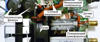
Description of the device circuit
The electrical circuit diagram of the IPG is shown in the figure. The IPG was based on a 300 W ATX power supply with a temperature sensor to control the rotation speed of the cooling fan. The original BPPK used a PWM controller of the DR-B2005 type, so an additional control board on the TL494 (DA3) controller was used to remake it. More information about such a replacement of a PWM controller can be read in the article “Converting computer power supplies with PWM controllers such as DR-B2002, DR-B2003, SG6105 into laboratory power supplies.” The control circuit is similar to that described in the article “Bipolar power supply - charger from a computer power supply.” To provide indication of the transition of the IPG to the current limiting mode, according to the recommendations given in the article by V. Andryushkevich “Converting a computer power supply into a laboratory and charger” (Radio - 2012, No. 3), a comparator DA2 was added to the control circuit, the output of which is loaded by LED HL2.
The circuit of the control circuit power supply module based on transformer T1 of the “standby” mode of the BPPK is similar to that described in the article “Conversion of computer power supplies with PWM controllers such as DR-B2002, DR-B2003, SG6105 into laboratory power supplies.” The original BPPK had a temperature sensor and the author decided to leave it, since automatic adjustment of the cooling fan speed significantly reduces noise. Therefore, an integrated stabilizer DA1 was added to the power supply circuit of the M1 fan, which supplies a stabilized voltage = 12 V to the thermostat.
The power supply module has two channels, since the 12-volt and 5-volt outputs of the T2 power transformer with the corresponding rectifiers are used. Using a 5-volt output allows you to get more current when needed than using a 12-volt output. The rectification and filtering circuits for both channels have no special features and correspond to the standard BPPK circuit. The current sensor Rш1 is connected to the common wire break, so it does not matter which channel is loaded, the current limitation will work in any case.
To indicate the level of output voltage and current, a widely used small-sized digital multimeter of the DT830V type was used, from which all standard dividers were removed, and the input circuit R6, R8, C7 was assembled, a decoupling capacitor C8, a shunt Rsh2 and an additional resistance R5 were installed. Measurements are made at a limit of 20V, which allows you to display the voltage and current value with two decimal places, that is, from 0.00 to 19.99. Using switch SA1, the voltage measurement channel is selected, and switch SA3 selects the type of work. The multimeter is powered by a separate stabilizer based on elements T3, VD5, VD10, C3, which is not galvanically connected to the rest of the circuit elements.
The IPG shutdown timer is based on the popular Chinese electronic-mechanical clock with an alarm clock. The clock is powered from the standby power supply BPPK through contact K1.1 of relay K1. The power circuit is a parametric stabilizer based on elements R4, HL1 with a stabilization voltage of about 2 V. Then this voltage is normalized to the nominal (about 1.5 V) using diode VD11 and filtered by capacitor C6. The capacitance of the capacitor is selected in such a way that the VD11 LED blinks while the clock is running, thus indicating its progress. Contact SA2 of the clock, which turns on the alarm signal, when closed, energizes relay K1, contact K1.1 opens, turning off the power to the control circuit and clock. Thus, the key transistors are not controlled and the voltage from the IPG output is removed.
Design, details and adjustment of IP
All elements of the IPG, except for the clock, are located in the BPPK case, in one of the sides of which a large hole is cut to accommodate the front panel with controls and indications. The clock is connected to the main unit through a connector located on the back wall of the IPG using a cable.
The individual functional blocks of the design are assembled either on separate printed circuit boards or by surface mounting. Printed circuit board drawings are not provided, as they underwent significant changes during the development process. In addition, the size and shape of the blocks will depend on the design of the original BPPK.
The rectifier diodes (diode assemblies) VD3, VD4 of the 12-volt circuit and VD7, VD8 of the 5-volt circuit were not changed, since the output voltage of the IPG does not exceed their maximum permissible parameters. In the original BPPK, to provide greater load capacity in the 5-volt circuit, two parallel-connected diode assemblies were installed: VD7, VD8 and VD6, VD9, one of which is sufficient and the second can be dismantled. Group stabilization throttle L1 is left unchanged. Filter capacitors C4, C5 were replaced in accordance with the ratings indicated in the diagram. You should also install load resistors R1, R2. The current sensor Rш1 is made of several parallel-connected pieces of brass wire with a diameter of 0.8 mm (previously served as a shunt of the old combined device) and is sealed into the common wire gap directly on the BPPK board.
You can take the design described here as the basis for the control unit board on TL494, adding a DA2 comparator to it. Details about setting up the control circuit are described in the original article by V. Andryushkevich. It is recommended to shunt the middle terminals of variable resistors R9, R12 to ground with capacitors with a capacity of 0.01-0.1 μF. It should be noted that to ensure more accurate adjustment of the current limit, it will be useful to add to the circuit and display on the front panel another variable resistor with a resistance 10 times less than R9, connected by a potentiometer to the gap in the wire connecting pin R9 to the common wire. By selecting resistor R11, the maximum voltage of the first IPG channel (0...20 V) is set, which is controlled by the control circuit. The voltage of the low-voltage channel (0...8 V) is regulated indirectly by monitoring the voltage of the first channel.
Remaking a DT830 type multimeter consists of shortening the printed circuit board to the smallest possible size and installing the necessary elements shown in the diagram. Depending on how you install the multimeter, you should also cut and shape its body. In this design, it was more convenient to move the multimeter outside the front panel, so the lower part of the case was carefully cut off and re-glued higher.
The watch's power circuit is located in the battery installation niche, with the HL1 LED displayed on the dial. The output of the SA2 alarm contact that goes into the clock circuit should be cut and a conductor connected to it. The second end of the contact is located on the minus of the clock power supply. The circuit located in the clock is connected to the main unit with a three-wire cable with an “audio” plug (TRS) installed at the end. This is convenient, as it allows you to easily replace the clock if it breaks down, or turn it off as unnecessary. A magnetic tape is glued to the base of the watch, with which it is securely attached to the body of the power source.
To switch the power supply to the control circuit, a small-sized relay K1 of the RES-15 type is used. Instead, you can use any other relay with one normally closed contact and a rated voltage of no more than 15 V. The current-limiting resistor R3 is selected experimentally to ensure normal operation of the relay under current. Instead of a relay, you can also use a low-power field-effect transistor with an insulated gate.
Shunts Rш1, Rш2 should be placed inside the case in such a way that they are well blown by a cooling fan, since they can dissipate a lot of power. The use of two shunts in the IPG design is due to the fact that the author used a previously manufactured and debugged multimeter and control board. In the new design, it is easier to use only a multimeter shunt, as was done in the design described in the article “Bipolar power supply - charger from a computer power supply.”
With the exception of previously described cases, there are no special requirements for the details of the device, and any available elements with parameters similar to the elements specified in the diagram can be used.
Concluding remarks
In addition to using IPG in the electroplating process, the presence of a shutdown timer in the described design makes it possible to automate other tasks, for example, charging batteries with a stable current for a given time.
Selection of IP based on circuit design
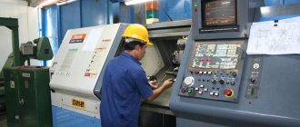
For many years, thyristor power supplies have been produced and used in industry for galvanic processes, which have a power step-down transformer operating at a frequency of 50 Hz, a rectifying thyristor bridge with a control unit, and a choke to reduce output current ripple. The disadvantages of such power supplies are large dimensions, low efficiency, large output current ripples, low power factor and, as a rule, lack of modularity (when increasing production, modernization is impossible - only a complete replacement with a more powerful one).
Thyristor IP (left) and transistor IP (right)
In recent years, for galvanic processes, transistor power supplies with high-frequency conversion have increasingly begun to be manufactured, which are devoid of the above-mentioned disadvantages of thyristor power supplies and provide a wider range of adjustment of output parameters.
Ripple of the output voltage of a thyristor (left) and transistor (right) IP
Volts and Amps
Don’t want to delve into how volts differ from amperes? We will not. Let's just decide how many we need. Just remember: voltage is volts, current (or simply “current”) is amperes.
1 amp = 1000 milliamps. 1A = 1000mA *With Latin and Russian letters, whether to write “Ampere” with a capital or small letter is a complete pandemonium, get used to it. mA is the same as mA . Volts V (in Russian) or V.
Good news: 2-3 Volts are enough for copper plating; any power supply will supply them without problems.
* Chrome plating and anodizing of aluminum requires relatively high voltages. These processes are clearly not for beginners, so we will focus on copper and nickel plating.
Second news: the required current depends on the area of the masterpiece being created. Approximately 20mA = 0.02 Ampere per square centimeter. For copper plating of one bead, earring, pendant or some small accessories, the current from any power supply is enough.
However, over time, appetites grow. For a bas-relief the size of a palm or for simultaneously freezing 10 large beads, the current strength begins to be insufficient - well, just like money in real life.
* A fist-sized wire lampshade required 4 Amps. Although its area (holes do not count) does not seem so large. At a current of 2A, not only the process speed is half as much as at 4A. You can live with this, but the coating turned out dull. At high current and with shine-forming additives in the electrolyte, the coating becomes shiny and mirror-like. Does not require any polishing or varnishing.
Literature
- Elinek T.V. Advances in electroplating technology. Review of world specialized literature for 2008-2009 // Electroplating and surface treatment. 2010. No. 4, pp. 13…18;
- Babaskina S.Yu., Korbit A.A., Filimonov V.A., Yakubovskaya S.V. Nickel plating electrolytes based on urea melt // Creation of new and improvement of existing technologies and equipment for applying galvanic and their replacement coatings: materials of reports of the republican scientific and technical seminar. Minsk, BSTU, 2011, pp. 31...35;
- Popov A., Popov S. Infineon - the new leader in the IGBT market. Electronics News No. 8/2016.
•••
What do we need
The power supply 1) reduces the voltage from 220 Volts to a small one and 2) rectifies it, i.e. turns a variable into a constant. “Plus” and “minus” in electroplating must be observed. Any network adapter can do this, for example, a mobile phone charger.
What else do we need? 3 - regulator, 4 - indicator. The regulator is a knob that we turn. The indicator shows the current strength. And all this farming in one building. So that wires and parts do not lie chaotically on the table, to the delight of children and the cat.
The cheapest
Chinese brothers, almost twins.
Dazheng PS-1502D and Dasheng PS-1502DD.
The numbers mean 15 Volts, 0 2 Amperes.
Models differ in the set of regulators and terminals. The 1502D only adjusts the voltage using the “coarse” and “fine” knobs. The 1502DD has two knobs on the left that allow you to set the maximum current (current protection) and voltage range.
Price 600-700 rub.
Pretentious glowing voltage and current indicators. Woke up at night, how is my galvanic bath doing? – If the current strength is normal, then it’s good.
Included is a bunch of wires for testing and charging mobile phones.
Unreliable. Manufacturers saved on everything, hence the low price. If it burns out quickly, they are required to replace it under warranty. Instead of handicrafts there will be butting heads with sellers. It is more likely that at high current levels it will fail. It will work normally for 20 minutes, overheat, and begin to show an unrealistic current strength, plus or minus a kilometer. Copper will be deposited, the quality of the coating will sometimes be excellent, but more often terrible. You will spend a lot of time and materials, and you will not get at least a negative experience from which to build on. Because incorrect numbers on the facade will misinform you.
Who buys such power supplies? Poor electronics enthusiasts. Its case and indicators are good; it will be more expensive to buy separately, a paradox. With the help of a tester and their knowledge, craftsmen can control and repair it. Or they redo it right away. They install a good radiator, change the transformer, change the diode bridge and capacitor, change it. - well, you understand. This is a hobby for electronics engineers. But we have something else. The Internet is full of technical details on modifications and modifications, but this is not our way.
Optimal
A decent company at affordable prices is Mastech.
Prices (wholesale) from www.mastech.ru/price.htm
| Name | price, rub. |
| HY1502D | 1575 |
| HY1503D | 1680 |
| HY1505D | 2365 |
| HY1802D | 1745 |
| HY1803D | 1870 |
| HY3002 | 2660 |
Pairs of numbers, like those of other manufacturers, indicate maximum voltage and current. Everyone has an abundance of volts. Amps are important to us. 5 is better than 3. But HY15 05 D disappeared from sale almost everywhere. No matter, but 700 rubles. saved. The price of 15 02 and 15 03 is almost the same. So we focus on HY1503D.
1502 and 1503 can be in this or that case, so look at the numbers. And don't trust pictures on sellers' websites. The model of a vague color has a crooked connection between the case and the front panel. Photo from the official website - I wonder if they chose the worst copy on purpose? I saw these blocks in the store, such curvature is not noticeable.
Retail prices Mastech HY1503D
https://www.electro-tovar.ru 2190 rub.
https://shop.siriust.ru/product_info.php/cPath/23_24/products_id/17049 1660 rub.
https://micromir.ucoz.ru/publ/40-1-0-65 1580 rubles, but Nizhny Novgorod, however.
Advantages:
Normal price, build quality and components, reliability.
Large voltage and current indicators. There are current stabilization and voltage stabilization modes, corresponding to two control knobs.
Flaws:
The choice of modes is fantastically inconvenient .
For electroplating, one regulator is sufficient. It's simple: increase the voltage - the current increases accordingly. According to Ohm's law. It would seem that we use one of two handles on the HY1503D, and that’s okay. Not at all. To enter the desired mode, you need to turn both knobs to the minimum-maximum position when the power supply is turned off, and there is also a 3rd current limiting mode... Even the cheap Chinese one we reviewed has red and green LEDs indicating normal or overload modes. Older Mastech models also have mode indicators or a special switch. All that remains is to memorize the instructions and not make a single wrong move! It's not difficult, but keep in mind: getting used to a particular device will confuse you if you encounter another.
DIY power supply for electroplating
PCB Assembly from $30 + FREE Shipping Worldwide + Stencil
The webinar program includes: Silent Switcher® technology - a combination of high efficiency and ultra-low EMI levels, uModule® technology - highly integrated power supply solutions, micro- and nano-power DC/DC converters, backup power solutions, digital power system management (PSM), optocoupler-free isolated flyback converters. The practical part of the webinar will demonstrate examples of working with Analog Devices tools for designing power supplies.
| Attachments: |
| IMG_4965.JPG [75.02 KiB] Downloads: 2309 |
_________________ About how many wonderful discoveries the spirit of enlightenment is preparing for us.
“When a society has no color differentiation of pants, then there is no purpose!”
Connfly, one of Asia's leading manufacturers of standard connectors, and Compel, as part of a partnership program for warehouse development, are introducing installation panels for microcircuits. The DS1001-01 series sockets are made in a Dual In-Line housing and are designed for multiple placement and connection of DIP integrated circuits into electronic devices.
_________________ About how many wonderful discoveries the spirit of enlightenment is preparing for us.
“When a society has no color differentiation of pants, then there is no purpose!”
Best the enemy of the good .
_________________ Although optics magnify images, looking through an optical sight, all problems become smaller.
_________________ The invention and acquisition of RADIO is the greatest achievement of humanity, which has no equal.
good day everyone, need forced me to make an installation for galvanization, the conditions are quite strict but not impossible, the reactor itself is ready but the question arose about the current source; there are two transformers from UPS each with two windings of 8.5 V, connected in series or in a circuit with a common one point which gives 16V at the output or so in parallel which gives us 8.5V
Let's start with everything about the power supply, let's talk about the current stabilizer. Before this, a thermally unstable linear stabilization circuit melted, of this kind, in fact, everyone understands that at a current above 20A it will heat up fiercely, which is what happened and what happened was that I had a local overheating of the transistors, they shorted out and there was a breakdown of the diodes in the rectifier
I had a strong desire to make a pulse stabilizer, but unfortunately my knowledge of electronics is not enough to make a PWM power supply or similar ones, I desperately ask for help
that's what you need: current stabilizer 1-30a 4.5v power supply 16 volts at the output voltage regulation is desirable but not required long-term operating mode current regulation is required load galvanic bath with resistance changing during the process must be able to hold a given current by changing the voltage pulse or similar in order to get rid of thermal unstable elements
_________________ Nothing strengthens mutual trust more than 100% prepayment! Dmitry, RK3AOR.
where is the processor power bus with low voltage mosfets? I repeat that I have poor understanding of microcontroller circuitry
I found a driver from Intel on the motherboard and this is the basic principle (see attachment) can you advise how to convert it to my needs?
| Attachments: |
| capture-20130109-231845.jpg [235.84 KiB] Downloads: 1847 |
_________________ Nothing strengthens mutual trust more than 100% prepayment! Dmitry, RK3AOR.
transformers 8.5 windings are made of copper wire, 2 squares of X3 wires, that is, 6 square windings
specialties are needed because the resistance constantly jumps during the process, and the process takes about a week (precipitation of salts), so it needs to be held by itself, and there is no latre available
_________________ Everything is not as it seems
I have two transformers but I doubt that I can connect them according to this scheme, one primary, two secondary at 8.5 they are connected with a common point like here
the load is turned on is also interesting, in fact the powder is easy to get, you can try it, I just wonder how long it will take to debug without an oscilloscope
The truth is that it immediately catches your eye that the author himself writes that at least 100 watts of heat will be dissipated by transistors, you will agree that this is a pretty big number, the radiators will turn out to be a whole barathea with airflow
_________________ Don’t interfere! WITH." Why doesn’t the Lord give us a helping hand for so long? And the worst thing is: maybe he’s holding out, but we don’t notice it longer and longer?”
_________________ Everything is not as it seems
I didn’t find the circuit diagrams of these models, a pulsed current source with current stabilization is enough for me, the circuit from the motherboard will do, all that remains is to decide how to control it, and come up with a two-layer signet, all the parts can be removed directly from the motherboard, although everything will be in the SMD with what it is connected a number of difficulties, and it will be difficult to catch errors without an oscilloscope
True, the stabilizer from the motherboard is a microscope, it’s not even nails, it’s an electronic microscope to chop stones
Last edited by Darknew Thu Jan 10, 2013 02:51:05, edited 2 times in total.
_________________ Nothing strengthens mutual trust more than 100% prepayment! Dmitry, RK3AOR.
Time zone: UTC + 3 hours
Who's on the forum now?
This forum is currently viewed by: no registered users and guests: 38
Topic: Rectifier for electroplating
Backlinks
- Backlink URL
- More about backlinks
- Bookmarks & Share
- Submit a forum topic to Digg!
- Add a forum topic to del.icio.us
- Post to Technorati
- Post on VKontakte
- post on Facebook
- Post to MySpace
- Post on Twitter
- Post to LiveJournal
- Post to Google
- Post to Yahoo
- Post to Yandex.Bookmarks
- Post to Links@Mail.Ru
- Reddit!
Theme Options
- print version
Rectifier for electroplating
I would like to assemble a rectifier from improvised items that is capable of outputting 200 amperes at 12V. Preferably adjustable. I'm thinking about a diode bridge and a latre. but alas, I can’t find anything for 200A latrov: russian_roulette: Help please!
- Share Share this post via
- Digg
- Del.icio.us
- Technorati
- Post on VKontakte
- Post on Facebook
- Post to MySpace
- Post on Twitter
- Post to LiveJournal
- Post to Google
- Post to Yahoo
- Post to Yandex.Bookmarks
- Post to Links@Mail.Ru
- Reddit!
Are you planning on converting your swimming pool into a galvanic bath? Look, industrial galvanic baths operate at 5-15 volts, 5-20A in total. With such currents, it is no longer a galvanic bath, but an electric arc bath, for melting metal.
PS. And LATR will not be enough for electroplating. In electroplating, stability and accuracy of maintaining a certain current density are very important. Those. By adjusting the current manually, looking at the ammeter, you are unlikely to get anything useful. You will still have to make a current stabilizer.
Last edited by UA9JDD; 02/16/2008 at 12:18 pm.
- Share Share this post via
- Digg
- Del.icio.us
- Technorati
- Post on VKontakte
- Post on Facebook
- Post to MySpace
- Post on Twitter
- Post to LiveJournal
- Post to Google
- Post to Yahoo
- Post to Yandex.Bookmarks
- Post to Links@Mail.Ru
- Reddit!
Dear, you are wrong - when chrome plating, the current is 150-200A/dm2
- Share Share this post via
- Digg
- Del.icio.us
- Technorati
- Post on VKontakte
- Post on Facebook
- Post to MySpace
- Post on Twitter
- Post to LiveJournal
- Post to Google
- Post to Yahoo
- Post to Yandex.Bookmarks
- Post to Links@Mail.Ru
- Reddit!
I saw live one diode rectifier with a “latr” weighing 200 kilograms, if the memory is not changed, its maximum current was 400A. For a home, for a family, 200A is clearly overkill; this is for a bathtub with a minimum volume of 500 liters. Erioh, if you really need such current, I recommend taking a look at an industrial unit