GOST 6507-90Group P53
INTERSTATE STANDARD MICROMETERS Technical conditions Micrometers. Specifications
MKS 17.040.30OKP 39 3410; 39 3470
Date of introduction 1991-01-01
INFORMATION DATA
1. DEVELOPED AND INTRODUCED by the Ministry of Machine Tool and Tool Industry of the USSR
2. APPROVED AND ENTERED INTO EFFECT by Resolution of the USSR State Committee for Product Quality Management and Standards dated January 25, 1990 N 86
3. THE STANDARD IS FULLY IN COMPLIANCE WITH ST SEV 344-76 - ST SEV 352-76, ST SEV 4134-83
4. The international standard ISO 3611-78 has been introduced into the standard
5. INSTEAD GOST 6507-78
6. REFERENCE REGULATIVE AND TECHNICAL DOCUMENTS
| Designation of the referenced technical document Item number |
| GOST 2.601-952.2.3 |
| GOST 8.001-803.2 |
| GOST 8.383-803.2 |
| GOST 9.032-742.1.1.18, 2.1.2.3 |
| GOST 9.303-842.1.1.18, 2.1.2.3 |
| GOST 2789-732.1.1.9, 2.1.2.5 |
| GOST 3882-742.1.1.7 |
| GOST 9038-902.1.5.2 |
| GOST 9391-802.1.1.8 |
| GOST 13762-862.3.4, 2.4.1, section 5 |
| MI 782-854.1 |
7. By Decree of the State Standard of October 12, 1992 N 1354, the validity period was lifted
8. EDITION (August 2004) with Amendment No. 1, approved in October 1992 (IUS 1-93)
This standard applies to micrometers with division values of 0.01 and 0.001 mm.
The requirements of this standard are mandatory. (Changed edition, Amendment No. 1).
Specifications.
2.1. The measuring surfaces of the micrometer are equipped with carbide tips. A micrometer head with a division value of 0.1 mm is used as a reading device. The microscrew in the micrometer head is hardened, with a ground thread. The micrometer brackets are thermally insulated and equipped with thermal insulation pads to prevent the effects of hand heat. The measuring force during the measurement process is 700-900cN.
2.2. Technical characteristics of MK type micrometers are given in Table 1.
Table 1
Technical characteristics of micrometers type MK
| Model | Measuring range, mm | Permissible measurement error, micrometer, class micrometer | Value of division | Nominal size of installation standard | Dimensions, mm | Weight, kg. | |
| 1 | 2 | ||||||
| MK25 | 0-25 | 0,0020 | 0,0040 | 0,01 | — | 137×71×26 | 0,31 |
| MK50 | 25-50 | 0,0025 | 0,0040 | 0,01 | 25 | 163×73×26 | 0,35 |
| MK75 | 50-75 | 0,0025 | 0,0040 | 0,01 | 50 | 192×90×26 | 0,43 |
| MK100 | 75-100 | 0,0025 | 0,0040 | 0,01 | 75 | 217×106×26 | 0,55 |
Measuring range with a smooth micrometer
Due to restrictions on the stroke of a screw with a precise thread, smooth micrometers are produced in certain measurement ranges - from 0 to 25 mm and up to 900-1000 mm. The upper limit of measurements is indicated in the designation of the device: MK-25 - from 0 to 25 mm, MK-50 - from 25 to 50 mm, etc. up to MK-1000 - from 900 to 1000 mm. All tools from MK-50 and above are supplied with an installation gauge for setting “to zero”. There are also instruments with digital display, which greatly facilitates measurements.
In addition to the measurement range, an important characteristic of a smooth micrometer is its accuracy class - 1st or 2nd. The permissible error limit of the device depends on it. Depending on the measurement range, instruments with accuracy class 1 have an error of 2 to 6 microns, and with accuracy class 2 – from 4 to 10 microns.
Accuracy of measurement is the key to correct production of parts. Therefore, we, the Mecca Tools online store, offer only accurate and proven measuring instruments from well-known Russian and foreign manufacturers. You will find a wide range of offers, professional advice, reasonable prices and fast delivery to any region of Russia.
Device and principle of operation.
5.1. The micrometer consists of a bracket, a micrometer head and two rods equipped with carbide tips, which prevent abrasive wear of the micrometer rods, ensuring high measurement stability. One of the rods is fixed fixed, the other is movable, moved using a micrometric head screw.
5.2. The part to be measured is clamped between the rods until it stops.
5.3. The dimensions of the part being measured are measured by directly assessing the coincidence of the scale divisions with the vernier divisions.
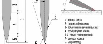
How does a micrometer work and what does it consist of?
Micrometer structure: 1 - heel, 2 - screw, 3 - stem scale, 4 - drum, 5 - bracket, 6 - clamping device, 7 - ratchet.
The device of a micrometer is very simple. All micrometer mechanisms are located on the bracket (5), and the heel (2) is attached to it. It acts as a stop during measurements. At the opposite end of the bracket, the stem (3) is rigidly fixed; it is a hollow cylinder. A scale is marked on the stem; its division is usually 0.5 mm. Inside the stem there is a screw pair and a fastening mechanism (6). The smooth part of the micrometer screw extends from the stem into the measuring area and ends in a flat measuring surface. The opposite part of the micrometer screw is rigidly connected to the drum (4). The drum has a scale that allows you to count hundredths or thousandths of a millimeter.
Important! For household measurements, micrometers are most often used, the unit of measurement of which on the drum is 0.01 mm.
A ratchet (7) is located at the outer end of the drum. It limits the torque applied by the human hand when rotating the screw, which helps avoid deformation of the part during measurements. The ratchet is also used during the preliminary adjustment of the element (we will talk about this in more detail below).
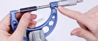
Preparing for work.
6.1. Before starting work, familiarize yourself with the passport for the indicator.
6.2. Before using the micrometer, thoroughly wipe the measuring surfaces, check the smooth movement of the microscrew and the zero setting. If the zero setting is off, bring the measuring surfaces into contact with each other or with the setting standard, and secure the microscrew with a stopper. Then unscrew the drum locking screw with a wrench so that by rotating the drum you can align the zero stroke of the drum with the longitudinal stroke of the stem. At the same time, make sure that the distance from the end of the conical part of the drum to the edge of the zero stroke of the stem closest to the end does not exceed 0.15 mm. Secure the drum locking screw with a wrench.
How much does a USSR micrometer cost?
Micrometer
0 - 25 mm
USSR
GOST 6507 - 53 - buy in Moscow, price 1,590 rubles, posting date: 07/14/2021 – Measuring tools
Interesting materials:
What is import bookmarks? What is impulsive behavior? What is impulsive? What is inhibit? What are Interfix examples? What is interpret? What is the recording interval on a DVR? What is interval viewing in Vlookup? What is Inverter Control? What is an ion and how is it different from an atom?
Acceptable micrometer errors
Micrometer - Acceptable micrometer errors
This measuring device is designed for precise measurement, so you need to know the accuracy of the micrometer. It was invented by scientist Laurent Palmer in the 19th century and was first called a circular vernier caliper. The Americans became interested in it when they saw it at the Paris exhibition, after which its production and promotion began. Now it is a common, practical and popular tool for measuring the diameter of the outside of a part, its thickness, and width. The design is simple. The device quickly measures with very high accuracy.
Indispensable for the production workshop, in linear measurements. Known to every machine operator, mechanic, and designer. Diverse in its design. The universal range of surfaces measured by it is very wide.
Well-known companies specialize in the production of MK: Swiss Tesa, Japanese Mitutoyo, German CarlMahr, domestic CHIS and KRIN. The Chinese are treated with caution.
Their quality is high, they have a grinding appearance, there are no gaps in the contact of the working parts, and they are made of especially strong, hard metals. This ensures the bolt advances without deforming the end plane. It is absolutely anti-corrosion and wear-resistant. The tool follows Abbe's rule, which improves accuracy.
There are two types of MK:
- mechanical, have a dashed plane, vernier;
- digital or electronic.
They have analogue or digital displays.
Working principle of a micrometer
Micrometers may differ slightly in design, but the principle of operation is the same - the part is placed between the stationary heel of the device, after which it is secured with a screw that rotates in a threaded bushing.
When the device is firmly fixed, you will hear a corresponding click of the drum. Now you need to take measurements. As we have already found out, the micrometer has two scales - a fixed one on the stem (in mechanical structures, the division value is usually 1 mm), then we look at the data on the rotating drum scale (these divisions show fractions of a millimeter). There are 50 divisions on the drum, the microscrew pitch is 0.5 mm. A full revolution of the drum gives us a movement of the microscrew by 0.5 mm. Thus, by adding the dimensions from two scales, we obtain the exact size of the part.
Important! When working with the tool, special attention should be paid to the tightening force of the screw. Exceeding the permissible limit can lead to damage to the thread of the device or deformation of the measured object.
Types of micrometers
The following types of micrometers are available for various measurement objects:
- Sheet micrometers - for measuring the thickness of sheets.
- Smooth micrometers - for determining the size of objects with a smooth surface.
- Lever micrometers – equipped with a lever-toothed head for measuring products with complex configurations.
- Pipe micrometers - for determining the dimensions of pipe walls.
- Wire and thread gauges - for measuring thin products.
- Digital micrometers – equipped with an electronic sizing system and a digital scale.
Micrometric depth gauge
This device consists of a basic base, a microbolt with measuring limits of 25 mm is fixed in it, and there are also replaceable measuring inserts of various lengths. The limit for measurements is 300 mm.
Such devices, like MK, are mechanical, digital devices.
The measurement inaccuracy with a minimum insert is 5 mm.
The error includes:
- Inaccuracy of the measuring unit.
- Inaccuracies in flatness and parallelism of the screw with the heel. They occur when turning corners or stopping. This type of inaccuracy comes in different shapes (round, flat). There are also inaccuracies of objects with force during measurement.
- Change in bracket due to force.
- Incorrect installation measures.
- Inaccuracy due to temperature effects is typical for large instruments.
- Electrical components may malfunction in electronic devices.
An error is allowed for the head, if it acts as a separate device, within the limits established by GOST 6507-90. There are special systems with error limits for instruments. They have indicators that depend on the measurement limits. The inaccuracy grid indicates the permissible error G of the device at the measurement boundary point.
These limiting indicators consist of the inaccuracy of the micrometer unit, the inaccuracy due to the deformation of the instrument brackets, the bumpiness, and non-parallelism of the measured planes.
Calibration and adjustment (verification) of the micrometer are performed using gauge blocks at several points of measurement boundaries, respectively, ISO 3611:2010, DIN 863, GOST 6207-90. They are taken to find out the G value, that is, the maximum inaccuracy of the device at all points of the measurement range. Here are the standard, desirable parameters for gauge gauges, for setting up the device: 3.1; 6.5; 9.7; 12.5; 15.8; 19.0; 21.9; 25 mm.
How to measure with a micrometer
Working with a micrometer requires high precision and accuracy. Before starting measurements, let us once again recall the main points of handling the device.
Basic rules for using a micrometer
A micrometer, like any other device, requires careful and correct handling. To improve the measurement accuracy of the device, the following points must be taken into account.
- If the device has a holder, which is most often attached to a bracket, it must be firmly fixed.
- Be sure to wipe (this has been discussed more than once today) the surface of the heel and screw jaws.
- Zero readings are verified. If the display is incorrect, this device must be reconfigured.
- Do not use excessive force when fixing a part with a ratchet! The surface of the clamping mechanisms is made of high-strength materials, so if pressed excessively, they can damage the part being measured.
- It is better to store the micrometer in a special case or bag.
Electronic and laser devices are very sensitive to mechanical damage. It is better to store them in special cases.
How to measure with a micrometer correctly
Let's look at an example of how to use a micrometer:
| Illustration | Description of action |
| To control measurements we use fishing line. The manufacturer claims a thickness of 0.28 mm. | |
| Before starting the measuring process, you should unscrew the screw so that the distance is slightly larger than the fishing line by rotating the drum. In this case, you should not use a ratchet! The fishing line may simply be flattened. | |
| Using the upper part of the stem scale, we determine the number of full mm. Moreover, if on the lower half the last visible mark is to the right, then we add another 0.5 to the resulting value (this is why the lower half of the scale is offset relative to the upper). | |
| As we see, the manufacturer cheated with the data. The line exceeds the declared value by 0.02 mm. Total diameter 0.30 mm. Do not forget that for correct calculation, to the number shown by the cylinder, we add the value from the drum scale, the division value of which is 0.01 mm. |
How to Adjust a Micrometer and Check Calibration Accuracy
During operation, the micrometer scale periodically gets lost. Therefore, it is advisable to calibrate the device before each use. To do this, you need to completely tighten the screw and see if the zero mark on the drum coincides with the horizontal mark on the stem. If necessary, you can repair the micrometer yourself.
If these marks do not match, then you should twist the stem using a special key that is included in the kit.
To check the measurement accuracy of a micrometer with a measurement range of 25 - 50 mm, 50 - 75 mm and more, corresponding standards (gauge gauges) are used, the size of which is known to hundredths of a millimeter. The standard, which has a clean end surface, must be clamped without distortions between the measuring surfaces of the device using a ratchet force of several clicks. The obtained value is compared with the known one, and if necessary, the micrometer is adjusted.
Setting the micrometer to zero
Let us consider in detail how to adjust the micrometer to the zero mark, with a working range of 0-25:
| Illustration | Description of action |
| Before selecting the gap to zero, it is necessary to clean the working surface of the heel and screw jaws. To do this, unscrew the screw a little, take a piece of glossy paper (a fragment of a magazine cover or postcard will do). We clamp the fastener together with it and pull out the piece of paper. This way we will clean our working tools from possible dust, debris and dirt. | |
| We bring the heel and the screw together and tighten the fixing screw. This is necessary in order to fix our device at the zero mark in the future. | |
| Using a special wrench, loosen the drum and remove it. Our task is to return the drum to the position that would correspond to the zero mark. | |
| For precise adjustment, the end of the drum must stop clearly at the zero mark of the stem. And the zero mark of the drum scale should stop opposite the longitudinal stroke. |
Line plane devices
The main parts are screw, micrometric parts. The moving surface for measuring (the end of the screw) is connected to the drum for reading. Its revolution is equal to the thread pitch of the bolt. The standard step is 0.5 mm, the drum element has 50, 100 strokes. The price of the reference stroke is 0.01 mm, 0.05 mm. The more precise the threaded element (manufactured with maximum precision), the better the device works. The micrometric element is a separate measuring part - the head.
It is available in MCs of various devices and types: internal gauges, depth gauges, stationary structures. This is the main measuring unit. In it, the bolt moves with the drum element relative to a firmly fixed bar with a twist. The unit is often equipped with two scales: circular (for fractional scales) and linear (for counting full rotations of the bolt).
There is a linear plane with strokes on the outside of the stem. The price of the scale line is equal to the bolt pitch, if it is 0.5 mm, then two scale sections are applied with a stroke of 1 mm, they are moved together by 0.5 mm.
The range of the screw determines the length of the scale (usually 25mm). There is a circular scale on the bevel of the drum element, its end is an indicator for the linear plane. For a circular plane, the indicator is a longitudinal line on a linear one.
The drum has a graduation diameter of 1 mm. For fractional dimensional grids in a circle, sometimes a vernier is used, the same as in a vernier caliper with a reading without parallax.
The vernier has a stroke size of 0.001 mm; its use is advisable for readable mesh fractions when it is below the stroke error.
The special design of the micrometer (drum ratchet, clutch) stabilizes the forces during measurement. The design has a device that locks the bolt. The measurement planes are parallel end planes on a micrometric bolt with a heel (it is opposite the head), their standard width is 8 mm. There are devices with a size of 100 mm, and the diameter of the working planes is made smaller (6.5 mm). Devices with a bottom border of 25 mm have an installation measure.
In most cases, the price of a stroke is 0.01, 0.05 mm, and a vernier is 0.001 mm. For diameters greater than 500 mm, there is a type of micrometer with brackets made of tubular parts made by welding. They are equipped with thermal insulation. The staples are available with a measurement limit of 100 mm and are equipped with replaceable ends. The length can be increased by 25 mm, the limits of their measurements are up to 1500 mm. The error for them is calculated by the formula: U = ±(6 + L/75) µm, where L is the maximum measurement limit in millimeters.