Varieties
Steady rests are divided according to various factors: dimensions, methods of fastening the product on a lathe, additional structural elements, weight, number of fasteners.
Fixed rest
A fixed steady rest is used to hold long parts. The part is secured to the equipment using mounting bolts that are screwed into the support plate.
The peculiarity of fixed structures is that it has three cams, one of which supports the top, the other two - the bottom. For fastening to workpieces, the fixed steady rest has a folding hinge, which simplifies this process.
When you need to rough a part, you need to clamp the jaws as tightly as possible. Otherwise, vibrations may appear that will disrupt the accuracy of the cutters and lead to defective parts.
Movable steady rest
The moving parts have several differences from the previous ones. The lathe has a longitudinal support on which the steady rests are attached. Thanks to this, the movement of the cutters with the additional part occurs simultaneously. This allows for more uniform processing. The cutting tool does not jam and maintains its integrity for a long period of time.
Another feature of the moving part is the presence of two cams to stop the part. One is located on the top of the structure, the other on the side. The role of the third stop is performed by the cutter.
Machining parts in steady rests
Machining in a steady rest
Long and thin parts, the length of which is 10-12 times greater than the diameter, bend during turning under the influence of their own weight and cutting forces, as a result of which they receive a barrel-shaped shape - thicker in the middle and thinner at the ends. This can be avoided by using a special support device - rests. When using steady rests, you can grind parts by removing chips of a larger cross-section, without fear of their deflection.
Lunettes can be fixed or movable.
Fixed rest
The fixed steady rest (Fig. 339) consists of a cast iron body 1, to which a hinged cover 6 is attached using a bolt 7, which makes installation of the part easier. The base of the body of the steady rest is shaped according to the guides of the frame, on which it is secured with a bar 9 and a bolt 8. Two cams 4 are moved in the body using adjusting bolts 2, and one cam 5 is moved in the cover. Screws 3 are used to secure the cams in the required position. The device allows you to install shafts of various diameters into the steady rest.
Rice. 339. Fixed steady rest
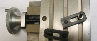
Before installing the workpiece into the steady rest, you need to machine a groove in the middle for the cams, a width slightly larger than the width of the cam (Fig. 340). If the workpiece has a large length and a small diameter, then when turning such a groove, deflection of the workpiece itself is inevitable. To avoid this, first machine an additional groove closer to the end of the workpiece and, having installed a steady rest in it, machine the main groove in the middle.
Fig. 340. Turning a part using a fixed steady rest
Sometimes the workpiece can be so long and thin that one main groove is not enough. In such cases, two or more additional grooves are machined.
Machining in a steady rest
Processing in a steady rest is carried out as follows: grind the part to the groove, i.e., to the place where the steady rest is located, then turn the part over, install it again in the centers and, again securing it in the steady rest, grind the rest of the shaft.
In some cases it is not practical to grind additional grooves; then apply the method shown in Fig. 341 and 342. Cylindrical bushing 2 (Fig. 342) is put on the middle part of the workpiece 1 and, using bolts 4, is installed concentrically with the axis of the workpiece. The concentricity of the bushing is checked with indicator 3, as shown in Fig. 342.
The workpiece with the sleeve in place is installed in the steady rest (Fig. 341), and the ends are placed in the centers and ground to the steady rest. After this, the steady rest is opened, the workpiece is removed from the centers and the sleeve is removed. Then the workpiece is turned over and, having installed the cams of the steady rest along the diameter of the turned part, the remaining section of the workpiece is turned.
Fixed steady rests are also used for cutting ends and trimming the ends of long parts. In Fig. 343 shows the use of a stationary rest when cutting the end: the part is fixed at one end in a three-jaw chuck, and the other is installed in the rest.
Rice. 342. Checking the concentricity of the installation of the bushing for processing a part in a stationary rest
Fig. 341. Turning a part with a bushing in a stationary rest
In the same way, you can machine precise holes from the end of a long part, for example, bore a conical hole in the spindle of a lathe or drill such a part along its entire length.
The cams of the fixed steady rest must be installed exactly along the diameter of the part with the center on the spindle axis; they should not be clamped tightly. Surface of the part supported
Rice. 343. Trimming the end of a part installed in a chuck and a fixed rest
Rice. 344. Fixed steady rest with ball bearings for high-speed processing
cams, it is necessary to lubricate with oil to reduce friction and prevent the formation of scoring.
Steady rests with hard jaws are not suitable for high-speed machining due to rapid wear of the jaws.
Rice. 345 Turning a part using a movable steady rest
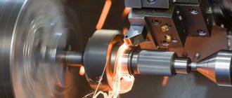
For high-speed processing, steady rests with roller or ball bearings are used (Fig. 344). In this case, sliding friction is replaced by rolling friction, which reduces the heating of the workpiece, which is important when working at high cutting speeds.
Movable steady rest
The movable steady rest (Fig. 345) is fixed to the caliper carriage. Together with it, following the cutter, it moves along the part being turned and supports it at the point where the force is applied, protecting it from deflection. A movable steady rest is used for finishing turning of long parts. It has only two cams. They are pulled out and secured in the same way as the cams of a fixed rest.
Similar materials
Movable steady rest and its structure
This device is located on the longitudinal support of the machine. Thanks to this arrangement, the mobile steady rest performs movements with the same trajectory as the machine cutter. Thus, the pressure on the part from the turning tool is reduced. The movable type of device also has its own classification:
- According to the clamp system. There are roller and cam fixation systems. Fastening with rollers ensures convenient sliding of the workpiece during work, while cams provide better control over the position of the part.
- According to the specifics of processing. Different types of tools can be used for grinding, turning or creating bearings.
- By type of clamp settings. In these devices, the cams or rollers can be adjusted manually or using a hydraulic drive.
- By the number of fasteners. Most devices are manufactured with three cams, but there are models with more clamps.
The mobile steady rest is attached to the support carriage and is used in cases where there is a need to perform clean turning or make threads on long workpieces. Like a fixed steady rest, thanks to adjustable cams, it has the ability to fix parts of completely different diameters.
The maximum diameter of the workpiece being processed depends on the device model and ranges from 20 to 250 mm. Key elements of the movable steady rest design:
- Hinged lid.
- Blank for processing.
- Pads.
- Screws for installation.
- Frame.
Before starting work on the part, it is necessary to grind the area in which it will come into contact with the steady rest clamps. The jaws must be clamped smoothly and slowly for secure and even clamping. With proper fixation, the workpiece will remain motionless even under very heavy loads. After completion of the work, the cams are gradually retracted or the cover of the device is opened.
Important nuances
Please be aware of the following important points before purchasing or using these devices:
- Turning the place where the part comes into contact with the steady rest clamps can only be carried out in the case of rough work. If the part has fixed dimensions or its surface has already been pre-treated, then there is no need to pre-turn it.
- If the operator is carrying out finishing work, but there is a need to securely fasten the part, then a special cylindrical pad roller can be used. In diameter, it should be similar to the diameter of the workpiece being processed at the point of its contact with the cams of the steady rest. One part of the lining is fixed in the device, and the other in the machine chuck.
- When working with very thin or long parts, it is not always possible to pre-grind the neck for installation in the rest. In this case, it is recommended to make several temporary necks with maximum proximity to the headstock.
- It is advisable to adjust the machine cutter with a negative angle. Otherwise, it may push the part away from itself, as a result of which the processing accuracy will decrease.
The main manufacturers of steady rests are Jet (USA), Dnepropress (Ukraine), Astrakhan Machine Tool Plant (Russia), Zmm (Bulgaria), Proxxon (Germany), SMTCL (China).
Republished by Blog Post Promoter
Advantages and disadvantages
When using steady rests, the following positive qualities are noted:
- machine operator safety;
- accuracy of product dimensions;
- vibration reduction;
- prevention of workpiece and tool destruction;
- expansion of the range of sizes of processed parts;
- simple design;
- reliability.
Among the shortcomings, the short service life of the elements directly in contact is noted. To reduce loads, the supports are made of cast iron or bronze. Roller bearings are more durable, but support bearings are quickly destroyed, especially if their feed is mechanized.
Advantages and disadvantages of the device
A correctly installed steady rest significantly improves the accuracy of the work performed, ensures the integrity of the part, facilitates the operator’s work and ensures safety. The device expands the maximum and minimum parameters of the workpieces being processed, and also provides additional angles for fastening parts. The device is reliable and easy to use.
A mobile steady rest is easier to install, while a fixed one provides greater accuracy. It is necessary to begin work by carefully checking the fixation of the workpiece. You should pay attention to the fit of the cams.
What does it consist of?
The fixed steady rest is rigidly fixed to the machine bed. The correct orientation relative to the chuck is organized by installing a frame on a flat and prismatic guide along which the tailstock moves.
Composition of the device:
- base;
- pressing bar;
- fixing screw;
- hinged lid;
- hinge;
- hinged bolt;
- screw;
- supports - 3 pieces;
- screw mechanisms;
- heads.
The operating principle is as follows: having installed the steady on the frame, it must be secured at the required distance from the chuck. To do this, a pressing bar is used, which is tightened with a screw and rests against the lower surface of the guides. After which the lid is opened and the workpiece is secured.
After fixing the workpiece, the lid closes. A reliable connection is ensured by a nut with a hinged bolt. The turner, rotating the heads of the screw mechanisms, moves the supports towards the shaft. The final fastening is carried out with the part rotating.
It is worth remembering that when processing round-rolled shafts, after forging or stamping, before starting work, the place where the supports come into contact with the workpiece must first be ground. The outer surface of the workpiece is uneven and the steady will not perform its function. But if finishing processing is carried out, then there is no need for grooving.
The movement of the supporting surfaces is carried out not only manually with a screw pair, but also with the help of drive devices. In most cases, a hydraulic drive and hydraulic cylinders are used for this. The clamping force is regulated by pressure in the hydraulic system.
The movable steady rest is so named because it moves with the carriage on which it is attached. For this purpose, manufacturers have provided two threaded holes. It moves along with the cutter in the longitudinal direction, so processing stepped shafts is difficult or is limited in processing length.
The lathe and steady rest are installed separately. The use of movable devices is typical for thread cutting and finishing turning over long distances.
The structure includes the same elements as the fixed one, with the exception of the pressing bar and the fixing bolt.
Rules for using mandrels
There is a list of rules for using turning mandrels:
- The accuracy of the mounting hole must be no lower than the seventh quality, and the surface cleanliness must be no worse than Ra 1.0.
- The tool must be positioned along the center axis of the machine.
- The contact surface of the turning mandrel should be maximum.
- To avoid deformation and deformation of the tool during the cutting process, the hardness of the holder collet material should not be less than 44 HRC.
- The greater the overhang of the mandrel, the more securely it must be secured. It is strictly forbidden to fasten long mandrels by pressing screws to a cylindrical or other surface. To install long mandrels, it is necessary to use additional equipment.
Do-it-yourself steady rest for a lathe
Hello, dear DIYers! This article will be of interest to anyone who has a lathe in their workshop. For both amateurs and professionals. The author of the “Make it Extreme” channel, often faced with the need to process large parts on a lathe, decided to make a steady rest for him.
This device allows you to process workpieces of large diameters and lengths with high precision. With its help, additional support is created for the second edge of the workpiece, which is difficult to secure with a standard tailstock. The author has such a lathe, and it is for this that the device will be made.
Tools. 1. Lathe. 2. Drilling machine. 3. Welding machine. 4. Plasma cutter. 5. Bulgarian. 6. Miter saw. 7. Small things - hammers, drills, etc. Materials. Steel plate 25 mm thick. Steel strip, sheet. Hairpin diameter 12 mm. Bearings, bolts, washers, nuts... Paint.
To begin with, measure the dimensions of the guides.
Then, the lowest part of the base is cut out of a steel plate, on which the steady rest will be attached. He tries the workpiece against the guides; it will be located under them.
A hole for the clamp is drilled in its center, starting with small drill diameters.
Then he turns the workpiece over and welds the second half of the bolt head.
Installs it under the guides and puts on the second part, puts on the washer and screws on the nut.
The dimensions are correct, and since the upper part was only tacked by welding, the seams are welded.
The last, uppermost part of the base is made from the same steel plate. And in order to have access to the clamping nut with a socket wrench, drill a hole in it with a crown.
And here is the plasma cutter.
Part of the circumference of the body blanks is cut off so that they have a smooth edge for installation on the base.
Drills holes for connecting bolts.
Tightens the bolts.
Prepares the base for welding.
The seam turns out - just a sight for sore eyes.
Cleans the seam using a grinder.
Pay attention to the profile of the base. Starts assembling the bodies of the adjustable clamps, three of them will be needed
For them he uses a steel strip.
Place the extended nuts between the strips and clamp them with a clamp.
Having removed the nuts, he welds the seams.
Having marked the resulting rectangular profile pipe, it is cut with a miter saw. The pipe profile turned out to be rectangular due to the shape of the nuts; the hexagon does not fit into the square.
Clamps the workpiece in the lathe chuck and grinds off part of the thread.
Cuts a new thread first with a chisel, then with a tool.
Twists the “lamb” (handle - twister).
This is what the assembled clamping mechanisms will look like.
Having placed the clamps in places on the body frame, welds them.
I installed bearings at the ends of the clamps, checked the toe in the center and the alignment of the machine chuck.
Everything is ready, you can check it on a pipe blank. Place a very thin plate between the bearing and the pipe so that the bearing does not get crushed.
After tightening the fixing screw, the plate is removed.
The rest of the clamps are adjusted in the same way.
Thanks to the author for the excellent execution of such a very necessary device!
Good ideas and an obedient instrument to everyone!
Source
Become the author of the site, publish your own articles, descriptions of homemade products and pay for the text. Read more here.
Why should you buy a tablet?
In order to simplify the definition of the term “tablet computer” as much as possible, we can say that it is actually the same as a laptop or PC. The main difference between a tablet computer and a personal computer is its mobility (the gadget can work without any wires, not counting the charger). You can take such a gadget with you on a long trip to listen to music or stay in touch with friends and colleagues. In addition to mobility, a tablet differs from a laptop or PC:
- Smaller dimensions and weight
- The so-called touchscreen (touch screen)
- Lack of a keyboard (on most models it is possible to connect it, but many successfully make do with an on-screen “keyboard”)
- Ability to expand internal memory by installing an SD card (on most devices)
- Some models have a camera and a SIM card slot, which turns the tablet into a multifunctional phone
Beginners are not recommended to immediately launch them and try to figure out what’s what, since such a variety of software can easily get confused.
Types of steady rests for lathes
Steady rests for lathes come in different types. In addition to differences in structural elements, sizes, types of mounting on the frame, all tools without exception can be classified into one of two main categories:
- Lathe lunettes, which are called stationary. They are installed permanently at any working point and remain there during the entire processing cycle.
- Devices that are called movable. Their location on the bed changes depending on where the turning tool moves along the workpiece.
Steady rests for a grinding machine have a similar design to the stationary fixtures of a lathe. Their supporting parts are coated with a material that does not allow the grooves on the workpiece to be wiped, such as babbitt.
Fixed lunette
A fixed steady rest is a device for a lathe, the purpose of which is to support a long workpiece. This allows for more precise processing of the product and eliminates vibration. The method of attaching the equipment to the frame is through a flat base plate and a bolted connection. A characteristic feature of all fixed turning steady rests is the presence of three rollers, or cams, two of which support the part from below, the third provides support from above. In order to install the workpiece on the fixture, the upper part of the latter can be hinged, and after securing the part, it returns to its place and is fixed with a special bolt. The design of fixed turning equipment fully corresponds to the design described in the section “Design and purpose of the steady rest.”
Lunette of movable design
A movable steady rest is a slightly different support design than a fixed device. It is no longer attached to the frame, but to a longitudinal support on a lathe. This allows the system to move simultaneously and in the direction in which the cutting tool is moving. That is, it is located opposite the incisor itself. The main purpose of a movable turning rest is to eliminate bending of thin and long parts under the influence of a cutter. This allows you to avoid jamming of the tool and damage to the product. The movable turning device has the following structural elements:
- Base with mounting holes. This is an all-metal element that is shaped like a question mark. There is no need for a folding part, as with a fixed lathe rest, since the part can easily be inserted into the fixture from the side.
- Support cams, of which there are two. One is located on top, the other on the side. The third support here is the cutter itself.
- Screws for extending and securing the jaws.
Structure of a static steady rest
The main task of a static steady rest is to support large parts while working with them. The stationary device is installed on the frame using the lower gearing. This device helps improve the accuracy of the workpiece and avoid unnecessary vibration. A static device has several key elements:
- base;
- hinged lid.
The design of the device for working fixation is equipped with a hinged bolt with a special head. There are three cams on the lid of the steady and at the base, designed for fixation. By adjusting them, the operator has the opportunity to adjust the device to the size of the part being processed.
Lunette clamps are most often made of cast iron. This helps avoid damage to fragile parts. A special coating is installed on the cams , which serves as protection. Most often, such a protective coating is created by the manufacturers of steady rests themselves.
However, not only the workpieces can suffer from the clamps, but also the cams themselves wear out during operation. Therefore, they are also produced on the basis of hard alloys.
Static steady rests are installed in several stages:
- The workpiece is fixed in the center of the machine.
- Pre-set three cams of the device.
- Grind the neck of the workpiece at the point of its contact with the cams.
- Fix the workpiece.
It should be noted that preliminary turning of the workpiece neck is not always required. Turning may not be performed if the part is pre-processed and has fixed dimensions.
Pros and cons of steady rests
When working on a lathe, you need to know that the use of a steady rest in some cases is simply necessary. This primarily applies to very long workpieces that sag under their own weight.
Therefore, when using a device, it is important to make maximum use of its advantageous aspects and, if possible, avoid negative effects that may appear during the work if done incorrectly.
A steady rest for a lathe, installed according to all the rules, greatly facilitates the operator’s work:
- Processing is easier, since the load on the cutter becomes the same at all points of contact;
- The risk of defects is reduced due to more accurate alignment of the part;
- Processing accuracy increases;
- Increases operational safety by eliminating part runout, the risk of damage and jamming of the cutter;
- Processing speed increases;
- The possibilities of using a lathe are expanded;
- The device is easy to install and requires only precise alignment of the adjusting bolts.
There are certain difficulties in working with a steady rest, which can be avoided with the proper approach to installing the device:
- A poorly aligned mechanism leads to product defects, since the center of rotation of the workpiece shifts relative to the cutter;
- The lunette can only be installed on a pre-treated surface, or a groove can be made for it;
- Devices for a machine with retractable jaws are best used for rough turning of parts;
- For finishing turning, you must have in your arsenal a device with retractable rollers that does not leave marks on the workpiece;
- The installation and adjustment time of equipment reduces the intensity of the production process;
- Purchasing a steady rest is an additional financial cost.
New roller lathe rest
Recommendations for use
Before purchasing or using the device, you need to familiarize yourself with the following important points:
- The place where the clamp comes into contact with the part is ground only during rough work. If the workpiece has a fixed size or its surface has already been processed, there is no need to carry out preliminary turning;
- in case of finishing work and the need for reliable fastening of the part, you can use a special roller - a cylindrical pad. It should be the same diameter as the diameter of the workpiece where it connects to the jaws. One part of the lining is fixed in the device, the other in the machine chuck;
- When working with long and thin parts , it is not always possible to pre-turn the neck. In such cases, several temporary necks should be made, with the closest approach to the headstock;
- It is better to set the machine cutter with a negative angle , otherwise it may push the part away from itself. As a result, processing accuracy will decrease.
Design and principle of operation
Steady rests for lathes are complex elements that consist of several components:
- All-metal base with holes for mounting bolts. With their help, the structure is fixed to the lathe bed.
- Supports with an extension mechanism. There are two types - the first option with rollers, with the help of which the supports can be moved, the second option is the cam type.
- Screws for adjusting the position of the cams.
On fixed rests there is a metal cover that can be moved.
Design and principle of operation of a fixed steady rest
photo: device of a fixed steady rest
- Hinged lid;
- Device base;
- Set screws;
- Pads;
- Part to be processed.
To eliminate the runout of the workpiece on the surface, it is necessary to machine a groove for the holders. When the steady is installed in the right place, you can insert the workpiece, gradually moving the cams to its surface. Once secured and properly centered, you can begin to work. The use of a through cutter for processing helps to avoid deflections, and thanks to the lever bore gauge, you can find out the exact dimensions of the machined inner surface.
Main characteristics and dimensions
| Name | Inner diameter | Processing diameter, from...-to..., mm |
| Fixed lunettes | ||
| 1K62, TS-30 | 150 | 20 — 130 |
| 1K625 | 150 | 20 — 130 |
| 1K62D | 180 | 20 — 160 |
| 1K625D | 180 | 20 — 160 |
| 16K20, 16D20 | 160 | 20 — 150 |
| 16K20, 16D20 | 180 | 20 — 160 |
| 16K25, 16D25 | 180 | 20 — 160 |
| 1M63, DIP 300, 163 | 170 | 20 — 160 |
| 1M63, DIP 300, 163 | 400 | 20 — 380 |
| 1M65, DIP 500, 165 | 400 | 20 — 380 |
| 1M64, DIP 400, 1A64 | 400 | 20 — 150 |
Selecting a steady rest
The fixed steady rest is selected according to the specified dimensions of the part that will need to be processed
The size here is no less important than the type, since in each case the steady rest adds its own range, in which the minimum and maximum size of the clamped part lies. Each model of lathe produces its own models of steady rests that are compatible with their parameters, but there are several manufacturers in different countries who can make their own changes to the material of manufacture and other features. Therefore, when choosing, you need to focus on a stiffer and stronger material.
Therefore, when choosing, you need to focus on a stiffer and stronger material.
"Important! The service life of the product and its quality depend on the material, since during operation it faces enormous loads and a large margin of safety is needed here.”
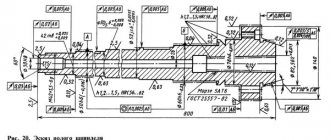
Marking and example of symbol
Each product has its own marking, which reveals the properties of the product. For example, if you take a fixed steady rest 1M65, then you can understand the following:
- 1 – the first digit indicates that it belongs to use on lathes;
- M – the second symbol shows which generation of machines the product belongs to;
- 6 – the number “6” on the third symbol indicates that it belongs to the turning-screw-cutting subgroup of machines;
- 5 – the last number shows the standard size of the steady rest, namely, the centers are 500 mm above the frame.
Manufacturers
- Corvette;
- Red Proletarian (Russia);
- Dnepropress (Ukraine);
- Proxxon (Germany);
- Jet;
- Kuson (South Korea);
- Zmm-Bulgaria (Bulgaria);
- Astrakhan Machine Tool Plant (Russia);
- KraMZ (Ukraine);
- SMTCL.
Design of movable and fixed steady rest
A steady rest for a lathe consists of the following parts:
- An all-metal base with holes for mounting bolts, with which it is installed on a lathe. The fixed steady rest is mounted directly on the bed, and the movable one is mounted on the longitudinal support of the machine, and when processing the workpiece it moves along with the cutter.
- Cam and roller bearings with extension mechanism. A feature of fixed steady rests is the presence of three cams or rollers (two supporting ones on the bottom, one pressing one on the top). A movable steady rest often has two support cams; the role of the third support is assigned to the cutter of a metalworking machine.
- Adjusting screws with which the position of the cams is installed and fixed.
The fixed steady rest is equipped with a hinged cover, which is hinged to the base and rigidly attached to it with a screw.
Design options for homemade lunettes
A steady rest for a lathe is not cheap, so there is little point in buying one if the device is not used very often. It’s easier then to make a steady rest with your own hands. For example, for the IZh1 lathe, you can implement a homemade product using the following design:
- A flange for connecting pipes is used as the base where the cams will be fixed. The flange size is 200 mm in outer diameter and 110 mm in inner diameter. Using a protractor, the flange is divided with a marker into three equal sectors with an angle of 120 degrees each. The sector connection lines will be exactly the places where you need to secure the cam feed mechanisms.
- Instead of cams, you can use three studs with 14 threads and a length of 150 mm each. Handles are welded onto the studs from one end (pieces of wire 8 mm in diameter and 30 mm long, so that it looks like the letter “T” in shape); on the other end, three bronze pointed caps with an internal thread diameter of 14 are ordered from a turner.
- The mechanism for adjusting and fixing the cams can be made from three nuts with an internal thread of 14 (for each cam), two of which are welded opposite each other along lines pre-drawn on the flange.
- To attach the turning rest to the bed, it is necessary to make a special substrate that could move along the runners and be fixed in a certain place. The substrate can be made from a steel angle with a metal thickness of at least 10 mm and a shelf size of 100 mm. The length of the angle should be equal to the width of the frame runners and cover the guides. In order for the shelf to move strictly along the guides, two pieces of 100 mm in length are cut from corners with shelves measuring 15 mm each and a metal thickness of 2 mm. They are placed on runners (opposite each other), and a large corner is placed on top of them, which is secured by welding.
- Next, a hole of 12 is drilled in the main corner so that the substrate can be bolted to a standard metal plate from the lathe headstock mount. The flange is fixed in the headstock, positioned so that one pair of welded nuts looks vertically upward, the corner on the slide is moved close to the flange and welded to it.
- The lunette is removed from the headstock, one nut is screwed onto each cam, an engraver is put on and the cams are screwed into the pre-welded nuts. After this, bronze “caps” are screwed onto the ends of the cams.
Design and purpose of the steady rest
A turning steady is a kind of support. It allows you to hold a cylindrical part in a horizontal position and at the same time does not interfere with its rotation around its axis. Equipment in turning is used in several cases:
- The blank is long and sags in the middle. In this case, the steady rest fixed in the middle levels the workpiece, and during rotation there is no danger that it will rotate like a “spindle”, that is, there will be a thickening in its central part. It will definitely lead to uneven processing on a lathe and can cause vibration, jamming and destruction of the cutter and workpiece.
- It is necessary to process the end of the workpiece. In this case, there is no way to secure the part to this end, since it will be subjected to boring. The turning steady is placed as close as possible to the area of the area being processed. This operation is generally performed last, when the entire remaining length of the part has already been machined clean.
The steady rest can be installed on any metal-cutting equipment, if it is a lathe, milling or grinding machine.
The design contains the following elements:
- The base of the steady rest is an all-metal part. It has a lower plane with holes for mounting bolts, due to which the device is installed and fixed to the lathe bed.
- Lid. It also refers to the base, characteristic of fixed turning rests, made of steel, movably attached to the lower part.
- Retractable supports. They can be made with rollers at the end or operate on the sliding principle (cam-type elements). It is the cams that provide support for the workpiece. To make them less wearable, they are reinforced with carbide coatings. To reduce the impact of the cams on the part (rubbing or pushing), the contact part is equipped with bronze tips.
- Adjustment screws. The purpose of this element is to extend the cams and then fix them in a given position.
What is a steady rest for?
A steady rest is a special machine tool that is used when processing long cylindrical workpieces. When processing long workpieces, turners often face the problem of turning them. It is easier to process a short workpiece due to the absence of the sagging effect. A long workpiece is rotated by a “spindle” and its sagging leads to uneven processing of the part along the length (thickening in the central part) and unnecessary vibrations, which increases the likelihood of scuffing and physical destruction of the cutter. A turning steady rest gives the part stability and increases the accuracy of processing - its purchase is economically beneficial for a metalworking enterprise.
The steady rest is used when performing the following types of work:
- For processing the end part of a cylindrical workpiece - the final part of turning work, when the part has already been machined along its entire length. To bore the end of the part, the steady rest is fixed as close as possible to the area being processed.
- To eliminate sagging of the workpiece, level it and obtain the required characteristics along the entire length of the workpiece.
The steady rest is used in turning, milling, grinding and machine tools of other groups, it reduces the time for setting them up for operation and allows you to automate the process of processing large-length parts.
Exploitation
When working with a steady rest, you must follow the operating rules and take into account the peculiarities of the work process:
- Check in advance the reliability of the display of metal products.
- Use safety glasses, overalls, and gloves while carrying out work.
- Only during roughing it is necessary to process the place where the additional element comes into contact with the working surface.
- Set the cutters at a negative angle so that they do not interfere with the turner’s work.
- Check the integrity of the cams. If cracks or unevenness appear on their surface, the structure needs to be replaced.
- You cannot use homemade devices in industrial production for mass production of metal products.
- When finishing metal products, it is necessary to use a roller pad to additionally hold the workpiece.
For industrial equipment, you need to buy high-quality devices made from durable materials.
Steady rests for lathes are used to carry out more precise work, eliminate vibrations, and the appearance of irregularities. The setup can be carried out by a novice turner by reading the step-by-step instructions. If you wish, you can make a homemade one.
Some features of the operation of steady rests
One end of the workpiece is clamped into a three-jaw self-centering lathe chuck (can be a collet, drive chuck or other device), and the other is supported by the center of the tailstock. The workpiece is in contact with three cams or rollers. At the same time, if the workpiece is not precise (casting or forging), then the contact point of the rollers and cams with the part must be cleaned.
The material for the manufacture of cams of the movable steady rest is, as a rule, cast iron. This alloy has good anti-friction properties, but there is still a danger of damaging soft annealed steel workpieces. Therefore, it is recommended to install bronze or babbit nozzles on the cams. This will protect the finishing surface of the critical product from scratches and abrasion. If it is not possible to produce such attachments, then preference should be given to rolling rollers. This will prevent damage to the surface of the part. However, if the surface of the product in question is subsequently processed on a machine, then there is no need to fear damage.
Types of lunettes
Lunettes have several types of execution and they can be classified as follows:
- By placement method: movable, fixed;
- By type of application: supporting, holding;
- By type of clamping devices: screw, mechanized;
- By type of support: sliding supports (cams), rotation supports (rollers).
Why do you need a steady rest on a lathe? Firstly, when processing long cylindrical parts, the workpiece bends under the action of cutting forces. And therefore, the specified size is not maintained. Secondly, the large distance between the supports during processing causes vibrations, which have a detrimental effect on both the tool and the workpiece itself.
Factory models are manufactured for a specific type of equipment and must comply with GOST 21190–75, 15760−79 and others.
Homemade fixed steady rest.
Homemade fixed steady rest for my lathe Caliber 350/550.
The steady rest is a useful device; it allows you to expand the capabilities of the machine and the accuracy of processing long parts, which can be very useful for my hobby.
A small piece of steel sheet turned up, a little battered by rust and time.
I decided to make a stationary lunette out of it, which is all you can do for your little Chinese friend.
He began to make his wish come true. That's how it was.
I cut a 100mm hole in a sheet or workpiece on a milling machine.
I tried it on the machine.
I cut off the excess metal and cut it into blanks for bearing supports.
I milled grooves into them.
Here's what I got.
I made a small ledge for the bearing on one side, on all the workpieces at once.
I installed the bearings and fitted the steady rest to the hole in the blank. Looks quite similar to the desired miracle.
I made a lunette from a small piece of metal. First, I cut a groove for the prism.
I peeled off the rust and made a groove to install the steady rest.
This groove is needed so that when welding, the parts remain perpendicular to the machine bed, and the 90-degree angle vertically can be straightened with a sledgehammer or hammer. This is what the finished sole looks like, and the blank for the axles of the bearing supports.
The axles will be structurally a regular stud, with a thickening in the middle. This is how we cut them with M10 thread.
That's it, all that remains is to make the hole and cut the thread.
I cut an M5 thread on a suitable rod.
This is how it will come together in a heap.
On the main workpiece of the steady rest I made grooves and holes for attaching axes and stops. Using a turntable, you can simply divide the circle into 120 degrees.
This is what my steady rest blank looks like now on the lathe.
View of the lunette from the tailstock.
Oh yes, I added nuts to the axle, and cut counter threads in the places where they were installed.
I turned out the wings and rolled out the relief, they turned out to be such comfortable twisters.
View from the operator's side, looking at the sole.
View of the lunette from the headstock.
All that remains is to weld and test the device in action. As soon as I have free time, I will continue immediately.
Yes, it hasn’t come to the point of testing yet, as it got stuck against the frame.
I have a frame, implanted with additional partitions in the windows.
Therefore, the clamp cannot be inserted from below, and I cut out the planks, like on a machine support.
I made the front bar with a shift, so it will be more convenient to remove or install the rest.
Here's what the installation process looks like.
Using slightly loosened screws, place the sole onto the machine bed.
Now you just need to move the front bar and tighten the screws.
It turned out quite workable in my opinion.
When assembled it looks like this.
Now all that's needed is welding.
I welded the sole to the steady.
I’m still a welder and the sole bent out of shape, I didn’t expect this myself.
I had to correct it a little, and this is what I got.
Here's a short video or test run...
Well, repairing a small watch part.
People often ask what you do on these machines.
They brought this part with cracks.
The body needs to be strengthened.
From such a ring, cut off from the future gear during manufacturing, I made a ring.
I put the ring on and sharpened it from the outside.
It turned out not bad in my opinion.
It didn't seem to spoil the appearance.
Colored it as best I could...
I'm still an artist...
- Back
- Forward