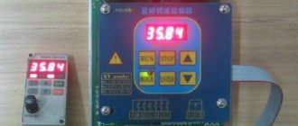
Angle grinder (grinder) BOSCH GWS 9-125 S with speed control. Photo 220Volt
The grinder in its classic version already has wide application possibilities . Equipping with additional options further increases its functionality , making working with it more comfortable and safe. The most common are soft start devices, support for constant speed under load, protection against vibration and accidental starting, and rotation speed adjustment . If the grinder does not have such capabilities, the user can install them independently . For example, some users use a speed control unit to modify angle grinders on which the manufacturer did not install it.
Usage
There are a number of recommendations for the correct use of an angle grinder with an electronic unit.
When starting the tool, let it accelerate to the set speed, do not rush to cut anything. After turning off, restart it after a few seconds so that the capacitors in the circuit have time to discharge, then the restart will be smooth. You can adjust the speed while the grinder is operating by slowly turning the variable resistor knob. The good thing about a grinder without a speed controller is that without serious expenses you can make a universal speed controller for any power tool yourself. The electronic unit, mounted in a separate box, and not in the body of the grinding machine, can be used for a drill, drill, or circular saw. For any tool with a commutator motor. Of course, it’s more convenient when the control knob is on the instrument, and you don’t have to go anywhere or bend over to turn it. But here it’s up to you to decide. It's a matter of taste.
If you have an old grinder among your tools, do not rush to get rid of it. Using a simple electrical circuit, the tool can be improved by adding the option of adjusting the rotation speed. Thanks to a conventional control device, which you can create with your own hands within a few hours, the functions of the tool will expand significantly. By reducing the number of rotations per unit of time, the angle grinder can be used as a sharpening and grinding unit for different types of materials. There will be additional opportunities for using auxiliary equipment and attachments.
The main malfunctions of an angle grinder and their causes
According to statistics, most cases of angle grinder failure are associated with the electrical part of the device. Some damage may be minor, which allows you to repair the angle grinder yourself. But, for example, if the motor windings burn out, only a specialist can repair an angle grinder.
Grinder won't turn on
The reasons that the angle grinder does not turn on may be the following:
- the electrical plug is faulty;
- the electrical cable is faulty;
- the start button is broken;
- the contact between the power cable and the button is broken;
- break in the contact wire of the electric brush;
- severe wear of electric brushes;
- failure of the rotor or stator windings.
The angle grinder does not develop speed
The reasons why the angle grinder does not gain momentum can be different.
- Damage to the speed control unit. To check this version, you need to connect the device’s motor directly, bypassing the regulator, and check the operation of the device.
- Failure of the electrical cable due to constant kinks or mechanical damage. Because of this, the damaged wire begins to heat up under load, and engine speed drops.
- Collector contamination with dust. Contaminants must be removed with alcohol.
- Problems with brushes. They may be worn out or have a short contact wire as shown in the following photo.
Although the brush is half worn out, it is still fully functional. In this case, a short contact wire prevents the spring from pressing the electrode to the collector. This situation may also be the reason why the angle grinder stopped working normally.
The electric motor is heating up
The reasons why the angle grinder is heating up may be the following.
- Incorrect operating mode of the device. As a result of overloads, the electric motor can become very hot, which often leads to burnout of the windings.
- Destruction of bearings located on the armature. As a result, the rotor clings to the stator, engine operation becomes difficult, and the windings overheat. The problem is solved by replacing the bearings.
- Clogged ventilation ducts through which air flows to cool the engine. The ventilation openings must be cleared of dust.
- Damage to the impeller used to cool the engine. It is installed on the rotor, on the side opposite to the collector. If the impeller is broken, it must be replaced with a new one.
- Interturn short circuits of stator and rotor windings. It will be necessary to rewind the reels or replace these parts with new ones.
Bulgarian sparkles
If you notice strong sparking when you turn on the angle grinder in the place where the collector is located, then the reasons for this trouble may be the following.
- Damage to the armature winding: break of one or more sections of the winding, interturn short circuit. With such breakdowns, increased noise appears, engine speed drops and brushes burn.
- The contact between the collector plates and the winding is broken.
- Weak brush pressure. During long-term operation of the angle grinder, the springs overheat and can “anneal”, thereby losing their elasticity.
- Engine rotor imbalance.
- Damage to the cylindrical surface of the collector. This sometimes happens after rewinding, if the armature is not turned on a lathe, but is immediately installed in the machine. In this case, you can also observe that the brushes spark excessively.
- The insulation between the collector lamellas is broken. There may also be clogging of the track grooves with graphite or a breakdown between the lamellas.
- Bearing wear, which causes the rotor to run out, also causes the brushes to spark heavily.
- Violation of the geometry of the armature shaft. This usually happens when the electric motor is disassembled carelessly and the shaft bends.
- Wrong brand of graphite brushes installed. Brushes are selected based on the expected speed and voltage.
- Raising one or more lamellas causes the brushes to quickly burn out. This happens due to engine overheating during prolonged operation. As a result, the glass melt, which serves as the basis of the collector, softens and the lamellas begin to rise. Due to the fact that the slats are raised, the brushes wear out very quickly.
Why control the speed of the disk?
If the grinder is used for cutting and cutting tiles and natural stone products, the high rotation speed of the tool literally kills the power tool. In addition, with such processing, small particles begin to crumble from the material. This significantly deteriorates the quality and appearance of the tiled or stone surface. If there is a function for selecting the required speed, processing proceeds without a hitch. And the electric tool itself is completely protected from damage.
When cutting tiles and stone products, the grinder operates at a very high rotation speed
Rotation speed is also important when working with metal products. For example, aluminum or tin blanks should be cut at minimum speed. But thick and hard metal, on the contrary, is processed at high speeds. Polishing and grinding work using an angle grinder cannot be performed effectively if the saw does not allow you to select the required speed. You will simply ruin the surface being treated. Try sanding wood or the paintwork of a car body at high speed and you will understand what we are talking about.
As you can see, modifications to the angle grinder make the device many times more functional. It becomes possible to work with any soft materials and delicate surfaces. And most importantly, the grinder becomes almost eternal. It will function for decades!
Advantages of universal angle grinders
Angle grinder (grinder) METABO WEV 10-125 Quick 600388000 (in box). Photo 220Volt
It is not always possible to solve the problem of processing certain types of materials with an ordinary angle grinder without additional options; the working tool is not suitable for effective work at the speeds produced by an angle grinder without a speed controller. The problem of choosing the right modes is especially acute for users involved in grinding, cleaning, and polishing various materials. To complete the job, sometimes you have to look for another tool with suitable characteristics.
The versatility of angle grinders with variable speed control lies precisely in the ability to independently set the rotation speed of, for example, cord brushes when stripping. When performing grinding operations, the contact patch between the working tool and the surface being processed increases, which requires the use of high-power grinders. Such grinders with additional options installed on them perform almost any type of work with various materials.
Subtleties of work
If the regulator is assembled correctly and configured, then turning on the tool will be convenient at low speeds, when there is no jerk. During operation, especially considering the increased danger of angle grinders, it is necessary to make sure that accidental impact on the regulator handle is impossible
This is especially important if the regulator is built into the cord, not far from the body of the grinder itself.
If before this the machine did not have a regulator, then you need to keep in mind that this regulator will tend to maintain speeds close to idle under load, so there is no need to particularly accelerate the angle grinder under a heavy load. When the resistance of the material being processed brakes the disc, the voltage at the current sensor increases due to the increase in current, and the voltage at the motor drops slightly. The microcircuit reacts to this by changing the angle (the moment of unlocking the triac) in the direction of increasing power.
If the current is too high, the protection is triggered and the angle changes in the direction of decreasing power. So you may have to select R9 through experimentation, changing the calculated resistance within small limits.
Why does the grinder need low speeds?
The built-in disc speed control function allows you to delicately process materials such as plastic or wood. At low speeds, operating comfort and safety increases. This function is especially useful in electrical and radio installation practice, in car services and restoration workshops.
In addition, among professional users of power tools there is a strong opinion that the simpler the device is, the more reliable it is. And it is better to move the additional service stuffing outside the power unit. In this situation, equipment repair is greatly simplified. Therefore, some companies specially produce remote, separate electronic regulators that connect to the machine’s power cord.
Principle of operation
For assembly, it is best to choose a thyristor converter; it will allow you to change the operating mode without significant losses.
In addition, thanks to it, functions such as:
- Acceleration-braking.
- Tight control of characteristics.
- Switching to reverse movement.
In addition, it has pulse-phase control. Which allows you not to lose rotor torque without increasing losses in the reactive characteristic.
The speed controller circuit will consist of the following key components:
- Controlled signal rectifier.
- Control unit.
- Feedback system.
- Network power regulator.
Electronic unit in an angle grinder
The electronic unit allows you to combine the speed controller and soft start into one. The electronic circuit is implemented on the principle of pulse-phase control with a gradual increase in the opening phase of the triac. Grinders of different power and price categories can be equipped with such a block.
Types of devices with an electronic unit: examples in the table
| Name | Power, W | Maximum disk rotation speed, rpm | Weight, kg | price, rub. |
| Felisatti AG125/1000S | 1000 | 11000 | 2,5 | 2649 |
| Bosch GWS 850 CE | 850 | 11000 | 1,9 | 5190 |
| Makita SA5040C | 1400 | 7800 | 2,4 | 9229 |
| Makita PC5001C | 1400 | 10000 | 5,1 | 43560 |
| Flex LST 803 VR | 1800 | 2400 | 6,5 | 91058 |
Angle grinders with an electronic unit: popular in the photo
Bosch GWS 850 CE
Flex LST 803 VR
How to connect the device to an angle grinder, options
The connection of the regulator depends on what type of device is selected. If a simple circuit is used, it is enough to mount it into the power supply channel of the power tool.
Installing a homemade board
There are no ready-made installation recipes. Anyone who decides to equip an angle grinder with a regulator places it in accordance with their goals and model of the tool. Some people insert the device into the handle of the holder, others into a special additional box on the body.
In different models, the space inside the angle grinder body may be different. Some have enough free space to install a control unit. In others, you have to take it to the surface and attach it in a different way. But the trick is that, as a rule, there is always a certain cavity in the back of the instrument. It is designed for air circulation and cooling.
Cavity at the back of the device
This is usually where the factory speed controller is located. A DIY diagram can be placed in this space. To prevent the regulator from burning out, the thyristors should be installed on the radiator.
Features of installation of the finished block
When purchasing and installing a factory regulator inside an angle grinder, most often you have to modify the body - cut a hole in it to allow the adjustment wheel to come out. But this may adversely affect the rigidity of the casing. Therefore, it is preferable to install the device outside.
The adjustment wheel changes the speed
The numbers on the adjustment wheel indicate the number of spindle revolutions. This value is not absolute, but conditional. “1” is the minimum speed, “9” is the maximum. The remaining numbers serve as a guide for regulation. The location of the wheel on the body varies. For example, on the Bosch PWS 1300–125 CE, Wortex AG 1213–1 E or Watt WWS-900 angle grinders, it is located at the base of the handle. On other models, such as the Makita 9565 CVL, the adjustment wheel is located at the end of the housing.
The connection diagram of the regulator to the angle grinder is not complicated, but sometimes it is not so easy to stretch the cables to the button, which is located at the other end of the device body. The problem can be solved by selecting the optimal wire cross-section or by placing it on the surface of the casing.
The regulator is connected according to the diagram
A good option is to install the regulator on the surface of the device or attach it to a network cable. Not everything always works out on the first try; sometimes the device has to be tested and then some adjustments made. And this is easier to do when access to its elements is open.
Attaching to the power cord
How to make adjustments for an angle grinder at home, homemade options
Some users who have experience working with electrical technologies can make a relatively simple adjustment circuit on semiconductor devices on their own. However, it will not be able to effectively adjust the current strength as the speed decreases, and the amount of torque on the operating shaft may be insufficient. This will not be a big obstacle when carrying out work on polishing, cutting thin sheet metal or processing soft materials (plastic and the like).
If making a circuit with your own hands causes difficulties or the nature of work with an angle grinder, for example with stone or ceramics, requires the use of a more complex system with a microcircuit, it is possible to purchase a ready-made block and install it on an angle grinder.
The authors of the videos presented below offer their approaches to the decision to equip an angle grinder with speed control.
A standard dimmer for changing the brightness of lighting is used in the operation of an angle grinder in the following video.
Important: the power of the dimmer must be at least not less than the power of the angle grinder. The quality of polishing work and the smaller amount of dust emitted during it determine the feasibility of modifying the electrical part of the angle grinder using a standard dimmer
This design requires a reasonable dosage of manual load when carrying out work, since overheating of the engine cannot be ruled out and there is a risk of its failure.
The speed of some electric tools can be controlled not only manually using a rotary wheel. Some devices are more convenient to control using pedals. In the following video, the author demonstrates this method of control. Here, a speed controller made in the form of a pedal from a sewing machine is taken and adapted to control an electric jigsaw. There is nothing stopping you from making this option for controlling the angle grinder, but the need for this must be justified by the nature of the work being carried out.
No power loss
It is almost impossible to make a regulator that changes the speed without losing power. Such devices with feedback for monitoring the speed value and adjusting the current strength based on them are produced only by manufacturers of angle grinders. You can only make or install regulators on semiconductor circuits yourself, which do not guarantee 100% power conservation when changing the rotation speed of the angle grinder spindle.
How to reduce/increase disk rotation speed
A ready-made, inexpensive Chinese-made board can be mounted, as the author of the following video did, in a separate plastic case connected to a cable with a plug and a socket installed on it. By connecting the plug to the electrical network, and the angle grinder to it through the socket, you can change the value of the variable resistance with the adjusting wheel and set the required speed on the angle grinder. Surface polishing with such a power tool will be much better.
How to install, connect
Users of grinders have come up with many different ways to arrange the speed controller and the grinder for which it is intended. It can be located as a stand-alone element outside the body of the angle grinder, or built inside. Below are videos with these options.
In the following video, the author uses a carrying device with an on/off button as an external control device. Just instead of this very button, a ready-made Chinese semiconductor board is inserted. The technology of electrical installation work was performed at a good technical level. This type of carrier will be convenient to use when using an angle grinder for work that requires the use of low speeds.
Placing additional devices inside the body of an angle grinder can be quite a difficult problem. Often non-trivial decisions need to be made, such as in the following video. Here, in order to place a board with speed control and soft start, we had to change the buttons involved in the operation of the on/off lever. In the freed space we managed to place a triac with a radiator for cooling the speed controller and a board with a soft-start microcircuit for the grinder.
How to disable or remove the voltage sensor
In the following video, the author’s speed controller failed on one of the angle grinder models. Attempts to repair it were unsuccessful. The author describes how you can remove a broken regulator and assemble an electrical circuit without it (just connect the stator windings directly through a switch). The grinder will function only at maximum speed.
Device Instruction Manual
The basic rule when operating an angle grinder with a homemade speed controller is to adhere to the work and rest schedule. The fact is that an engine operating at a “regulated” voltage gets especially hot
When grinding at low speeds, it is important to take frequent breaks so that the commutator windings do not burn out.
It is also highly recommended not to turn on the tool if the speed controller is set to minimum - the reduced voltage will not be enough to rotate the rotor, the collector lamellas will remain in short circuit mode, and the windings will begin to overheat. Unscrew the variable resistor to the maximum, then, turning on the angle grinder, reduce the speed to the desired value.
In addition, it should be understood that adjusting the speed of rotation on an angle grinder occurs on the principle of a water tap. The device does not increase the number of revolutions, it can only decrease them. It follows from this that if the maximum nameplate speed is 3000 rpm, then when a speed controller is connected, the angle grinder will operate in a range lower than the maximum speed.
Video: homemade angle grinder speed controller
Equipping the angle grinder with a circuit for adjusting engine speed will increase the efficiency of using the device. and expand its functional range. This will also save the technological resource of the grinding machine and increase its service life.
Types of faults in the electrical and mechanical parts of the drill
DIY motion sensor repair
The most common electrical problems are when the drill sparks at the brushes due to significant grinding or wear. A device with heavily worn brushes will not turn on at all. A sign of problems with the engine is the absence of signs of its activation (sound, vibration, etc.). For a drill with variable speed control, reverse and speed control may no longer function.
Mechanical faults - failure of a bearing or gear mechanism, shaft failure. They are manifested by humming, periodic stops of the device, and slow rotation. Sometimes problems arise with the chuck: difficulties in disconnecting the drill, unscrewing the chuck relative to the shaft.
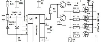
Typical speed controller circuit
This is what the assembled speed controller board looks like
The engine speed controller is not just a variable resistor that lowers the voltage. Electronic control of the current strength is necessary, otherwise, as the speed drops, the power and, accordingly, the torque will decrease proportionally. In the end, a critically low voltage value will occur when, even with the slightest resistance of the disk, the electric motor simply cannot turn the shaft. Therefore, even the simplest regulator must be calculated and implemented in the form of a well-developed circuit.
And more advanced (and therefore expensive) models are equipped with regulators based on an integrated circuit.
Integrated controller circuit. (the most advanced option)
If we consider the electrical circuit of the angle grinder in principle, it consists of a speed controller and a soft start module. Power tools equipped with advanced electronic systems are significantly more expensive than their simpler counterparts. Therefore, not every home craftsman is able to purchase such a model. And without these electronic units, all that remains is the electric motor winding and the power button.
The reliability of modern electronic components of angle grinders exceeds the service life of motor windings, so you should not be afraid of purchasing a power tool equipped with such devices. The only limiting factor can be the price of the product. Moreover, users of inexpensive models without a regulator sooner or later come to install it themselves. The block can be purchased ready-made or made independently.
Electrical equipment for an angle grinder
Over 40 years, the appearance of the angle grinder has remained virtually unchanged: an oblong body with a motor and gearbox mounted inside, a handle screwed to the side and a protective casing.
A grinder, like any tool, sooner or later refuses to work. But there are situations when a simple repair of electrical equipment is sufficient to eliminate a malfunction. To perform these minor repairs, you need to have an understanding of how such equipment works internally and be able to read its electrical diagram.
The electrical circuit of the grinding machine consists of the following elements:
Why do you need to adjust the speed on an angle grinder?
Any grinder is structurally “sharpened” to work only with a cutting or grinding wheel of a certain diameter. In total, there are six most common diameters in the range from 115 to 300 mm, which correspond to six groups of spindle rotation speeds at idle. For example, grinders with Ø125 mm wheels have a rotation speed of about 11÷12 thousand rpm, and with Ø150 mm wheels - 9÷10 thousand rpm. Such spindle speed values are due to the fact that cutting discs are designed for high-performance processing of hard materials (metal, stone, ceramics) at cutting speeds of up to 80 m/sec.
However, when cutting and especially grinding soft and viscous materials, completely different cutting parameters are required and, accordingly, the use of a tool with a speed controller. Moreover, this applies not only to wood and plastics, but also to steels, titanium and aluminum alloys. For example, processing of plastics and soft woods occurs at cutting speeds from 8 to 12 m/sec, grinding of titanium and stainless steel alloys - within 15÷20 m/sec, and even ordinary steel is ground at no more than 30 m/sec. Therefore, the rotation speed of grinding attachments for grinders should be several times less than the rated speed. It should be noted that for the most part, angle grinder speed controllers are essentially regulators of the power supplied to the electric motor of the angle grinder. That is, a reduction in the speed is achieved by reducing the source power by up to 15% of the nominal. But for grinding and cutting soft materials this does not matter much, since in this case little power is initially required.
What it is?
Grinders with a speed controller use commutator motors with sequential excitation.
They can operate on direct or alternating current. This type of motor is easily controlled by changing the current in the circuit. Due to the fact that modern regulators use key pulse control, they heat up very little and can be built into the body of even a small-sized instrument. For regulation, a potentiometer is used, the handle of which is located on the handle of the machine.
Why control the speed of the disk?
Different cutting or grinding speeds are required according to the physical properties of the materials being worked with. Thus, high speed with low pressure is required when cutting hard materials that might otherwise crumble or splinter. Soft materials that are not resistant to heat (thermoplastics, wood), on the contrary, require low speed:
- ceramics: 10000 rpm;
- metal: 8000 rpm;
- hard plastics: 5000 – 8000 rpm;
- wood: 3000 – 5000 rpm;
- soft plastics: less than 2000 rpm.
All professional tools are equipped with a stabilized speed controller, but inexpensive household angle grinders with a power of less than 1200 W are not always supplemented with it. In this article we will talk about how to make such a regulator yourself to reduce the speed.
Speed controller and soft start - what are they for?
Modern grinders use two important functions that increase the reliability and safety of the tool:
- speed controller - a device designed to change the number of engine revolutions in various operating modes;
- soft start - a circuit that ensures a slow increase in engine speed from zero to maximum when the device is turned on.
They are used in electromechanical tools that use a commutator motor in their design. Helps reduce wear on the mechanical part of the unit during switching on. They reduce the load on the electrical elements of the mechanism by putting them into operation gradually.
When the power is turned on, an abrupt transition occurs from a state of rest to rotation of the disk at a speed of 2.5–10 thousand revolutions per minute. Those who have worked with an angle grinder are well aware of the feeling that the machine simply “rips out of your hands.” It is at this moment that the overwhelming number of breakdowns associated with the mechanical part of the unit occur.
The stator and rotor windings experience no less load. The commutator motor starts in short circuit mode, the electromotive force is already pushing the shaft forward, but inertia does not yet allow it to rotate. A jump in starting current occurs in the coils of the electric motor. And although they are structurally designed for such work, sooner or later a moment comes (for example, during a power surge in the network) when the winding insulation cannot withstand and an interturn short circuit occurs.
When soft start circuits and changes in engine speed are included in the electrical circuit of the tool, all of the above problems automatically disappear. Among other things, the problem of voltage “dip” in the general network at the moment of starting a hand tool is solved. This means that the refrigerator, TV or computer will not be at risk of “burning out”. And the safety circuit breakers on the meter will not operate and cut off the current in the house or apartment.
The soft start circuit is used in angle grinders of medium and high price categories, the speed control unit is used mainly in professional models of angle grinders.
Additional electrical circuits increase the cost of the tool, but increase the service life and level of safety during operation.
Making a speed controller
An electric angle grinder is impossible without a speed controller, so that it is possible to reduce the speed.
The regulator circuit from a physics point of view looks like this
- Resistor – R1;
- Trimmer resistor – VR1;
- Capacitor – C10;
- Triac - DIAC;
- Triac - TRIAC.
The electronic regulator can be not only built-in, but also remote for convenience. In Bosch angle grinders, the electronics set the speed from almost 3 thousand to 11.5 thousand. There is no load on the meter's power, all indicators are taken into account. Reducing the number of revolutions and increasing them is not difficult for the tool. Adjustable rotation speeds are simply necessary when working with an angle grinder.
Photo of the speed controller with your own hands
Screwdriver speed controller
An electric screwdriver operates either from a 220 V network or from a rechargeable battery. Its power depends on the battery voltage. The screwdriver rotation speed starts at 15,000 rpm. In addition, a powered screwdriver has 2 rotation speeds: a slower one for screwing, a higher one for drilling. The speed control is located inside the power button. The rather miniature size of this tool assembly is achieved using microfilm technology. Its main part is a triac. The operating principle of the regulator is as follows:
- When the button is turned on, an alternating current having a sinusoidal phase is supplied to the control electrode of the triac.
- The triac opens and current begins to pass through the load.
The response time of the triac depends on the amplitude of the control voltage. The greater the amplitude, the earlier the triac is triggered. The amplitude value is set using a variable resistor connected to the start button. The button connection diagram differs in different models. It is possible to connect a capacitor to the speed controller.
Often, in the current economic conditions, the buyer cannot always afford a full-fledged expensive screwdriver from reputable companies. Cheaper models may not have this feature. But this is no reason to despair. You can assemble the speed controller yourself, which we will talk about below.
The screwdriver speed controller is assembled on the basis of a PWM controller and a key multi-channel field-effect transistor. The operation of this tool unit is controlled by a resistor. Its position depends on the pressure on the screwdriver start button.
The direction of rotation of the working body changes by changing the poles of the voltage that is supplied to the motor brushes. This is done instrumentally using changeover contacts actuated by a reverse lever.
It is possible to assemble such a regulator with your own hands. We will look at how to do this below.
A diagram of the elements that make up the speed controller is shown in the figure below.
Scheme
In this case, a dual comparator microcircuit LM 393 is used. Here, the first comparator works as a sawtooth voltage generator, and the second one is PWM. The control signal for PWM is the voltage drop across the motor contacts. To put it simply, in the diagram the electric motor looks like active and inductive resistances connected in series with each other. When the load changes, the ratio of these resistances changes accordingly, the regulator controls this and changes the PWM filling, thereby stabilizing the speed.
An electronic transformer should be used as the power source for PWM. It is a half-bridge voltage converter from 220 to 12 V, which is used to power halogen lighting lamps. Its dimensions are comparable to the size of a matchbox. The price fluctuates between 2–3 USD. e. It is necessary to add a rectifier to the output (these are four diodes, for example, KD 213), as well as a capacitor with a capacity of several thousand microfarads at 25 volts. All this will constitute a switching power supply with a constant output voltage.
We should also talk about making a printed circuit board for the regulator. To make it you need a sheet of photo paper and a laser printer. First you need to print the design on photo paper using a laser printer, then transfer it to the board blank using a heated iron. The board blank with the paper attached is placed in a container and placed under a stream of hot water. This is done so that the gelatin layer of the photo paper swells and it peels off from the board. The remaining pattern on the board is etched with ferric chloride.
How to assemble an adjustment circuit?
The traditional speed control circuit is quite simple: phase-pulse triggering of a triac, there are only a few parts in it. However, it does not behave very stably, so a professional tool uses this principle in a complicated version, with feedback and overcurrent protection (U2008B and U2010B microcircuits).
Now more advanced options are appearing, using PWM controllers. Their circuits are a little more complicated, but the main difficulties arise during setup and assembly. You may need instruments costing tens of thousands of rubles (oscilloscope), and the ability to work with expensive parts that are afraid of static charges. In general, this is not for ordinary consumers.
Therefore, it is better to take an average solution: a version with a triac and a U2008 microcircuit; this circuit will only require proper assembly and inexpensive parts. It's a simple device, but for a household tool it works just fine.
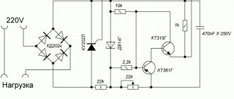
Electrical circuit diagram
The schematic diagram is shown in the figure below:
Most of the parts used in the circuit: MLT-0.25 resistors, K73-17 capacitors.
ATTENTION! Resistor R2, regardless of its design, must have a well-insulated handle. It has a direct connection to the power supply network.
Capacitor C4 type K50-35 for a voltage of 50 V. It should be taken into account that a negative voltage is applied to pin 5 of the D1 chip. Usually in circuits the common wire is a minus, but here it is a plus. Resistor R5 MLT-0.5, R7 - it is better to use a multi-turn film resistor. Diode D1 can be taken KD105B, V or similar. Resistor R8 is MLT-2, a noticeable power drop will occur on it. Resistor R9 is discussed next.
Circuit operation
The U2008B microcircuit is a voltage-stabilized phase regulator. It offers a choice between a soft start function and speed stabilization. Pin 1 is supplied with a signal from a current sensor or, if a soft start is used, an electrolytic capacitor with a capacity of several microfarads is connected.
Creating a regulator yourself
How to make your own regulator? The attempt to install an ordinary electronic device designed to change electrical power (dimmer) ends in nothing. First of all, the dimmer for an angle grinder is designed for a different load. Also, the dimmer is not combined with the control of the electric motor winding. Therefore, it is necessary to install a separate circuit. You also need to figure out where it will be located inside the body of the angle grinder.
You can build a simple semiconductor device (thyristor regulator) with your own hands. For this procedure you will need 5 radioelements. Radio elements can be bought on the radio market. Thanks to its compactness, you can safely place the prepared circuit in an angle grinder without damaging ergonomics and reliability. However, torque conservation does not occur when the speed of the grinder is reduced. This option is best suited for processing soft metals, as well as thin sheet metal.
If you are processing stone, then you need to install a disk that has a size of 180 millimeters. Next you need to create a more complicated regulator circuit. In this circuit, the control module will be the KR1182PM1 microcircuit. This circuit has control over the current strength at different speeds, and also makes the loss of torque minimal as the speed decreases. When using this scheme, engine operation increases.
If the angle grinder is used as a circular grinder, then you need to equip the angle grinder with a connection point. Thanks to this point, the connection is made, and the speed can be adjusted remotely. You will have an excellent homemade speed controller.
It does not depend on how you made the regulator, but it is an essential component of an angle grinder, which makes the work possibilities wider and allows you to comfortably use this construction tool. Also, after installing the regulator, it is necessary to conduct a test run of the angle grinder to check whether the construction tool is pulled out of your hands. You can make an external speed controller for an angle grinder yourself.
What is this function, principle of operation, electrical circuit, advantages of an angle grinder with a regulator
Most models of grinders do not have a built-in speed controller, like on vacuum cleaners. Such devices operate only at maximum rotation speed. However, if you build a special regulator into them, a person will be able to reduce the speed to such a level that it is possible to process this or that material more efficiently.
For what purpose does an angle grinder have low speeds?
Many people are interested in why they need to adjust the speed on an angle grinder. Most often, people decide to reduce the rotation speed of the wheel in order to process plastic or wood more gently.
Also, at a reduced speed, the safety of using such power tools increases. The fact is that at low speeds the angle grinder vibrates less and sits much better in the hand.
Why does an angle grinder need a soft start and a speed controller?
Rotation regulator - allows you to independently set the speed while using the power tool.
Modern models of angle grinders use two technologies that increase the safety and performance of the power tool:
- Rotation speed regulator. This device is installed so that a person can switch the operating modes of the motor.
- Smooth start. Most often, this function is found in expensive models from Dimmer. When using a smooth descent, the motor operation will gradually increase from zero to the maximum value.
The above technologies are very useful. The fact is that with their help it is possible to reduce the wear of the tool and increase its service life. Therefore, people who decide to buy a grinder are recommended to look for models with a built-in smooth release and rotation regulator.
Connection diagram without power regulator
Connection diagram - may be needed when connecting the power tuning module
People who decide to independently connect the device to adjust the speed should familiarize themselves with the grinder diagram in advance. This will help you understand how everything works in it.
The main element of the entire circuit is the stator. It has two interconnected windings. They are connected to the voltage source through a separate switch. It is in it that the start button is installed, which is responsible for starting the grinder’s operation.
Each of the existing windings is connected to graphite brushes using special contacts that are securely connected to the commutator surface. In this case, the ends of the winding are connected to the collector lamellas. The result is a closed electrical circuit.