Due to the peculiarities of their design, groove cutters (also called slotting cutters) are considered multifunctional tools that can be used to form grooves on workpieces of cylindrical and conical configurations. Such technological operations (especially those associated with radial grooving) are characterized by significant loads, which are successfully carried by a cutter of this type, characterized by high structural rigidity. Moreover, groove cutters are successfully used for axial grooving and facing, making them versatile turning tools.
Grooving cutters for internal and external grooves with mechanical fastening of replaceable cutting inserts
It is advisable to use groove turning tools to obtain parts with complex configurations. The versatility of cutters of this type in such cases allows us to minimize the number of tools used and reduce the time for equipment changeover. It is also noteworthy that the use of a groove cutter when performing many technological operations makes it possible to form surfaces with higher quality characteristics than when using a conventional turning tool.
Particularly successful is the use of a groove cutter when creating wide grooves on the surface of workpieces. When performing this technological operation, such a tool demonstrates exceptional durability; wear of its cutting plate occurs evenly even when performing a large number of passes. What is also important is that when using a groove cutter, the chip separation process is well controlled.
Requirements for groove-type cutters, which are produced in a wide variety of standard sizes, are specified by the provisions of GOST 18874-73.
Geometric parameters and tool dimensions
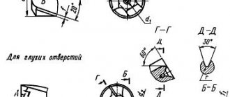
The design of any groove cutter is characterized by its geometric parameters.
- Geometry of the body or holder: L – length of the body, B and H – dimensions of the cross-sectional sides.
- Location of the cutting element in the body. The socket for the plate can occupy the entire width of the case or one of the corners. In the latter case, the width of the socket is indicated by the letter n. The plate can be placed in the socket at a certain angle to the body.
Shape of the working cutting plate: l – length of the working part of the cutter, b – height of the plate body, S – thickness.
The blade for cutting the workpiece also has its own parameters, expressed in angles.
- “Gamma” displays the front sharpening angle - this is the main element of the cutting edge.
- “Alpha” is the rear main sharpening angle.
- “Alpha” with index 1 is the rear corner for auxiliary purposes.
- "Lambda" is the angle at which the cutting edge is inclined.
- “Phi” is the main purpose angle located in plan.
- “Phi” with index 1 is an auxiliary angle located in plan.
Damn.3
Type 3
______________
* At a length not less than the thread pitch.
Damn.3
Table 5
Dimensions in mm
| Cutter section | Designation of plates according to GOST 25422-90, GOST 25412-90 | |||||||
| 0,60 | 11,3 | 0,75 | 48010 | |||||
| 0,96 | 1,00 | |||||||
| 20x12 | 1,33 | 15,3 | 1,25 | 18,0 | 48030 | |||
| 1,56 | 1,75 | |||||||
| 25x16 | 0,25 | 1,93 | 16,9 | 2,00 | 22,0 | 48050 | ||
| 2,67 | 2,50 | |||||||
| 13,0 | 3,39 | 18,9 | 3,00 | 29,0 | 48090 | |||
| 32x20 | 4,12 | 3,50 | ||||||
| 18,0 | 5,32 | 23,7 | 5,00 | 28,5 | 48130 | |||
| 40x25 | 0,50 | 22,0 | 6,78 | 10,0 | 30,7 | 6,00 | 37,0 | 32230 |
| 28,0 | 8,24 | 12,0 | 34,7 | 7,00 | 32250 |
Markings used
The designation of groove cutters is encoded, which provides a complete definition of the geometric parameters of the tool included in the tables of regulatory documents. The main product markings mention parameters such as the alloy with the percentage of metal components in the alloy. For example, if you take a T5K10 cutter, then there will be an alloy based on the titanium-tungsten group, where titanium carbide is up to 5%, and cobalt is up to 10%.
To select cutting groove products, it is not enough to know only the composition of the alloy; you need to proceed from all the parameters specified by GOST.
Damn.2
Type 2
_______________
* At a length not less than the thread pitch.
Damn.2
Table 3
Dimensions in mm
| Cutter section | Designation of plates according to GOST 25398-90 | |||
| 10x10 | 11150 | |||
| 12x12 | 10,5 | |||
| 16x16 | 13,5 | 11190 | ||
| 20x20 | 12,5 | 11,5 | 17,5 | 11210 |
| 25x25 | 16,0 | 15,0 | 22,0 | 11230 |
Table 4
mm
| Thread pitch | 0,75 | 0,80 | 1,00 | 1,25 | 1,50 | 1,75 | 2,00 | 2,50 | 3,00 | 3,50 | 4,00 | 4,50 | 5,00 | 5,50 | 6,00 |
| 0,050 | 0,055 | 0,072 | 0,090 | 0,110 | 0,125 | 0,145 | 0,18 | 0,215 | 0,250 | 0,288 | 0,325 | 0,360 | 0,400 | 0,430 |
GOST standards for groove cutters
Regulatory documents have been developed for groove cutters of various modifications:
- GOST 18874-73 regulates the standards for cutting and slotting equipment, which specifies the dimensions and design of the tool, which is made of high-speed steel.
- GOST 18885-73 describes the design features of groove cutters for thread production, which are equipped with carbide plates.
- GOST 18884 - 73 - this normative act gives instructions on the size and design of cutting tools for turning, the plates of which are tipped with carbide alloys.
- GOST 28978-91 - the document defines the standard for prefabricated groove cutting tools.
Damn.1
Type 1
_______________
* At a length not less than the thread pitch.
Damn.1
Table 1
Dimensions in mm
| Cutter section | Designation of plates according to GOST 25398-90 | |||
| 16x10 | 13,5 | 15,5 | 11130 | |
| 20x12 | 15,0 | 16,0 | 19,0 | 11190 |
| 25x16 | 18,6 | 20,0 | 22,5 | 11210 |
| 32x20 | 23,3 | 26,0 | 29,0 | 11230 |
table 2
mm
| Thread pitch | 0,50 | 0,75 | 0,80 | 1,00 | 1,25 | 1,50 | 1,75 | 2,00 | 2,50 | 3,00 | 3,50 | 4,00 | 4,50 | 5,00 | 5,50 | 6,00 |
| 0,072 | 0,108 | 0,115 | 0,144 | 0,180 | 0,216 | 0,252 | 0,288 | 0,360 | 0,432 | 0,504 | 0,576 | 0,648 | 0,720 | 0,792 | 0,870 | |
| 0,047 | 0,079 | 0,085 | 0,113 | 0,146 | 0,179 | 0,213 | 0,249 | 0,317 | 0,389 | 0,459 | 0,529 | 0,601 | 0,670 | 0,742 | 0,812 |
Recommendations for selecting groove cutters
When choosing a groove cutter, you should be guided by the following considerations:
- First of all, they analyze the drawing according to which the part will be manufactured. The drawing shows all the parameters of the grooves: width, depth, shape, as well as standards for manufacturing accuracy and possible tolerances.
- The metal from which the part is made. For carbide metals, appropriate cutters with a carbide blade are used; for soft metals, ordinary grooved ones are used.
- When choosing a tool for cutting grooves inside a hole, the diameter of the holder and the size of the protruding edge of the knife are important. Here, too, it is more advisable to use carbide equipment.
- Equipment for carrying out operations. The choice of groove cutter is determined in this case depending on the possible operating modes of the machine, the configuration and type of tool holder.
- Features of the technological process. The technical process can affect the processing speed of the product. The higher the speed, the stronger and more durable the grooving equipment must be used to achieve processing goals.
- Is there any provision for lubrication of the treatment area during the operation? Lubrication has a positive effect on the work, removing part of the load from the groove tool and thereby making it possible to use simpler equipment.
Geometry and dimensions of groove type cutters
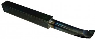
Since groove-type cutters experience significant load during processing, which determines increased requirements for their rigidity, they are manufactured with soldered carbide plates, the characteristics of which are specified in GOST 2209-82. The requirements for the cutter itself, as stated above, are given in GOST 18874-73.
The main feature of the geometry of groove-type cutters is that the shape of their cutting part must exactly match the shape of the groove that is planned to be obtained with their help. The grooves created on the surface of the workpiece are usually small in width. Accordingly, the cutting part of the tool with which they are formed is also quite narrow, which makes it very vulnerable to mechanical damage. In addition, the working head on each side has a narrowing towards the holder (by 1–2 degrees). Such a narrowing of the sides of the cutting part is necessary in order to reduce their friction against the walls of the groove being formed.
Geometric parameters of the groove cutter
To increase the strength of the cutting head of a groove turning tool, its height is made significantly larger than its width. This also requires a small rake angle and a sharpening of the cutting edge with a small radius (curvilinear). The optimal cutting angles for groove-type cutters are 15–250 (front), 8–120 (rear).
The width of the working part of the groove tool, which, according to the requirements of GOST 18874-73, can vary over a wide range, is selected depending on the width of the groove that needs to be formed on the outer or inner surface of the workpiece.
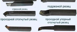
What is a metal lathe cutter?
This tool is a product whose elements carry out turning of metal workpieces on metalworking equipment. The cutter design contains:
- Holder. This element is necessary to fix the product. The cross section can be square or rectangular.
- Working head. It processes a metal workpiece on a machine. The shape of this cutting element is made from several planes. The work is performed by cutting edges sharpened at a certain angle. Sharpening cutters for a metal lathe depends on the characteristics of the workpiece material and what type of processing is being performed.
Features of turning using a groove cutter
The cutting modes when using groove-type cutters have some differences from the modes of processing the workpiece with other types of turning tools. Thus, the depth of cut is taken to be a value equal to the width of the groove being formed, and the tool feed per revolution of the part is measured in the direction perpendicular to its axis. The feed rate, depending on the material from which the cutting part of the groove tool is made, is selected in the range of 0.07–0.2 mm/rev, and the cutting speed is 15–180 m/min.
Several types of grooves can be obtained on the surface of the workpiece.
- Narrow grooves, the width of which corresponds to the width of the cutting part of the tool, are made in one pass of the cutter, which is fed manually. Before this, the exact location of the groove is determined on the surface of the part, and then the cutter is placed opposite this place and fed.
- The grooves on the ledges and ends of the part are made according to the same principle; their diameter is set using the transverse feed dial, and their depth is set using the longitudinal movement dial of the caliper.
- Wide grooves are made in several passes according to the following scheme. First, determine the location of the right edge of the groove and place the cutter opposite this location. Using a transverse feed, the cutter is cut into the part to a depth that is 0.5 mm less than the depth of the groove being cut (this allowance is left for finishing). Then, using a longitudinal feed, the groove tool begins to move to the left edge of the groove being cut, the boundary of which has been previously marked. After the rough groove is formed, its bottom is processed cleanly - to the required depth, carrying out the longitudinal feed of the cutter from left to right. In the event that it is necessary to form a groove with a very precise location of its left and right edges, allowances can also be left on them during roughing, which are then removed using the transverse feed of a groove or scoring cutter.
Types of work performed by grooving cutters
Main dimensions and materials
A turning groove cutter is generally no longer than 270 mm, the width of the working head varies from 2 to 10 mm, the thickness and height in the case of a rectangular and square section of the rod reaches 50 mm. When working on machines at low speeds, carbon tool steel is used to make cutters, alloyed to speed up operations. At high speeds, high-alloy steel can be used, the speed increases up to one and a half times, the tool can withstand increased temperatures.
Inserts for turning grooves in compound cutters can be made of various materials:
- carbide brazed;
- metal-ceramic based on compounds of cobalt with titanium and tungsten;
- mineral-ceramic, used mainly for processing high-strength parts, resistant to high temperatures, but fragile and expensive;
- diamond, very durable, but burn out at high temperatures;
- CBN, based on boron nitride, maintains temperature well and can process high-strength materials.
Each of the above materials is characterized by application features; when choosing, price is not the main argument - you can buy many cheap ones that cannot replace several expensive ones, but with optimal parameters. Turning groove cutters are an expensive tool; choosing them correctly will save money and will not disrupt the production cycle.
Design
Absolutely all options, from the most common to the very specific, consist of the following two key parts:
- a holder with a strictly defined cross-section, the shape of which is either rectangular or square, for reliable fixation in the equipment;
- a head with several usable planes and edges (each of which will be discussed below) - for direct processing of the material (be it alloy steel, cast iron or some other).
According to geometry, the following execution methods are distinguished:
- straight - both of its above-mentioned components are located either parallel or on the same axis;
- curved - with a slightly noticeable curvature of the profile inward;
- bent - with an obvious bend reaching an almost zigzag shape;
- retracted - the head is narrower in width than the holder and is placed either symmetrically along the axis or offset, to the right or left.
Also, absolutely all types of cutters for lathes that are relevant today can boast of a certain surface geometry, the relative arrangement of which we now move on to.
Planes
There are three:
- The main one is parallel to the reference and, accordingly, to the tool feed vector, which can be located both longitudinally and transversely.
- The cutting plane is perpendicular to the previous one, includes the main edge, and runs tangentially to the workpiece.
- Main secant – passes through the main edge, perpendicular in its role to the projection.
Add here an auxiliary one, which is a secant and is located at an angle of 90 degrees to the corresponding face.
It is important that the dimensions remain within the standard range, that is, do not exceed 160X100 - 630x1000 for rectangular tools and 40X40 - 400X40 for square ones.
Cutter angles
Their parameters depend on the type and conditions of use of the element we are considering, as well as on the hardness of its material and the characteristics of the workpieces being processed. The latter, in turn, determine the sharpness of the head, which means they can be:
- The main ones (according to the placement of planes):
- the front one specifies the degree of deformation upon impact, the efficiency of heat removal, and the applied force; should decrease with increasing hardness of the surface of the part;
- rear - affects the friction force, wear rate, and the quality of the final technological operation.
- sharpening – determines the strength of the equipment;
- cutting – determines the depth of penetration.
- main – sets the quantity and volume of chips to be removed;
- secondary - directly affects the degree of roughness, which decreases proportionally as it decreases.
This is interesting: Chrome plating of plastic at home: technology and tips
Labeling and manufacturers
The description of groove turning tools will be incomplete without mentioning the markings, which determine the composition of the material of their cutting part. For example, the T5K10 cutter is made of a hard alloy of the titanium-tungsten group, which contains 5% titanium carbide and 10% cobalt. The markings of products made from other materials are deciphered in a similar way.
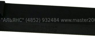
The most famous manufacturers of grooving turning tools are:
- Dnepropetrovsk industrial tools plant (Ukraine);
- (Ukraine);
- Zenitech company (Switzerland);
- Proma company (Czech Republic);
- Itertool company (China).