When performing welding work, it is very important to have high-quality and reliable wire feeding mechanisms on hand. The main advantages are that they make the work easier, since this functionality will ensure the supply of wire to the destination of the welding work.
For semi-automatic welding, such a feeding mechanism will act as a key unit and will simplify the work of even a professional welder. What are the advantages of this mechanism, what modern units exist today for drawing welding wire?
Types of devices
Depending on the method of feeding the welding wire, the mechanism can be:
- pushing;
- pulling;
- combined.
The pushing mechanisms together with the coil are located in the body of the welding machine or as a separate unit. This is the most common execution option.
Through a guide channel, it pushes the filler wire through the torch directly into the welding zone. Thanks to its location, it makes the welder's work easier.
The pulling mechanisms are located in the burner body. This allows you to work with longer guide channels. The disadvantage of this operating principle is the reduction in productivity and efficiency of the welder due to the heavier torch.
Combined devices combine both operating principles, but are extremely rare.
Depending on the thickness of the additive used, the feed mechanisms are two- or four-roller . For wire with a thickness of 1-1.2 mm, a two-roller mechanism with one drive and one clamp is usually used. For additives with a larger cross-section, two rollers of each type are used.
External feed mechanisms can be completely self-contained, portable or stationary. Modern devices are equipped with information panels. They allow you to monitor and adjust equipment parameters.
The device has an electronic control unit, which, if necessary, regulates the feed speed of the welding wire, which varies depending on the technology, working conditions and skills of the welder.
Some models have the ability to memorize welding modes. A cold drawing mode is provided, when the wire is fed into the welding zone without igniting the torch.
It is possible to purge the hose with shielding gas before starting welding work and when it is finished to remove dust and moisture.
Semi-automatic welding
This welding unit is a device with an incomplete automation cycle . The welding process takes place in an inert gas (argon), active gas (carbon dioxide) or a mixture of gases. The principle of welding is that in a semi-automatic machine, an electric arc produced by a direct electric current always burns between the product and the welding wire. During operation, gas passes through the torch to cover the welding zone, creating protection from air exposure. Such semi-automatic machines are good at working with sheet metal.
The semi-automatic machine allows you to significantly reduce operating time and increase the quality of welded joints. The popular model of semi-automatic welding machine MIG MAG works in conjunction with a welding wire pulling mechanism. The device must be located in the welding machine itself in its body or be remote and connected, if necessary, to a power source via a power cable.
The wire wound on a reel must be placed in a semi-automatic spool and then passed through the wire feed mechanism into a special channel. A welding torch is attached to it; gas is supplied from the cylinder to the torch through a specially attached tube. You can also use cored wire and in this case a gas cylinder will not be needed.
Operating principle
An ordinary feed mechanism consists of a DC electric motor, a reduction gear, a pressure and drive roller, a guide and an input channel. In addition, there is a lever with a spring and a screw that acts as a pressure regulator.
When voltage is applied to the electric motor, its shaft begins to rotate at a certain speed. On the same shaft with the electric motor there is a gearbox that reduces the number of revolutions to the required number.
The output shaft of the gearbox rotates the push/pull roller, which in turn pulls the welding wire pressed against it by the second roller. To eliminate slippage, there is an adjusting screw that acts on the pressure spring. It is necessary for a softer and more constant effect on the roller.
The feed mechanism in a semiautomatic welding machine may have a separate adjustment unit, activated from a button on the torch handle. Some models have replaceable bushings on the guide channels.
This allows you to reconfigure the equipment for different wire diameters. In addition, the mechanisms are designed with a valve and fitting for connecting water-cooled burners.
Some four-roller devices have an additional pair of rollers in front of the feed block. Their task is to level the additive. They are usually used when using flux-cored wire with a thickness of 0.8 mm to 4 mm.
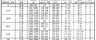
Type and diameter of welding wire
The diameter of the roller groove is selected depending on the diameter and type of welding wire. The diameter and type of wire is written on the product itself - this is an alphanumeric engraving. When changing the wire section, you simply turn the roller over to the desired side and continue to use it further. Please note that the welding wire diameter marking indicates the groove that is closest to the marking.
On the PTK website, in the section about feed rollers, in the configured filters, you can easily select the desired roller by size, type and diameter of welding wire.
Popular models
Lincoln Electric produces a whole line of two- and four-roller mechanisms that feed welding wire. Don't forget about other brands.
LF-37, 38
Models LF-37, LF-38 are designed for use in conditions of high humidity and dust.
They work on 300mm (15kg) spools and can also use 200mm (5kg) spools. The wire can be solid or flux cored. There is a gas flow sensor which is useful when working with long cables. All settings are intuitive, after pressing the “select” button, 2/4 stroke modes are visible, you can adjust the pre-pull before starting work, hot and soft start (Hot/Soft) and crater filling are provided.
You can select the language to display information on the screen. The LF38 mechanism has a set of programs and a memory unit that provides recording of 10 modes of specified parameters.
The device has small dimensions and large indicators that display parameters during the welding process. Connection cables for liquid cooling are available. Can work with wire diameters from 0.6 mm to 1.6 mm. The manufacturer provides a 3-year warranty.
MSF 57
One of the best wire feeders for welding work is the MSF 57 from Kemppi.
The MSF 57 has four rollers. A wire cassette with a diameter of 300 mm is used. The quality of this feed mechanism is at a high level. This is perhaps the most reliable and convenient mechanism on the market based on user feedback.
Model MSF 57 with a power of 100 W is powered by 50 V. The welding wire can be fed into it at a speed of 0 to 25 m per minute.
The mechanism can work with stainless wire with a diameter from 0.6 mm to 1.6 mm, with flux-cored wire from 0.8 mm to 2.0 mm, with aluminum from 1.0 mm to 2.4 mm.
Fast and Furious MPTs02
The Forsage MPTs02 wire feeder from a Russian manufacturer has proven itself well. It has digital control of parameters, adjusts the wire feed speed in the range of 2-20 m/min.
The device has replaceable rollers, which allows you to quickly change to different diameters, and works with coils up to 300 mm. The mechanism provides for adjusting the gas purging time before welding from 0 to 0.5 s, after welding from 0 to 10 s. The gearbox power is 120 W.
Some craftsmen make semi-automatic welding inverters by adding a separate wire feed unit. But for the most part, they are unregulated feed mechanisms whose characteristics are significantly inferior to industrial designs.
When producing a complete analogue of a model, the cost of components will be significantly higher than the finished device.
How to properly thread the wire into the roller?
Correctly threading the welding wire into the feed roller is a guarantee of success when carrying out welding work; it also increases the productivity of semi-automatic welding machines and their service life.
Schematically in the figure we have shown the correct threading of the wire and possible errors that you may encounter.
- Normal clamping force.
- Excessive clamping force.
- Wire diameter too large.
- Wire diameter too small.
When threading the rollers with wire, take into account the recommendations for choosing the clamping force, which is adjusted using the adjusting screw on the feed mechanism of the welding machine.
| Type of welding wire | Clamping force | |
| Steel | 2,5–3,5 | |
| Aluminum | 1–2,5 | |
| Powder | 2–2,5 |
The range of PTK branded products includes a wide selection of feed rollers and related products; you can learn more about the technical characteristics, descriptions and photographs in the product cards. All products are available for order from sales managers and official dealers.
Do-it-yourself semi-automatic welding machine: how to make it, diagram and all the details
A unit designed for welding products is considered to be a semi-automatic welding machine. Such devices can come in various types and shapes. But the most important thing is the inverter mechanism.
It is necessary that it be of high quality, multifunctional and safe for the consumer. Most professional welders do not trust Chinese products and make the devices themselves.
The manufacturing scheme for homemade inverters is quite simple. It is important to consider for what purposes the device will be manufactured.
There are inverters for:
- Welding using flux-cored wire;
- Welding with various gases;
- Welding under a thick layer of flux;
Sometimes, to achieve a high-quality result and obtain an even weld, the interaction of two devices is necessary.
Inverter devices are also divided into:
- Single-hull;
- Double-hull;
- Pushing;
- Pulling;
- Stationary;
- Mobile, which includes a trolley;
- Portable;
- Designed for beginner welders;
- Designed for semi-professional welders;
- Designed for professional craftsmen;
Inverter circuit:
Principle of operation
The operating principle of the inverter includes:
- Adjusting and moving the burner;
- Control and monitoring of the welding process;
When the unit is connected to the electrical network, a conversion of alternating current to direct current is observed. For this procedure you will need an electronic module, special rectifiers and a high-frequency transformer.
For high-quality welding, it is necessary that the future unit has parameters such as the feed speed of the special wire, current strength and voltage in identical balance. For these characteristics, you will need an arc power source that has current-voltage readings.
The length of the arc must be determined by the specified voltage. The wire feed speed directly depends on the welding current.
Homemade device diagram:
The electrical circuit of the device provides for the fact that the type of welding greatly influences the progressive performance of the devices as a whole.
Electrical diagram of a homemade device:
DIY semi-automatic - detailed video
Created plan
Any scheme of a homemade device provides a separate sequence of operation:
Feeding device for the inverter, and how to feed wire into the welding zone
Just 15-20 years ago, working as a welder was labor-intensive and difficult. Welders used large and inconvenient transformers weighing more than 80 kg for their work. The device was equipped with special transportation loops for more convenient movement around the workshop or to the place of welding work. During transportation, special platforms were used. When working at height, it was necessary to feed them with a truck crane. This made the work of the welder and the people around him more difficult.
Inverter
But progress does not stand still and now there are compact inverter welding machines the size of a small box and weighing up to 15 kg. The inverter device works on the principle of rectifying and converting the input network voltage, using special resistors, into a current with a large switching amplitude, then it is reduced to the operating current. The main advantage is that efficiency is achieved up to 90% with small sizes and low weight up to 15 kg. There is also a smooth current setting, which is typical for welding thin metal.
Inverter machines can work both for welding with simple electrodes (MMA) and, together with a feed mechanism, act as a source for semi-automatic welding (MIG).
Nowadays, most inverters support welding modes such as coated electrodes (MMA), refractory tungsten electrodes in argon (TIG), and semi-automatic welding (MAG). They have a welding switch on the control panel, which selects a specific welding method.
Let's take a closer look at what a feed mechanism is and the advantages over welding with simple electrodes.
Feeding mechanism is a set of electromechanical devices that ensure automatic and uninterrupted supply of welding wire and shielding gas to the welding zone.
Feeder
Let's take a closer look at what the feeding mechanism consists of:
- Welding sleeve. It is a flexible frame hose covered with multilayer rubber to protect and insulate the power cable. Inside there is a special steel spiral channel for feeding the welding wire to the welding site. The hose also provides a supply of shielding gas to protect the weld pool from the environment. Near the welding torch there is a button to turn on the wire and gas feed mechanism.
- Wire feed mechanism. Ensures uninterrupted wire feed through the welding hose. It consists of a direct or alternating current electric motor, a clamping device for pressing the rollers using screw clamps with a certain force.
- Device for installing a cassette with welding wire. It is located near the feed mechanism and is designed to provide the welding arc with filler material for a long time. The cassette can be positioned both vertically and horizontally relative to the feeding mechanism. The cassette is secured using a special nut or clamps.
- Control unit. It is used to adjust the wire feed. The adjustment can be electronic using a rheostat or more coarse thanks to interchangeable gears. Modern ones are equipped with digital displays, on which you can accurately set the welding speed and thereby ensure better seam formation.
The main advantages over welding with electrodes are a faster welding process, there is no need to change the electrode often, and better control over the welding process. The disadvantages are the fear of drafts and strong winds (possible formation of pores), and the connection to the source of protective gas (cylinder, ramp).
How to connect the feeder to the inverter?
To connect the feeder you will need:
- screwdriver figured;
- soldering iron with a power of 50 watts;
- rosin;
- solder;
- drill with a drill bit for drilling out rivets;
- pliers.
Before starting the operation, make sure that the device is not connected to the network!
So, after making sure that the inverter is de-energized, remove the protective cover. To do this, take a shaped screwdriver and unscrew 4 screws on each side on the side walls. Next, take a drill with a small drill and drill out the rivets that secure the plug to the back wall of the device. After removing the plug, feed wires with a three-pin connector through this hole and turn on the soldering iron. While it warms up, carefully peel off the protective layer of varnish from the capacitor located in the middle along the board, as well as from the track in the middle and from the metal hole.
After everything is done, solder the wires securely and carefully according to the instructions included with the device. Next, we take rivets and pliers and secure the 3-pin socket with wires that are soldered to the back wall of the case. When everything is done, put the cover back in place and screw the screws back on.
Don’t forget to get a cylinder with protective gas, a reducer for adjusting the gas supply, 10-15 meters of hoses for connecting the reducer and the device, and a coil of welding wire. That's all, all you have to do is connect everything and your semi-automatic welding is ready.
- Author: Alexander Romanovich Chernyshov
stanok.guru