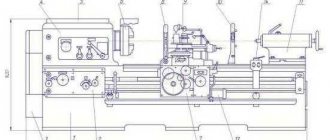
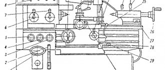
Main parts of the machine
Location and designation of equipment components
1. Drive. 2S132.21.000 (1400 min-1) 2. Gearbox. 2S132.20.000 (1400 min-1) 3. Plunger pump. 2С132К.24.000 4. Feed box. 2С132.30.000 5. Base. 2С132.10.000 6. Speed and feed control mechanism. 2С132.25.000 7. Spindle. 2С132.50.000 8. Electrical equipment. 2С132.95.000* (Russian) Electrical equipment. 2С132.92-1.000* (Remote mechanic) 9. Drilling head. 2С132.40.000 10. Cooling system. 2С132.80.000 11. Fencing of the cutting area. 2С132.45.000* * — Additional option
Technical characteristics of 2S132
| Main settings | Dimensions |
| Maximum height of the workpiece, mm | 600h14 |
| Maximum weight of the installed workpiece, no more than kg | 600 |
| Maximum drilling diameter in steel 45 according to GOST 1050, mm | 3-32 (50**) |
| Limits of threading diameters in medium-hard steel | M3…M33 |
| Maximum weight of the tool installed on the machine, no more than, kg | 6 |
| CHARACTERISTICS OF LIFTING TABLE | |
| Dimensions of the working surface of the table, not less, mm: Width Length Number of T-shaped fastening grooves, pcs. Width of T-slots, mm Distance between T-slots, mm | 500h14 500h14 3 18H12 100±0,4 |
| CHARACTERISTICS OF WORKING SPACE | |
| Maximum spindle movement, mm | 250 |
| Maximum lifting table stroke, mm | 300 |
| Maximum installation movement of the drilling head, mm | 170 |
| Maximum distance from the spindle axis to the guide column, mm | 300 |
| Maximum distance from the end of the spindle to the working surface of the table, mm | 750 |
| SPINDLE CHARACTERISTICS | |
| The size of the inner cone of the spindle end according to GOST 25557 | Morse 4 Morse 5* |
| Cone Accuracy Degree | AT7 |
| CHARACTERISTICS OF THE MAIN DRIVE | |
| Torque on the spindle, no more, Nm | 400 |
| Axial force on the spindle, no more than, H | 15000 |
| Spindle speed limits, min-1: | 31,5…1400±10,1% |
| Number of working feed stages, pcs | 9 |
| Limits of spindle working feeds, mm/rev | 0,10; 0,14; 0,20; 0,28; 0,40; 0,56; 0,80; 1,12; 1,60±10,1% |
The machine complies with safety requirements in accordance with Russian standards, European directives and norms:
- GOST 12.2.009-99. Metalworking machines. General safety requirements.
- GOST R 51333-99 (EN 292-1-91, EN 292-2-91). Machine safety. Basic concepts, general design principles. Terms, technological solutions and technical conditions.
- GOST R 51334-99 (EN 294-92) Machine safety. Safe distances to protect the upper limbs from entering the danger zone.
- GOST R 51335-99 (EN 349-93) Machine safety. Minimum clearances to prevent human body parts from being pinched.
- GOST R 51336-99 (EN 418-92) Machine safety. Installation of emergency shutdown. Functions. Design principles.
- GOST R 51337-99 (EN 563-94) Machine safety. Temperatures of touched surfaces. Ergonomic data for establishing limits for hot surfaces.
- GOST R 51339-99 (EN 811-96) Machine safety. Safe distances to protect the lower limbs from entering the danger zone.
- GOST R 51342-99 (EN 953-97) Machine safety. Removable protective devices. General requirements for the design and manufacture of fixed and movable removable protective devices.
- GOST R 51343-99 (EN 1037-95) Machine safety. Prevent unexpected start-up.
- GOST R 51345-99 (EN 1088-95) Machine safety. Interlocking devices associated with protective devices - Principles of design and selection.
- GOST R 51344-99 (EN 1050-96) Machine safety. Principles of risk assessment.
- GOST R IEC 60204-1-99 Safety of machines. Electrical equipment of machines and mechanisms. Part 1: General requirements.
- Joint EU Machinery Directive (93/68/EG).
- Low Voltage Directive (73/23/EWG).
- EN 954-1 Safety of machinery. Elements of the control system relevant to safety.
- GOST R EN 12717-2006 (EN 12717) Safety of metalworking machines. Drilling machines.
- EN 1005-2 Safety of machines. Human physical capabilities. Part 2. Maximum effort in managing machine-related objects.
- EN 1050 Safety of machines. Principles of risk assessment.
Machine noise level
On the machine, under typical operating conditions at the operator's workplace, the sound level does not exceed 80 dBA.
When the machine is idling at a spindle speed of 1000 rpm, the sound level at the workplace is 76 dBA.
The corrected sound power level is 87 dBA.
The uncertainty of sound power measurement complies with the ISO 3746 standard and at a confidence level of 95% is equal to ± 1.96 σR from the measured value, where σR = 3 dBA.
Noise characteristics were measured in accordance with the methodology of the GOST R 51402-99 standard (ISO 3746-95) taking into account the requirements set out in ISO 230-5 and EN 12840. The actual parameters depend on the dynamic characteristics of the workpiece, spindle speed and other cutting conditions.
Increased machine noise levels are caused by:
— processing of non-rigid and thin-walled workpieces;
— machining with tools with a long reach;
- working with damaged or broken tools;
— work in conditions of intense self-oscillations.
To avoid increased noise when working on the machine, it is recommended to use a working tool with high rigidity.
When processing long parts, use support rests.
When processing thin-walled parts, use vibration-absorbing inserts.
It is recommended to avoid cutting modes in which intense high-frequency self-oscillations occur.
Type of climatic version UHL4 or T3 according to GOST 15150-74. The lower operating value of the ambient air temperature should not be lower than +1ºС, the upper operating value of the ambient air temperature should not be higher than +35ºС, the relative humidity should be no more than 80% at 25ºС. The dust content of the room is within the sanitary norm.
The machine should not be exposed to local heating and strong temperature changes.
Operating mode of the machine and brand of oils and coolants:
Operating mode - Manual
The recommended brand of coolant that does not affect the performance of oil-resistant rubber products is Emulsol “ROSOIL-500” TU 0258-009-06377289-2000
Amount of coolant poured - 18.7 l
Acceptable brands of oils in the lubrication system are INSp 65I-20A GOST 20799-88 LKS-2
| OVERALL DIMENSIONS AND WEIGHT | |
| Overall dimensions of the machine, no more than, mm: Length x width x height | 870x1110x2700 |
| Area occupied by the machine, m2 | 0,97 |
| Machine weight, no more, kg | 1200 |
| CHARACTERISTICS OF ELECTRICAL EQUIPMENT | |
| Type of supply current GOST R IEC 60204-1 - current frequency, Hz -voltage, V | Variable three-phase 50±1 380+10%, -15% |
| Main drive motor: Rated power, kW Rated rotation speed, min-1 | 4 1430 |
| Indicators of accuracy and roughness of processing (per batch) of sample products: accuracy: When drilling: When deployed | H12 H8 |
| Roughness of the internal surface of the product sample, Ra: after drilling after deployment | 6,3 1,6 |
| ** Drilling holes with a diameter of more than 35 mm is allowed at minimum feeds (S=0.1; 0.14 mm/rev) and revolutions (n=63; n=90 mm/rev), and with preliminary drilling of a hole of a smaller diameter. *Option | |
Main types of work on vertical drilling machines 2S132 and 2S132K:
— various drilling operations on metal, in manual and semi-automatic mode. The mechanical feed of the tool is adjusted through its own feed box.
— thread cutting, internal, metric. The amount of feed stroke, the feed speed of the tap and the inclusion of reverse are adjusted.
— drilling holes of larger diameter, drilling in cast iron, non-ferrous alloys, countersinking, reaming
— on the 2S132K machine there is the possibility of longitudinal and transverse feed of the workpiece, like a milling machine. Milling of small workpieces is possible.
Equipment and accessories of the machine 2С132
The machine is supplied by the manufacturer in the following form:
- the movable table is in the lower position with a beam clamped in a vice, against which the drilling head rests; the table and drilling head are clamped to the column with clamping bolts;
- the drilling head is lowered onto the table stop and onto a wooden block clamped in a vice fixed to the table;
The assembled machine, including electrical equipment, is packed in box No. 1.
The accessories that are included in the kit and the cost of the machine are packed in box No. 2: Handle for lifting the table and drilling head, keys to the electrical cabinet D73-72, 2 pcs., elastic coupling.
Accessories available at extra cost (packed in separate boxes)
Adapter bushings
- 6100-0142 (0202), 3/1
- 6100-0144 (0204), 4/2
- 6100-0145 (0205), 4/3
- 6100-0146 (0206), 5/3 *
- 6100-0147 (0207), 5/4 *
Wedges for the tool
- 7851-0012, *
- 7851-0013, *
- 7851-0014, **
Keys 7812-0375, 7812-0378; Screwdriver 7810-0327; Wrench 7811-0023(17-19); Drill chuck PSS-10; Mandrel 6039-0022; Vice ST160.000; Floating table SP 132.000; Cross table SK02.000; Cooling pump; Packaging of the machine is as agreed with the customer.
Technical documentation
- Manual. Part 1. 2S132.00.000RE1
- Manual. Part 2. Electrical equipment. 2S132.95.000RE2*
- Operating manual Part 2. Electrical equipment. 2S132.92-1.000RE2*
- Manual. Part 3. Acceptance information. 2S132.00.000RE3
- Operational documents for components for: machine vice, main motion motor, cooling pump
*Option; ** For machines with KM5 taper
Machine workspace - diagrams, symbols and explanation
At the installation site of the machine, it is necessary to ensure the following: - sufficiently free space around the machine; — sufficient space for the operator to move; — sufficient space for maintenance and repair work; — the door of the machine electrical cabinet must open completely at least 120º; - area for placing racks for workpieces and products, a hopper for workpieces (products), a cart for chips, a cart for tools, etc.
It is undesirable to place grinding machines operating without cooling, large grinding and forging equipment near the machine.
Installation and connecting dimensions of the machine, sketches of the end of the spindle and lifting table
Mechanics of the main movement (spindle) and mechanics of feeds
Control panel with symbols and controls
Graphic symbols on the machine
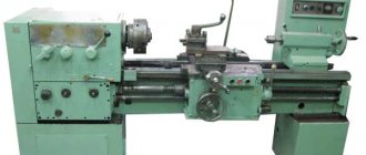
Application and description of the drilling machine 2S132L:
for drilling work on metal, these are usually large and tall workpieces; a vice with a workpiece can be installed on the base of the machine or on a rotary tilting table. The rotation of the desktop is carried out by a round column. The 2S132L drilling machine can be used in workshops for small jobs and in industrial production for serial work. The drill feed is manual or mechanical, gear shifting is geared. Productivity can be single, when constant readjustment is required when changing workpieces, or serial, for this purpose the machine has automatic tool feeds into the processing zone.
Characteristics of electrical equipment
| Main settings | Dimensions |
| Power supply: Type of current Current frequency, Hz Voltage, V | alternating, three-phase 50 (60*) + 2% 380 (220*) +10% |
| Main drive electric motor: Rated power, kW Rated rotation speed, min—1 | 4 1430 |
| Cooling system electric pump: power, kWt Feed, l/min | 0,12 22 |
| Number of electric motors on the machine | 2 |
| Total power of electric motors installed on the machine, kW | 4,12 |
Electrical equipment protection degree
The electrical panel is mounted in the niche of the column.
The niche door is equipped with a special lock and key, and there is also a warning sign “Dangerous Voltage”.
The control panel housing has a degree of protection IP44, the niche of the column has a degree of protection IP43 according to EN 60529.
Connecting the machine to the electrical network must be carried out by specially trained personnel who have permission to work with electrical equipment up to 1000 V, who have familiarized themselves with section 2S132.95.000RE2 or 2S132.92-1.000 RE2.
After connecting to the mains, all electrical equipment must be checked for perfect operation. The machine must be properly grounded and all outputs are properly insulated. Set all switches to their home or zero positions, and check that all machine switches, manual limit switches and other switches are set correctly for reliable setup.
After installing the machine, before connecting it to the workshop network, it is necessary to measure the electrical resistance between the grounding bus and any metal part of the machine with elements of electrical equipment located on it, which may be under voltage above 24V as a result of breakdown of wire insulation. The measured resistance should not exceed 0.1 Ohm.
Safety measures
Occupational safety on the machine is ensured by its manufacture in accordance with the requirements of GOST 12.2.009-99, EN 292-1.2 and EN 60204-1.
Labor safety on the machine is ensured by the presence in the design of the machine of the following devices, made in accordance with the requirements set out in Russian standards, European directives and norms:
— protective fence of the cutting zone;
— blocking;
— external device for locking the input switch;
— handle latches;
— safety devices.
Protective and safety devices
The machine is equipped with a movable guard that covers the end of the spindle, chuck and cutting tool while the main drive rotates. When the guard is removed from the spindle, the power supply to the machine control circuits is blocked in the off state.
The removal of drain chips should be done using a special metal hook while the spindle rotation is stopped. Small chips can be removed with a brush when the tool is rotated in the retracted state.
The mechanism is equipped with a blocking end of the protective fence of the cutting zone and prohibits rotation of the spindle while the guard is removed from the cutting zone. Restarting the spindle is possible only by pressing the start buttons with the guard in the closed position.
The machine has automatic spindle braking. The spindle braking time after turning it off at all rotation speeds does not exceed 5 s. At a spindle speed above 3000 min-1, the braking time after turning it off is not regulated.
The handles and other controls of the machine are equipped with reliable locks that prevent spontaneous movements of individual assembly units of the machine.
Locking the input switch. For Russian-made electrical equipment: the automatic input switch-disconnector is located on the right side of the column. After turning off the machine, the switch must be locked with a special lock. For electrical equipment: The input switch-disconnector is located on the right side of the column and has a locking device. Turning on the input switch-disconnector must be impossible without a lock not included in the delivery set. For installation/removal of a padlock during its operation, there are holes on the handle of the input switch drive.
The machine is equipped with a safety clutch in the feed chain against overload, adjusted according to the axial force by 15% more than the permissible one. If the safety clutch snaps, the operator must stop the machine and change the cutting mode.
A spring counterweight prevents spontaneous lowering of the spindle and ensures smooth movement throughout the entire stroke.
The machine control panel has an “Emergency Stop” button with an oversized mushroom-shaped pusher, edged with a yellow circle.
Safety precautions when preparing for work and when operating the machine
Before connecting the machine to the power supply, you must check:
— reliability of contact of grounding wires;
— correspondence of voltage in the network and electrical equipment of the machine.
Familiarize yourself with the purposes of all governing bodies.
Check when the machine is idling:
— operation of mechanisms built into the drilling head;
— serviceability of signal, brake and push-button devices;
— correct operation of locking devices;
— serviceability of the lubrication system and cooling system;
— the presence on the machine of rigid stops that limit the movement of the drilling head and table.
Installation movements of the drilling head are made only with the wedges pressed out.
It is not recommended to switch spindle speeds and feeds on the fly.
When drilling is complete, turn off the coolant supply.
If there is no coolant in the cooling system, be sure to turn off the coolant switch.
Attention! It is unacceptable for the pump to operate in the absence of coolant in the cooling system.
Safety precautions when transporting and installing the machine
During installation, dismantling and repair, for reliable mooring and safe movement of the machine, you should use special holes in the column, removing the plugs installed in them during packaging.
Lifting devices should be selected taking into account the weight of the machine and the instructions in the corresponding section of the passport (installation and initial start-up of the machine).
When transporting the machine, the drilling head remains in the lowest position, rigidly fixed to the column.
When transporting to the installation site and when lowering onto the foundation (floor), the machine should not be subjected to strong shocks.
Loading and unloading of the machine must be carried out by qualified personnel.
The slinging diagram for the machine in the package is indicated on the packaging.
The machine should be connected to the low-resistance workshop grounding circuit in strict accordance with the instructions in the “Operation Manual for Electrical Equipment” 2S132.95.000RE2 or 2S132.92-1.000 RE2 (depending on the configuration).
When assembling and setting the machine into working position, special attention should be paid to removing the table stops and wooden beams. The drilling head may fall onto the table if the work order is not followed.
Areas of application of the machine model 2С132
The vertical drilling machine model 2C132, the operation of which is allowed in the temperature range from +1 to +35 degrees Celsius, can be effectively used not only for drilling holes, but also for performing a whole list of other technological operations:
- drilling and boring holes;
- deployment;
- countersinking;
- internal thread cutting;
- end trimming.
The main machine controls are located on the front panel
By special order, the machine manufacturer produced models 2C132, which can operate in a wider temperature range - from -10 to +45 degrees Celsius. The operating manual for the vertical drilling machine in question prohibits exposing the equipment to local sources of high temperature, since this can seriously damage its electrical circuit and individual elements.
The design of the 2S132 machine is quite complex, so only specialists who have undergone special training, which was previously (at the time of the model’s release) carried out within the manufacturing enterprise, are allowed to work on such equipment.
Packaging, storage, unpacking and transportation 2С132
To protect the machine, accessories, tools, replacement and spare parts from corrosion during transportation, a corrosion-protective lubricant is applied to all unpainted surfaces, i.e. conservation is carried out. Preservation and re-preservation are carried out in accordance with GOST 9.014-78 and OST 2-N89-30-79.
Preservation of the machine must comply with group P-1; tools, replacement and spare parts - group 1-2. Temporary protection option: B3-1. Internal packaging option: for internal deliveries – VU-1; for export supplies - VU-5. The warranty period of protection without re-preservation is 1 year. Depreservation is carried out with low-viscosity oils or solvents, followed by wiping dry.
Reactivation of the machine. After installation, the machine must be thoroughly cleaned of the anti-corrosion coatings applied to the open, as well as treated and untreated surfaces of the machine covered with casings and shields.
Cleaning is done with a rag soaked in white spirit. Then, to avoid corrosion, coat the cleaned surfaces with a thin layer of industrial oil I-20A GOST 20799-88. The use of metal objects or sandpaper to clean the machine is not allowed.
The machine is packed with corrosion-protective paper and a polymer cover.
All accessories, tools, replacement and spare parts, documentation included with the machine are packed in boxes, placed in the machine packaging box and securely fastened in the box of the transported machine. Bulk (under a cover) shipment of products is allowed, which is negotiated with the user and fixed in the contract. The documentation supplied with the machine is packaged in a plastic film bag and placed in a document box, which is placed in place No. 1.
For microclimatic regions with moderate and cold climates in any type of atmosphere, the machine should be stored under a canopy and/or indoors, where fluctuations in temperature and humidity do not differ significantly from fluctuations in the open air. Climatic factors: air temperature ± 50ºС. The average monthly relative humidity during the warmest and most humid period is 80% at 20ºC, lasting 6 months. The upper value of relative humidity is 100% at 25ºС. For any microclimatic areas, including areas with a tropical climate, the machine should be stored indoors with natural ventilation (without artificially controlled climatic conditions), where fluctuations in temperature and air humidity are significantly less than in the open air. Climatic factors: air temperature ± 50ºС. The average monthly value of relative air humidity in the warmest and most humid period is 70% at 27ºС, the upper value of relative humidity is 98% at 35ºС. It is not allowed to store the machine in packaged form beyond the warranty period of protection without re-preservation.
When unpacking, you must first remove the top panel of the packing box, and then the side panels. Care must be taken not to damage the machine with the unpacking tool.
When unpacking the machine, it is especially important to ensure that the corrosion protective film or paper is removed after the machine and room temperatures have equalized (usually after 48 hours). Otherwise there is a risk of corrosion due to condensation.
When unpacking, you must check the completeness of the delivery and/or any possible damage during transportation. After unpacking, you should check the external condition of the components and parts of the machine, as well as the presence of its components, tools and accessories, spare parts and technical documentation removed from the machine and packaged separately in accordance with this manual.
The machine can be transported by all types of transport. Before delivering the machine, carefully plan its unloading and transportation to the installation site. When your machine is delivered, the transport and lifting equipment must be in full readiness. Before delivering the machine, any obstacles in the way of transportation from the unloading point to the installation site must be removed. During transportation, keeping people in the danger zone is unacceptable!
Machine transportation diagram
Special instructions for transportation:
Only use vehicles with sufficient carrying capacity, i.e. more than the specified transport weight! When choosing lifting devices (belts, chains, ropes, etc.), be sure to ensure that their maximum permissible lifting capacity is sufficient for the transported weight! The weight of the packaged machine is indicated on the box. When unloading the packaged machine, be sure to follow the instructions on the outside of the packaging! When transporting to the installation site and when lowering it onto the foundation (floor), it is necessary to ensure that the machine is not subjected to strong shocks and shocks. Before transporting the unpacked machine, you must make sure that the moving components are securely fastened: - the movable table is in the lower position; — the drilling head is lowered onto the table stop and onto a wooden beam clamped in a vice mounted on the movable table; — the head stop is turned out and secured to the table stop. The machine can be shipped without a vice. In this case, the drilling head is lowered onto a wooden beam fixed in the rear groove of the table, pressed and secured to the column with clamping screws. The table is also fixed. The drill head stop is turned out and secured to the table stop.
Transportation of the machine is carried out according to the transportation scheme. To transport the unpacked machine, use a Ø35 mm rod, which is inserted into the holes of the column. In this case, it is necessary to protect the protruding parts and the lining of the machine, for which purpose wooden spacers are placed under the rope. After transporting the machine using lifting equipment and transport openings, the transport openings must be immediately closed with the plugs located in the spare parts box.
How to install a drilling machine 2С132
The accuracy of the machine depends on the correct installation. Alignment of the installation of the machine in the horizontal plane is carried out using a level installed on the movable table in the longitudinal and transverse directions (the foundation bolts must not be tightened). In each table position, the level deviation should not exceed 0.02 mm/m (in the longitudinal and transverse directions).
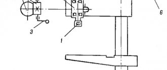
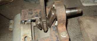
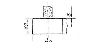
Installing the drill head into working position
To install the drilling head in the working position, you must: – check the reliability of the fastening of the wooden beam, pos. 3 in a vice pos. 4; – press out the table and head by unscrewing the corresponding original clamping screws on the head wedges, pos. 1 and table pos. 6 for 1-2 turns; – lift the table together with the head up using the table lift handle pos. 5 until the head lift gear is completely engaged with the rack mounted on the column, while simultaneously rotating the head lift shaft with a handle through square 7 located on the left side of the head to avoid gear breakage. – screw in the removed stop 9, which limits the lower position of the head; – tighten the clamping screw on the head wedge; – lower the table to the working position; - tighten the clamping screw on the table wedge; – release the vice; – remove the beam; – screw in the second stop pos. 2 limiting table travel. At the bottom of the drilling head there is a stop pos. 8, limiting the upward movement of the drilling head. If necessary, adjust the table wedges and drilling head in accordance with section 10 of this manual.
Working without a stop limiting the lower position of the head is unacceptable!
All transport fastenings must be removed before commissioning. Save any removed shipping guards for future use.
Before starting the machine, it is necessary to pour 8 liters of industrial I-20A oil into the drill head reservoir, and 18.7 liters of coolant per machine into the base plate reservoir. Then ground the machine and connect it to the electrical network, first checking that the network voltage matches the voltage of the machine equipment. Follow the instructions from the passport related to the start-up and set out in the section, as well as in the appendix to the operating manual “Electrical equipment of the machine”.
ATTENTION! When connecting the electrical equipment of the machine, it is necessary to strictly observe the correct phase sequence. Otherwise, spindle reverse operation is impossible.
After familiarizing yourself with the control handles, you should manually check the operation of all machine mechanisms. After connecting the machine to the network, you need to test the machine at idle speed at the lowest spindle speeds with the feed turned on, and try turning on all spindle speeds and feeds, starting with the lowest ones. If, when switching speeds and spindle feeds, the movement of the handle is obstructed, you should not increase the force on the handle; you need to press and hold the “SPINDLE ROTATION” button TO TURN THE GEAR WHEELS.
It is forbidden to switch speeds and feeds on the fly, as this can lead to breakage of the gear teeth. After making sure that all the mechanisms of the machine are working properly, you can begin setting it up for operation.
Foundation
The foundation must provide a reliable foundation for the machine, ensuring maximum use of its capabilities in terms of productivity and accuracy over a given service life and eliminating the influence of the machine on the operation of adjacent equipment.
The depth of the foundation is taken depending on the soil, but must be at least 300 mm. The machine is secured to the foundation with four M16 foundation bolts.
If there is a reinforced concrete floor, the machine can be installed on vibration-isolating supports.
Machine installation diagram, plan dimensions and foundation plan
Starting the machine
Setting up the machine for operation consists of installing the table and drilling head in the positions required for operation, clamping them on the column, setting the required rotation speeds and spindle feeds.
The machine provides the following modes: - manual spindle feed, - mechanical spindle feed.
Attention! The machine is delivered in the manual spindle feed position.
Drilling head
To turn on the mechanical feed of the spindle, you must press button 8 and move cap 10 along the shaft axis to the right (away from the machine). With a sharp movement, turn the steering wheel towards yourself (approximately 200). Mechanical feed is enabled.
To switch to the manual spindle feed mode, you need to turn the steering wheel away from you and move cap 10 to its original position. Button 8 should lock the position.
When setting up work with the spindle feed turned off at a given depth, the following sequence of operations must be observed: 1. Install the tool in the spindle. 2. Secure the workpiece on the table. 3. Lower the spindle until the tool stops in the part, press out the screw and install the dial of the drilling head so that opposite the pointer there is a number corresponding to the depth of processing, taking into account the sharpening angle of the tool, then secure the dial. The cam with the letter “P” must be secured so that its mark coincides with the corresponding mark on the dial. After turning on the rotation and feed of the spindle, processing of the part begins. When the desired machining depth is reached, the spindle feed will stop and the spindle will continue to rotate. To stop it, you need to press the “STOP” button to stop the spindle.
When cutting threads on a machine with a spindle reverse at a certain depth, set the dial on the drilling head so that the number corresponding to the processing depth is opposite the pointer. Align the cam mark “P” with the corresponding mark on the dial and secure the cam. Turn off mechanical feed. After turning on the spindle, manually insert the tap into the hole. After 2-3 spindle revolutions, there is no need for manual feed. When the specified cutting depth is reached, the spindle is automatically reversed and the tap exits the hole. To rotate the spindle to the right, you must press the corresponding button.
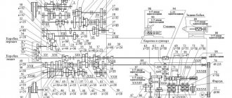
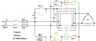
Kinematic diagram
Due to the simplicity of the kinematic chains of the main movement (spindle rotation), feed movement, the sequence of rotation transmission from the electric motor to the actuators is not explained. The operation of the relevant components is described in detail in the Operation Manual.
Kinematic diagram
List of kinematic diagram elements
Any spare parts for the drilling machine can be ordered from us. Look in the “Technical equipment and spare parts” section, or use the site search - “2С132”.
Floating table design
The characteristics of the floating table with which the equipment is equipped make it possible not only to securely fix the workpieces, but also to conveniently position them in relation to the cutting tool. This mechanism of the 2S132 vertical drilling machine consists of the following elements:
- bearing surface;
- guide slides;
- grounds.
This is what the overhead floating table looks like for the 2S132 machine and its modifications
Smooth and precise movement of the work table in the longitudinal and transverse directions is ensured by needle bearings installed in the slide assemblies. In order for the processing of a part to be accurate, it is necessary to ensure reliable fixation of the work table in a given position, for which the following elements in its design are responsible:
- eccentric shaft;
- upper and lower thrust;
- two wedge mechanisms.
In order to control the clamping mechanism of the work table and regulate its operation, its design uses a screw mechanism. The characteristics of this unit and the elements of which it consists ensure reliable operation of the clamping device.
Lubrication system
Machine lubrication is provided by the following systems:
1) circulation; 2) padding.
Lubrication diagram for machine 2S132
Lubrication map
2 - Bearings, gears of the gearbox, feeds and the gear and feed switching mechanism.
Lubricant material: Oil I-20A GOST 20799-88. Lubrication method: Circulation from a pump. Frequency: once every 6 months. Lubricant consumption for a specified period: 8 dm³.
3 - Spindle supports. Lubricant material: Lubricant LKS-2 or CIATIM 201 GOST6267-74. Lubrication method: Packing. Frequency: 1 time in 2 years. Lubricant consumption for a specified period: 0.04 kg.
4 - Guide columns. Lubricant material: Oil I-20A GOST 20799-88. Lubrication method: From above. Frequency: 1 time per shift. Lubricant consumption for a specified period: 0.02 kg.
5 - Table lift roller. Lubricant material: CIATIM-201 lubricant GOST 6267-74. Lubrication method: Grease nipple. Frequency: once every 6 months. Lubricant consumption for a specified period: 0.02 kg.
11 - Drive bearings. Lubricant material: CIATIM-201 lubricant GOST 6267-74. Lubrication method: Packing. Frequency: once every 12 months. Lubricant consumption for a specified period: 0.02 kg.
The circulation system lubricates the gearbox, feeds, feed mechanism, drilling head, the body of which is an oil reservoir, from the plunger pump 10 through check valves 8 and 9 on the suction line. Oil indicators 1 and 7 indicate the presence of oil in the tank. The plunger pump is attached to the bottom plate of the gearbox housing and is driven by an eccentric mounted on the gearbox shaft. The oil supplied by the pump flows through the slots in the tubes onto the gears, shafts, bearings of gearboxes and feeds, and the drilling head, then flows back into the oil reservoir 6.
The lower bearings of spindle 3 are lubricated by pumping grease through a grease nipple.
Modifications of the vertical drilling machine 2S132:
— universal vertical drilling machine 2S132. It has a rigid cast-iron frame, guiding movements of the vertical unit, and a mechanical spindle feed.
— vertical drilling machine 2S132K with an overhead cross table. At the Customer's request, the rectangular table can be replaced with a round, rotary one, sizes vary.
— drilling machine 2S132P. Additionally, it has an increased accuracy class P, according to GOST. Designed for high-precision drilling work, possibly for deep drilling.
Vertical drilling machine 2S132 price – 450,000 rubles.
Made in Russia, 1 year warranty.
High precision vertical drilling machine 2S132P price – 520,000 rubles.
Manufactured in Belarus, accuracy class P according to GOST, warranty 2 years.