Today we will talk about how to independently connect a 380V welding machine for its further use. It’s worth warning right away that if the welding machine will be used at home, it is very important to know what load the machines in the electrical network of your house or apartment can withstand. And only after that choose an inverter of the desired type and power. When choosing a welding machine, of course, you need to take into account many important characteristics. We will describe the main points that you must pay attention to when choosing this rather expensive equipment. It is important to choose a unit that can be used to perform a maximum of tasks, but also that the cost corresponds to the stated parameters. So, what is it worth focusing on?
Operating principles of a 380V welding machine.
- Current consumption power. For example, in order to carry out welding work at home, a welding unit with a power of up to 5 kW is sufficient. Buying a device with a higher energy consumption threshold will be a waste of money.
- Resistant to power surges. Since in the power supply network there often occurs both a sharp drop and a sharp rise in current voltage.
- What network voltage range is the connected welding machine designed for?
After assessing all of the listed parameters, as well as some other important conditions, you will already know how to properly connect the welding machine to the power supply. We will try to help a little with this and describe the technical key points.
Industrial products
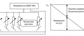
Industrial designs of generators used to supply power to mobile welded equipment can have a wide variety of designs. From the point of view of economy and efficiency, the option of a gasoline unit of the same inverter type is considered optimal. In this case, preference is usually given to devices from the same manufacturers, designed specifically for working with inverter welding equipment (figure below in the text).
It is believed that it is this combination of these two components of the working complex that makes it possible to obtain a sufficiently stable arc and provide the required parameters of high-frequency voltage and pulse current. According to their class and intended purpose, all existing welding devices are divided into the following types:
- Purely industrial designs;
- Professional models;
- Inexpensive household products.
Industrial and professional models are mainly used for the manufacture of volumetric metal structures and are designed for round-the-clock operation for long periods of time. For their normal functioning, significant operating currents will be required, capable of ensuring high-quality assembly of industrial structures. This type of welding device will require gasoline generators capable of delivering currents of up to 250-500 Amperes (see photo below).
Summarizing the consideration of possible options for choosing a generating device for an inverter, it is necessary to note the following. When thinking about the question of which generator is best to choose for welding, most users give preference to small-sized gasoline units in inverter design.
Welding rectifier - features of operation and assembly
To perform certain types of welding work, for example, with stainless steel, the use of alternating current supplied by a transformer is not used. To work with such metals, a constant voltage supply is required. In addition, direct current cutting reduces the consumption of electrodes, and metal spattering is prevented during welding.
To perform work in such conditions, welding rectifiers are used, which allow welding with direct and reverse polarity current. If you have experience in installing electronic circuits, then you can also assemble such a device yourself.
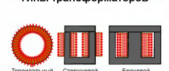
The basis of the welding rectifier will be the same step-down transformer. The difference lies in the presence of a rectifying electronic circuit. If desired, you can remake the already described welding transformer or assemble a universal device that will allow you to weld with both alternating and direct current.
The simplest diagram of the electronic part of a welding rectifier looks like this:
When assembling such devices, the following design features should be taken into account:
The main part of the device is a rectifier bridge made of powerful power diodes. They are connected according to the diagram, taking into account polarity. Smoothing of current ripple is carried out due to a filter made on the capacitor and choke coil
Please note that the components must have a margin of 2.5 - 3 permissible voltage. When working with high currents, the elements heat up. Semiconductor diodes are sensitive to overheating
Therefore, they are installed on radiators, which will increase the intensity of heat removal. When enclosing the device in a housing, it becomes mandatory to use a fan to increase cooling efficiency.
We pay attention to the connection of individual elements of the circuit. Considering that they will be exposed to high current, it is necessary to ensure reliable contact
If this is not done, then the wires in these areas will heat up and burn out. The preferred option is with fastening using platforms with a bolt and nut.
The choke in such designs is made in the form of a separate remote inductor, which is connected as needed. Note that installing a rectifier does not prevent the welding current from changing using the secondary winding coil position regulator.
As you can see, there are no difficulties in assembling a welding machine yourself. But it’s worth working on such devices only if you have experience in designing simple devices that operate with lower currents. Otherwise, entrust the assembly to a specialist or buy a factory welding machine.
Microwave welding machine:
How does a welding inverter work?
The formation of a high current, with the help of which an electric arc is created to melt the edges of the parts being joined and the filler material, is what any welding machine is designed for. For the same purposes, an inverter apparatus is also needed, which allows the generation of welding current with a wide range of characteristics.
In its simplest form, the principle of operation of the inverter looks like this.
- Alternating current with a frequency of 50 Hz from a regular electrical network is supplied to the rectifier, where it is converted into direct current.
- After the rectifier, the direct current is smoothed using a special filter.
- From the filter, direct current flows directly to the inverter, whose task is to convert it again into alternating current, but at a higher frequency.
- After this, using a transformer, the voltage of the alternating high-frequency current is reduced, which makes it possible to increase its strength.
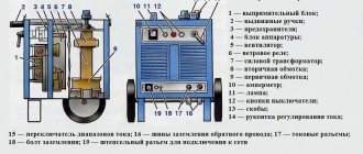
Block diagram of an inverter type welding machine
In order to understand the importance of each element of the electrical circuit diagram of an inverter device, it is worth considering its operation in more detail.
Application of a current generator
So, you checked your wiring and it turned out that connecting a 220V welding machine is simply impossible. What to do in this situation? You can use a third-party current generator.
And at this moment, many immediately begin to remember that they keep an old gasoline generator in their dacha, which more than once saved them from sudden power outages. On the surface, the use of such generators seems like a pretty good idea, but in practice everything is different. Often, all gasoline generators are low-power and are not capable of providing a voltage of more than 5 kW for a long time.
As you understand, connecting a welding inverter to a low-power gas generator is simply pointless. To find out how much power you need, simply multiply the amperage you'll be cooking with by the voltage.
Let's take the most popular situation: you are welding with a 3 mm electrode with a current of 120 Amps and a voltage of about 40V. We multiply 120 by 40, we get 4.8 kW. This is the minimum power that a gas generator must provide. But in the calculations we did not take into account the efficiency of the welding machine, which is less than 100%. To ensure uninterrupted operation of the inverter you need at least 6 kW.
In general, a gas generator is a choice for those who no longer have any opportunity to obtain an additional power source. Ideally, before purchasing an inverter, you should check all the wiring and, if it is unsuitable, buy a welder with a built-in generator. Yes, these models are expensive and very bulky. But this is the most convenient solution to the problem.
If this solution is inconvenient for you, then you can buy a special current stabilizer for the welding machine. It connects directly to the welding inverter. This solution is suitable for a more or less stable power grid.
Best Cheap Generators
To make it easier for you to choose a generator for your welding machine, we will additionally tell you about four high-quality models for your home and garage. This is not a rating, but rather a list of excellent generators that have performed well in a variety of conditions.
Huter DY6500L
The Huter DY6500L generator is an excellent helper in the household. Its power is 5 kW, which is enough to power a low-power inverter delivering up to 150 Amps. This is a synchronous generator running on gasoline fuel. For full operation, it is recommended to use gasoline of a grade not lower than AI-92. This model can also run on propane. Tank with a capacity of 22 liters.
Huter DY6500L is started using a recoil starter. There is a built-in forced cooling system, it is of the air type. The weight of the generator is about 80 kg, which is quite a lot. But two or three people can move it to the right place without any problems.
BRIMA LT 8000 B
We also recommend the LT 8000 B model from the famous German brand BRIMA for inverter welding. Its power is slightly more than that of the previous generator - 6 kW. But this is its rated power. And the maximum is 6.5 kW. However, remember that we do not recommend constantly using the generator beyond its capabilities. The LT 8000 B model is useful for those whose machine produces up to 180 Amps of welding current.
This is also a gasoline generator. Tank capacity - 25 liters. Powered by a reliable 190F engine. It is four-stroke, equipped with forced air cooling. Starting is carried out using built-in electronics. The generator can work without a break for up to 8 hours, then it needs a break to avoid overheating.
Safety regulations
The connection diagram for an inverter welding machine is quite simple and allows the device to operate in a cyclic (intermittent) mode, which allows for maximum welding efficiency. Before plugging into a socket, you still need to read the connection instructions, check the network parameters, completeness of the equipment and the external integrity of all its parts.
Options for connecting the inverter to the network
The instructions should clearly describe how to properly connect the welding machine, and also stipulate the procedure for its safe connection to the current electrical network. The need to check plugs and circuit breakers installed in the power supply circuit is specifically stated.
The fact that in old houses aluminum wiring does not allow working with currents above 10 Amperes should also be taken into account. Therefore, before connecting converters to the network, it is necessary to find out their rated power and current consumption.
When assessing the power taken from the network, one should not forget that when the device is turned on, there is a sharp surge in the starting current, the value of which can exceed the rated value several times.
Before connecting the device and welding work, the operator must fulfill the following requirements of the operating instructions:
- remove foreign electrical devices (computers, transmitters, measuring instruments) from the device body;
- when working with inverter equipment, the workplace must be cleared of all other interfering objects;
- The rooms in which the welding unit is located must be equipped with a forced ventilation system.
To avoid emergency situations, before connecting the welding machine for the first time, it is recommended to test it in various welding modes.
Installation and connection of the unit
To use an inverter efficiently and safely, you first need to properly prepare it for operation. This process is carried out in several stages. The first task is to install and connect the unit. Installation of the inverter must be carried out according to certain rules:
- the unit must be placed so that it is at a distance of at least 2 m from walls or any objects;
- the device must be grounded;
- the welding location must be chosen so that it is away from flammable objects;
- It is recommended to cook either on a free area or on a metal table.
The inverter can be connected both to a household network (220 V) and to a network with a voltage of 380 V, which is usually used in production. If you plan to use the unit away from electrical networks, then it can be connected to a generator, diesel or gasoline.
Electrical connection
Connecting a welding machine to a household electrical outlet often causes problems. The reason for their occurrence may be old wiring or insufficient diameter of its wires. Typically, wiring is designed for current up to 16 A. And since all switched on devices in the house can exceed this value, circuit breakers (automatic circuit breakers) are installed for safety reasons. Therefore, when connecting, you need to know the power of the welding machine so that it does not trigger the machine.
Connecting the inverter to a household network
You should also pay attention to network sag. If, when you turn on the inverter, you notice a decrease in voltage in the electrical network, this indicates an insufficient cross-section of wires
In this case, it is necessary to measure to what values the voltage drops. If it drops to values below the minimum values with which the inverter can operate (indicated in the instructions), then the device cannot be connected to such a network.
Using an extension cord
The network cable connected to the inverter meets all power requirements and does not cause connection problems. But if its length is not enough, then you should select an extension cord with a wire cross-section of at least 2.5 mm2 and a length of no more than 20 meters. Such parameters of the extension cord will be enough for the inverter to operate with a current of up to 150 A.
Connection to generator
In cases where it is not possible to connect the device to the mains, you can connect it to a generator that runs on either gasoline or diesel fuel. Gasoline power plants are the most widespread. But not all of them are suitable for connecting welding machines. In order for the inverter to operate effectively, the generator must have a power of at least 5 kilowatts and produce a stable output voltage. Voltage fluctuations can damage the welder.
You should also consider what diameter electrode you will be working with. For example, if the electrode has a diameter of 3 mm, then an operating current of about 120 A with an arc voltage of 40 V will be required. If we calculate the power of the welding inverter (120 x 40 = 4800), we get a value of 4.8 kW. Since this will be the power consumed, a power plant capable of producing only 5 kW will operate at the limit of its capabilities, which will significantly reduce its service life. Therefore, the generator must be selected with some power reserve, approximately 20-30% higher than that consumed by the inverter.
Wiring and socket requirements
Table of required technical characteristics for a welding machine
According to the principle of operation, a welding machine is a current converter into a welding arc. The operating current range (equipment power) is the main characteristic of the device, which determines its technical parameters. It must be consistent with the building's electrical capabilities. To determine this, the network voltage is multiplied by the maximum permissible current value (indicated on the input panel). Compare the obtained value with the data in the equipment data sheet.
From a 220 V household outlet, you can only power an inverter device, which is a more advanced device with many settings and safety parameters. In this case, it must have a built-in refractory fuse or circuit breaker. In old houses, the wiring is designed for a maximum current of 10 A, and when the device is started, there is a jump to 40 A - in such buildings you need to connect to the panel.
A transformer device, which is designed to operate from 380 V, is connected only through the electrical panel. If the wiring is weak, it is recommended to use a gas generator.
Connecting welding cables
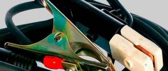
There are 2 terminals on the front panel of the inverter, next to which there are markings in the form of “+” and “-” signs. Welding cables are connected to these terminals, one of which has a metal clip (clothespin) at the end, and the second has a holder for the electrode. Both cables can be connected to both terminals, depending on the welding method, which will be discussed later. After connecting the cables to the machine, one of them, which has a clothespin, is connected to the welding table or to the workpiece.
In some cases, standard cable lengths may not be sufficient, for example when working at heights. In such situations, the question arises: is it possible to extend the welding cable? Professionals do not advise doing this, especially if it concerns an inverter device. This fact can be explained by the fact that each cable has certain resistance characteristics. Therefore, “leaks” of voltage and current along its entire length are inevitable. Therefore, the longer the cable, the more the voltage sags.
If you try to compensate for the loss of voltage and current by adding values on the unit panel, then this measure will most likely damage the inverter electronics. It turns out that it is easier to bring the device closer to the welder’s workplace than to spend a considerable amount on repairing the unit after lengthening the cables.
Advantages and disadvantages of inverter-type welding machines
Inverter welding machines, which replaced the usual transformers, have a number of significant advantages.
- Thanks to a completely different approach to the formation and regulation of welding current, the weight of such devices is only 5–12 kg, while welding transformers weigh 18–35 kg.
- Inverters have very high efficiency (about 90%). This is explained by the fact that they spend significantly less excess energy on heating the components. Welding transformers, unlike inverter devices, get very hot.
- Due to such high efficiency, inverters consume 2 times less electrical energy than conventional transformers for welding.
- The high versatility of inverter machines is explained by the ability to regulate the welding current over a wide range with their help. Thanks to this, the same device can be used for welding parts made of different metals, as well as for welding using different technologies.
- Most modern inverter models are equipped with options that minimize the impact of welder errors on the technological process. Such options, in particular, include “Anti-stick” and “Arc Force” (fast ignition).
- Exceptional stability of the voltage supplied to the welding arc is ensured by the automatic elements of the inverter electrical circuit. In this case, automation not only takes into account and smoothes out differences in input voltage, but also corrects even such interference as the attenuation of the welding arc due to strong wind.
- Welding using inverter equipment can be performed with any type of electrode.
- Some models of modern welding inverters have a programming function, which allows you to accurately and quickly configure their modes when performing a certain type of work.
Like any complex technical devices, welding inverters have a number of disadvantages that you also need to be aware of.
- Inverters are highly expensive, 20–50% higher than the cost of conventional welding transformers.
- The most vulnerable and often failing elements of inverter devices are transistors, the cost of which can be up to 60% of the price of the entire device. Accordingly, repairing a welding inverter is quite an expensive undertaking.
- Due to the complexity of their electrical circuitry, inverters are not recommended for use in bad weather conditions and at low temperatures, which seriously limits their scope of application. In order to use such a device in field conditions, it is necessary to prepare a special closed and heated area.
When welding work performed using an inverter, long wires cannot be used, as they induce interference that negatively affects the operation of the device. For this reason, the wires for inverters are made quite short (about 2 meters), which makes welding work somewhat inconvenient.
Features of winding windings.
There are the following rules for winding the windings of a welding machine:
- Winding should be done along an insulated yoke and always in the same direction (for example, clockwise).
- Each winding layer is insulated with a layer of cotton insulation (fiberglass, electrical cardboard, tracing paper), preferably impregnated with bakelite varnish.
- The terminals of the windings are tinned, marked, secured with cotton braid, and a cotton cambric is additionally put on the terminals of the network winding.
- If the wire insulation is of poor quality, winding can be done in two wires, one of which is a cotton cord or cotton thread for fishing. After winding one layer, the winding with cotton thread is fixed with glue (or varnish) and only after it has dried, the next row is wound.
The network winding on a rod-type magnetic core can be positioned in two main ways. The first method allows you to obtain a more “hard” welding mode. The network winding consists of two identical windings W1, W2, located on different sides of the core, connected in series and having the same wire cross-section. To regulate the output current, taps are made on each of the windings, which are closed in pairs.
The second method of winding the primary (network) winding involves winding a wire on one side of the core. In this case, the welding machine has a steeply falling characteristic, welds “softly”, the length of the arc has less influence on the value of the welding current, and therefore on the quality of welding.
After winding the primary winding of the welding machine, it is necessary to check for the presence of short-circuited turns and the correct number of turns. The welding transformer is connected to the network through a fuse (4...6 A) and if there is an AC ammeter. If the fuse burns out or gets very hot, this is a clear sign of a short-circuited turn.
In this case, the primary winding must be rewound, paying special attention to the quality of the insulation
If the welding machine makes a loud noise and the current consumption exceeds 2...3 A, then this means that the number of turns of the primary winding is underestimated and it is necessary to wind up a certain number of turns. A working welding machine should consume no more than 1..1.5 A current at idle, not get hot and not make a strong buzz.
The secondary winding of the welding machine is always wound on both sides of the core. According to the first winding method, the secondary winding consists of two identical halves, connected counter-parallel to increase the stability of the arc (Fig. 6 b). In this case, the wire cross-section can be taken slightly smaller, that is, 15..20 mm2. When winding the secondary winding using the second method, first 60...65% of the total number of its turns is wound on the side of the core free from windings.
This winding serves mainly to ignite the arc, and during welding, due to a sharp increase in magnetic flux dissipation, the voltage on it drops by 80...90%. The remaining number of turns of the secondary winding in the form of an additional welding winding W2 is wound on top of the primary. Being a power supply, it maintains the welding voltage and, consequently, the welding current within the required limits. The voltage across it drops in welding mode by 20...25% relative to the no-load voltage.
Winding the windings of a welding machine on a toroidal core can also be done in several ways.
Methods for winding the windings of a welding machine on a toroidal core.
| 1. Uniform; | 2. Sectional; |
| a – network winding; | b – power winding |
Switching windings in welding machines is easier to do with the help of copper tips and terminals. Copper lugs at home can be made from copper tubes of a suitable diameter with a length of 25...30 mm, securing the wires in them by crimping or soldering. When welding under different conditions (high or low current network, long or short supply cable, its cross-section, etc.), by switching the windings, the welding machine is adjusted to the optimal welding mode, and then the switch can be set to the neutral position.
Processes occurring in the electrical circuit of a welding inverter
The circuit of an inverter-type welding machine allows you to increase the current frequency from the standard 50 Hz to 60–80 kHz. Due to the fact that high-frequency current is subject to regulation at the output of such a device, compact transformers can be effectively used for this. An increase in the frequency of the current occurs in that part of the inverter electrical circuit where the circuit with powerful power transistors is located. As you know, only direct current is supplied to transistors, which is why a rectifier is needed at the input of the device.
Schematic diagram of the factory welding inverter "Resanta" (click to enlarge)
Inverter circuit from the German manufacturer FUBAG with a number of additional functions (click to enlarge)
An example of a circuit diagram of a welding inverter for self-production (click to enlarge)
The electrical circuit diagram of the inverter device consists of two main parts: the power section and the control circuit. The first element of the power section of the circuit is a diode bridge. The task of such a bridge is precisely to convert alternating current into direct current.
In the direct current converted from alternating current in the diode bridge, pulses may occur that need to be smoothed out. To do this, a filter consisting of capacitors of predominantly electrolytic type is installed after the diode bridge. It is important to know that the voltage that comes out of the diode bridge is approximately 1.4 times greater than its value at the input. When converting AC to DC, rectifier diodes become very hot, which can seriously affect their performance.
Components of a welding inverter using the example of a homemade machine
To protect them, as well as other elements of the rectifier from overheating, radiators are used in this part of the electrical circuit. In addition, a thermal fuse is installed on the diode bridge itself, the task of which is to turn off the power supply if the diode bridge has heated up to a temperature exceeding 80–90 degrees.
High-frequency interference generated during operation of the inverter device can enter the electrical network through its input. To prevent this from happening, an electromagnetic compatibility filter is installed in front of the rectifier block of the circuit. Such a filter consists of a choke and several capacitors.
Inverter power supply
The inverter itself, which converts direct current into alternating current, but with a much higher frequency, is assembled from transistors using an “oblique bridge” circuit. The switching frequency of transistors, due to which the alternating current is generated, can be tens or hundreds of kilohertz. The high-frequency alternating current thus obtained has a rectangular amplitude.
A voltage-reducing transformer installed behind the inverter unit allows you to obtain a current of sufficient strength at the output of the device so that you can effectively perform welding work with its help. In order to obtain direct current using an inverter apparatus, a powerful rectifier, also assembled on a diode bridge, is connected after the step-down transformer.
Transistors for the power module of the welding inverter