Over the past couple of decades, there have been major changes in the development of welding technologies. The most popular equipment has become the inverter - a technologically advanced and modern device that has many advantages compared to classic welding. In addition to more advanced technical solutions from transformers and rectifiers, it also compares favorably in cost.
At the center of the technical solution is a microcircuit. It was these small elements that gave manufacturers the opportunity to pack equipment with extensive functionality and radically reduce the weight and size of the installation. But there is also another side to the coin. It lies in the fact that technically more complex devices fail more often. So, the main faults and repairs of inverter welding machines with your own hands.
Aluminum electrolytic capacitors in welding inverters
The main components of welding inverters are semiconductor components, a step-down transformer and capacitors. Today, the quality of semiconductor components is so high that if they are used correctly, no problems arise. Due to the fact that the device operates at high frequencies and fairly high currents, special attention should be paid to the stability of the device - the quality of the welding work directly depends on it. The most critical components in this context are electrolytic capacitors, the quality of which greatly affects the reliability of the device and the level of interference introduced into the electrical network.
The most common are aluminum electrolytic capacitors. They are best suited for use in the primary network IP source. Electrolytic capacitors have high capacitance, high rated voltage, small dimensions, and are capable of operating at audio frequencies. Such characteristics are among the undoubted advantages of aluminum electrolytes.
All aluminum electrolytic capacitors are composed of sequential layers of aluminum foil (the anode of the capacitor), a paper spacer, another layer of aluminum foil (the cathode of the capacitor) and another layer of paper. All this is rolled up and placed in an airtight container. Conductors are brought out from the anode and cathode layers for inclusion in the circuit. Also, the aluminum layers are additionally etched in order to increase their surface area and, accordingly, the capacitance of the capacitor. At the same time, the capacity of high-voltage capacitors increases by about 20 times, and low-voltage ones by 100. In addition, this entire structure is treated with chemicals to achieve the required parameters.
Electrolytic capacitors have a rather complex structure, which makes them difficult to manufacture and operate. The characteristics of capacitors can vary greatly under different operating modes and operating climatic conditions. With increasing frequency and temperature, the capacitance of the capacitor and ESR decreases. As the temperature decreases, the capacitance also drops, and the ESR can increase up to 100 times, which, in turn, reduces the maximum permissible ripple current of the capacitor. The reliability of pulse and input network filter capacitors, first of all, depends on their maximum permissible ripple current. Flowing ripple currents can heat up the capacitor, which causes its early failure.
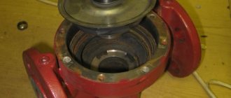
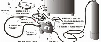
Holder repair and cable replacement
To repair the holder, simply unscrew the clamping bolts. After this, you need to get rid of the old piece of cable, strip the end of the new one and securely tighten it with bolts.
By the way, many people immediately want to change their old welding cables, but do not know which ones to choose. The cable for the welding machine must be durable to withstand shock and mechanical damage. It must also be resistant to aggressive chemical environments.
It is better to choose welding cables that will be able to withstand repeated winding and unwinding. In addition, the cable cross-section must be selected correctly to withstand the current load of the welding inverter.
The welding cable is marked with letters and numbers. KS - welding cable. T - resistant to elevated temperatures. KH - to the cold. You can work with this cable at a temperature of -60 degrees.
In addition, the cross-section of welding cables must be selected in such a way that the cables can withstand the load:
- For 100A welding inverters, the cable cross-section must be at least 6 mm²;
- For welding inverters over 100A, the cable cross-section must be at least 10 mm².
The most popular cross-section of welding cables is 16-25 mm. Such a cable can withstand welding currents of more than 180-200 Amps.
Choice of electrolytes from Hitachi, Samwha, Yageo
On the electronics market today you can find a large number of suitable capacitors from well-known and little-known manufacturers. When choosing equipment, one should not forget that with similar parameters, capacitors differ greatly in quality and reliability. The most well-proven products are from such world-famous manufacturers of high-quality aluminum capacitors as Hitachi, Samwha and Yageo. Companies are actively developing new technologies for the production of capacitors, so their products have better characteristics compared to competitors' products.
Aluminum electrolytic capacitors are available in several form factors:
- for mounting on a printed circuit board;
- with reinforced snap-in pins (Snap-In);
- with bolted terminals (Screw Terminal).
Tables 1, 2 and 3 present the series of the above manufacturers that are most optimal for use in the pre-rectification unit, and their appearance is shown in Figures 2, 3 and 4, respectively. The given series have a maximum service life (within the family of a particular manufacturer) and an extended temperature range.
Table 1. Electrolytic capacitors manufactured by Yageo
| Name | Capacity, µF | Voltage, V | Ripple current, A | Dimensions, mm | Form factor | Service life, h/°C |
| LV | 470, 560, 680 | 400, 450 | 1,70; 1,90; 2,10 | 35×40, 35×45, 35×50 | Snap-In | 3000/105 |
| L.C. | 470 | 400, 450 | 1,90; 2,10 | 35×45, 35×50 | Snap-In | 5000/105 |
| N.H. | 470…22000 | 400, 450, 500 | 2,4…39,4 | 51×80…89×270 | Screw Terminal | 5000/105 |
Table 2. Electrolytic capacitors manufactured by Samwha
| Name | Capacity, µF | Voltage, V | Ripple current, A | Dimensions, mm | Form factor | Service life, h/°C |
| HY | 470, 560 | 400, 450 | 1,91; 2,14 | 35×45; 35×50 | Snap-In | 7000/105 |
| JY | 470 | 400, 450 | 1,88 | 35×45 | Snap-In | 10000/105 |
| EY | 1500…10000 | 400, 450 | 6,1…24,3 | 51×110…89×160 | Screw Terminal | 7000/105 |
Table 3. Electrolytic capacitors manufactured by Hitachi
| Name | Capacity, µF | Voltage, V | Ripple current, A | Dimensions, mm | Form factor | Service life, h/°C |
| HP3 | 470…2100 | 400, 420, 450, 500 | 2,75…9,58 | 30×40, 35×35…40×110 | Snap-In | 6000/85 |
| HU3 | 470…1500 | 400, 420, 450, 500 | 2,17…4,32 | 35×45, 40×41…40×101 | Snap-In | 6000/105 |
| HL2 | 470…1000 | 400, 420, 450, 500 | 1,92…3,48 | 35×40, 30×50…35×80 | Snap-In | 12000/105 |
| GXA | 1000…12000 | 400, 450 | 4,5…29,7 | 51×75…90×236 | Screw Terminal | 12000/105 |
| GXR | 2700…11000 | 400, 450 | 8,3…34,2 | 64×100…90×178 | Screw Terminal | 12000/105 |
As can be seen from Tables 1, 2 and 3, the product range is quite wide, and the user has the opportunity to assemble a capacitor bank, the parameters of which will fully meet the requirements of the future welding inverter. The most reliable are Hitachi capacitors with a guaranteed service life of up to 12,000 hours, while competitors have this parameter up to 10,000 hours in Samwha JY series capacitors and up to 5,000 hours in Yageo LC, NF, NH series capacitors. True, this parameter does not indicate a guaranteed failure of the capacitor after the specified line. Here we mean only the time of use at maximum load and temperature. When used in a smaller temperature range, the service life will increase accordingly. After the specified period, it is also possible to reduce the capacity by 10% and increase losses by 10...13% when operating at maximum temperature.
We restore the operation of the welding inverter Resanta SAI-250PN
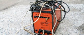
One day I came across a Resanta SAI 250PN welding inverter. The device, without a doubt, inspires respect.
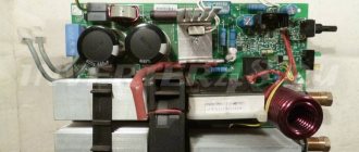
Those who are familiar with the design of welding inverters will appreciate all the power from the appearance of the electronic filling.
As already mentioned, the filling of the welding inverter is designed for high power. This can be seen from the power part of the device.
The input rectifier has two powerful diode bridges on the radiator, four electrolytic capacitors in the filter. The output rectifier is also fully equipped: 6 dual diodes, a massive choke at the rectifier output.
three ( ! ) soft start relays. Their contacts are connected in parallel to withstand the large current surge when welding is started.
If we compare this Resanta (Resanta SAI-250PN) and TELWIN Force 165, then Resanta will give it a head start.
But even this monster has an Achilles heel.
The device does not turn on;
The cooling cooler does not work;
There is no indication on the control panel.
After a quick inspection, it turned out that the input rectifier (diode bridges) were in good condition, the output was about 310 volts. Therefore, the problem is not in the power part, but in the control circuits.
An external inspection revealed three burnt-out SMD resistors. One in the gate circuit of the 4N90C field-effect transistor at 47 Ohms (marked - 470 ), and two at 2.4 Ohms ( 2R4 ) - connected in parallel - in the source circuit of the same transistor.
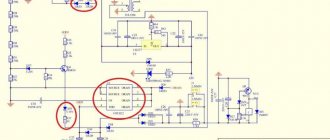
The 4N90C transistor ( FQP4N90C ) is controlled by the UC3842BN . This microcircuit is the heart of a switching power supply, which powers the soft start relay and the +15V integrated stabilizer. It, in turn, powers the entire circuit, which controls the key transistors in the inverter. Here is a piece of the Resanta SAI-250PN diagram.
It was also discovered that the resistor in the power supply circuit of the PHI controller UC3842BN (U1) was also broken. In the diagram it is designated as R010 ( 22 Ohm , 2W ). On the printed circuit board it has the position designation R041. I will warn you right away that it is quite difficult to detect a break in this resistor during external inspection. A crack and characteristic burns may be on the side of the resistor that faces the board. This was the case in my case.
Apparently, the cause of the malfunction was the failure of the UC3842BN (U1) PHI controller. This in turn led to an increase in current consumption, and resistor R010 burned out from a sudden overload. SMD resistors in the circuits of the MOSFET transistor FQP4N90C played the role of a fuse and, most likely, thanks to them the transistor remained intact.
As you can see, the entire switching power supply on the UC3842BN (U1) has failed. And it powers all the main blocks of the welding inverter. Including the soft start relay. Therefore, the welding did not show any “signs of life.”
As a result, we have a bunch of “small things” that need to be replaced in order to revive the unit.
After replacing the indicated elements, the welding inverter turned on, the value of the set current appeared on the display, and the cooling cooler began to make a noise.
For those who want to independently study the design of a welding inverter, here is a complete schematic diagram of the Resanta SAI-250PN.
Diagnosis of breakdowns of inverter welding machines
Smoke coming from the inverter housing or a subtle burning smell indicates a serious malfunction. In this case, it is not advisable to diagnose the equipment yourself. It is advisable to contact a service center so as not to aggravate the situation. Troubleshooting requires extensive experience in repairing welding machines and an understanding of all the nuances of the operation of this model.
When the malfunction is not so critical, you can diagnose it yourself. At the first stage, you need to remove the case and visually check all components of the device. Sometimes models with poor-quality soldering or poorly insulated wiring end up on the market. For repairs, it will be enough to re-solder some of the elements to restore the functionality of the equipment.
It is not difficult to understand which part has failed. It will be distinguished by the presence of darkened areas, have cracks or obvious signs of a short circuit. The rejected element should be replaced. Each part is marked, which will allow you to accurately select a similar one for replacement.
After a visual inspection that did not help identify problems, you can move on to a more thorough analysis. You will need a multimeter. With its help, all components of the board are checked. Transistors and printed conductors must be diagnosed. Burnt areas or broken circuits must be repaired. At the same time, all contacts on the board are checked. If required, they are cleaned with an ordinary office eraser.
The diode bridges of the inverter perform the functions of a rectifier. They are on the radiator. Diode bridges are characterized by reliability, but sometimes even they fail. To determine the serviceability of this node, it is necessary to remove it from the general circuit. Checking with a multimeter will give you an understanding of whether the diode bridge is working or not.
If after all the above manipulations you cannot find a breakdown, you should contact a specialist. It is not recommended to repair the welding machine yourself.