is engaged in the design of dies, technological equipment, as well as the production of dies. We produce stamps for:
- punching, cutting, stripping;
- bending, forming, drawing;
- automatic stamping.
For the manufacture of metal parts, special stamping tools are used, which greatly facilitate production. But it is extremely important to properly design and manufacture such devices in order to ensure increased accuracy and quality of stamping of products.
Design of a die for sheet metal stamping, selection of equipment
Volumetric stamping is a metal forming process that involves deforming a workpiece, resulting in metal filling the tool cavity - a die, called a groove.
Manufacturing of RES parts using powder metallurgy and pressure methods
2.2.1. Separation operations of sheet stamping
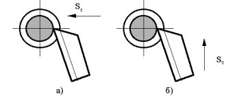
Cutting is the separation of a part of the material along an open contour with scissors or in stamps. Shears for cutting sheet material are parallel, guillotine, roller, disk and vibrating (Fig. 9.1). Parallel…
Forging and stamping of products
4.1 DESIGN OF THE KGSHP DIE
The dies of crank hot stamping presses have a prefabricated design, which simplifies the production of replaceable tools and creates conditions for saving expensive tool steels. Dies consist of die inserts...
Increasing the technical performance of stamping the “Piston” part by reducing the number of technological transitions and operations, increasing metal savings
f2. Selection and justification of technological process options for sheet stamping of parts
According to the basic technology, the “Piston” part is manufactured using the following technological process:
- 1. Cutting the sheet into strips;
- 2. Control;
- 3. Varnishing;
- 4. Felling;
- 5.Vacquering;
- 6. First hood;
- 7. Firing;
- 8. Hardening;
- 9. Locksmith;
- 10.Vacquering;
Development and technological process of manufacturing the “lid” part
3.3 Obtaining the initial blank for cold sheet stamping
The initial blank for this part will be a sheet 10mm thick. Rolled sheets are produced at rolling mills. The essence of rolling production is that the metal is plastically deformed by rotating rolls...
Development and technological process of manufacturing the “lid” part
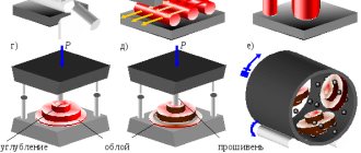
3.4 Description of equipment and tools for cold sheet forming
For cold sheet metal stamping equipment, a die with a spring buffer should be used to ensure constant force. The figure shows a diagram of the stamp and a sketch of the workpiece. Figure 5 4…
Development of technology and equipment for manufacturing the “Plank” part
f1. Analysis of the constructability of the form and the manufacturability of the manufacture of part elements using sheet stamping operations
Manufacturability should be understood as such a combination of structural elements that ensures the simplest and most economical production of parts while observing the technology and operational requirements for them...
Development of a technological process for sheet stamping of a lid and design of a die
f2. Die design, equipment selection
Development of a technological process for sheet stamping of a lid and design of a die
f2.4 Die design, sequence of die production and assembly
technological stamping press pressure Selection of stamp parts. Based on the dimensions of the working area, we select the overall dimensions of the matrix and calculate its thickness using empirical formulas. Using the obtained matrix dimensions...
Development of a technological process for processing the “Lid” part
2.2.1 Obtaining the initial blank for cold sheet stamping
The initial blank for this part will be a sheet 10mm thick. Rolled sheets are produced at rolling mills. The essence of rolling production is that the metal is plastically deformed by rotating rolls...
Development of a technological process for processing the “Lid” part
Description of equipment and tools for cold sheet stamping
For cold sheet metal stamping equipment, a die with a spring buffer should be used to ensure constant force. The figure shows a diagram of the stamp and a sketch of the workpiece...
Development of a universal machine for cutting, creasing and perforating paper
1.2 Features of the equipment and process of creasing sheet products
Creasing is the operation of applying a straight groove to a sheet of paper. It is necessary for subsequent folding along the line of paper with a density of more than 175 g/m² or cardboard. The groove itself is called big. Creasing is performed...
Technological process for manufacturing round broaches
f6. Design of operations, selection of bases and equipment
Operations design is the materialization of cost-effective processing methods. The choice of equipment is carried out taking into account the type of production. We select technological bases...
Technological process of assembling the die matrix of cold die forging of the VAZ 2108 internal hinge body
f1 technological process of assembling the die matrix of cold die forging of the body of the internal hinge of the VAZ 2108
Sheet stamping technology
f4. Mechanization and automation of the sheet stamping process
Stamping streams
Forgings of simple configuration are stamped from rolled steel of the desired shape - circle, rectangle, square. When a forging has a complex shape, the original workpiece is made as similar as possible to it by stamping or open forging. For such multi-level operations, as a rule, multi-strand dies are used for sequential deformation of the workpiece (shaping).
The stamping technology often occurs in several transitions.
This requires the use of the main types of streams:
- stamping;
- procurement;
- bran stream (knife).
The knife is applicable in the case of sequential stamping of a number of forgings from a rod. The finished forging must be cut from the bar using a cutting knife.
When hot stamping steel products, stamping strands are used.
They are divided into several types:
- lingering;
- pinch;
- procurement;
- bending;
- rolling.
Broachers lengthen a certain section of the workpiece.
Pinchers are used to increase the width of a certain section of the workpiece and reduce its height.
Blank stamping strands make it possible to redistribute the metal to the workpiece in such a way that the manufactured product takes shape with minimal waste of material.
In bending strands, a forging with a bending angle of 90° is formed from a workpiece with an offset axis.
The purpose of rolling stamping grooves is to uniformly distribute the metal along the axis of the workpiece, increasing the diameter of certain sections of it.
Stamping streams are also divided into rough and finishing products.
Rough bars include blanks whose shape is closest to the configuration of the forging. The rough stream has greater depth and increased slopes and rounding radii relative to the finished product.
This is necessary so that the rough blank fits into the final engraving. If stamping is performed, this step should be skipped.
In finishing streams, the product takes on a cone-like shape. The size of the part in the finishing stream is larger by the amount of shrinkage when the metal cools. The finishing stream is placed in the central part of the die due to the high forces exerted on the workpiece.
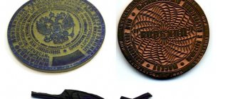
LASER TECHNOLOGY
Using laser engraving, stamps are created from rubber. Laser engraving allows you to obtain products that have maximum protection against counterfeiting. The pattern is applied to the rubber surface using a laser beam. This method guarantees high quality image reproduction. The product does not absorb ink, resulting in a clear and attractive print. Printing is low cost and durable.
Advantages:
1.High quality cliche printing.
When using the laser engraving method, it is possible to achieve ultra-high resolution - up to 2540 dpi and use additional degrees of protection against counterfeiting of seals - microtext, raster fields, etc.
2. Possibility of producing a stamp seal.
Laser equipment allows us to produce official stamps in accordance with GOST requirements.
3. Long service life.
A cliche made of rubber using laser engraving has a long service life due to the material’s resistance to aggressive chemicals and mechanical stress.
4. High production speed.
Laser engravers make it possible to produce several dozen cliches (depending on the size of the rubber and the cliches themselves), due to which a relatively high production speed is achieved, which allows us to offer a service - urgent production of seals and stamps .
INTRODUCTION
workpiece stamping fasteners cutting
Cold stamping is a type of metal forming that combines a number of processes carried out by cold plastic deformation using various types of dies that directly deform the metal and perform the required operations.
Technologically, cold stamping allows:
— to obtain parts of complex shapes, the production of which is very difficult by other methods;
— create parts that are strong and rigid, but lightweight in terms of their mass characteristics, with little material consumption;
— obtain interchangeable parts with high dimensional accuracy.
Economically, the advantages are:
- economical use of material and low waste;
— low cost of manufacturing products;
- high performance.
The development of the technological process for sheet stamping will be carried out using the KOMPAS-Stamp computer-aided design system, which is implemented in the Windows environment with the KOMPAS-Graph drawing and design editor. The KOMPAS-Stamp system is focused on automating the design of dies for various cold sheet stamping operations and provides automation of the design of dies of original and standard designs.
Equipment used
Even if the material being processed has a soft structure, the use of equipment to give it a given shape is mandatory. This equipment includes:
- Hydraulic presses.
- Guillotines.
- Crank mechanisms.
You also need to correctly calculate the consumption of materials and make drawings, taking into account the requirements of state standards.
If we consider a stamping machine, then it includes the following structural elements:
- an actuator corresponding to the type of machine;
- motor for driving equipment;
- transmission that provides movement from one mechanism to another.
Video: hot metal stamping - automated lines.
Sheet stamping
Since ancient times, people have made thin-walled products, vessels and jewelry from metal. They were made from a sheet of metal by hammering - giving shape to a cold or heated sheet of ductile metal by tapping it with a hammer around a wooden model of the future product. The seams were soldered or embossed. Copper was most often subjected to this treatment, less often silver or gold. The products obtained in this way were extremely highly valued, since all operations were manual and it took the craftsman more than one day to make one jug.
Sheet stamping
The inquisitive human mind was looking for ways to speed up and reduce the cost of production until the mid-19th century, when such a powerful source of energy as steam appeared. Since then, the technology for producing thin-walled metal sheet products by deforming it under pressure, or sheet stamping, has improved significantly. Today, billions of different parts are produced using this method, from phone parts to car bodies.
Materials used and their characteristics
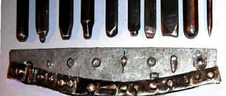
The following are currently used for the manufacture of stamps:
- magnesium is a metal of low hardness, silvery in color. Magnesium dies are relatively cheap products. Their circulation resistance is low; with flat foil stamping on paper, it does not exceed 100 thousand impressions. Magnesium can be processed equally well by etching (Fig. 1) and engraving;
- Copper is a very hard metal with a rose-red color. The cost of copper stamps is much higher than magnesium ones, but the circulation resistance is an order of magnitude greater (hundreds of thousands of impressions). Copper is difficult to engrave, so it is mainly processed by etching - usually etched to a depth of no more than 1 mm, therefore, to deepen the relief, additional engraving is required along the edges of the image - fig. 2 [5];
- brass is an alloy of copper and zinc, often with small additions of other elements. It has a yellow color reminiscent of gold. As a rule, it is processed by engraving. Due to the ease of machining, brass can be used in the manufacture of dies for multi-level embossing. The circulation resistance of brass stamps is hundreds of thousands of impressions (Fig. 3). Due to the complexity of manufacturing, brass dies are more expensive than copper and magnesium dies [5]. To increase the circulation resistance of brass dies, nickel plating is sometimes used;
- steel is a hard silver-white metal, which is an alloy of iron (base) with carbon (up to 1.7%) and other impurities. Steel stamps are used extremely rarely in modern printing. They are usually made by engraving, sometimes pre-etched (to save time). Steel engraving is carried out only on machines with a powerful spindle and requires a lot of time. Such stamps are used when embossing very large print runs (more than a million prints), since they are very expensive [6];
- polymers are the cheapest type of material compared to all others. They have different chemical composition, color, physical and mechanical properties. For the manufacture of stamps, polymer materials such as polycarbonate, getinax, various types of photopolymers, etc. are used. Some of the polymer stamps are transparent (see Figures 4 and 5). Polymer stamps are made by photopolymerization (see Fig. 4), engraving (see Fig. 5), and less often - by hot pressing. At the same time, their circulation resistance reaches hundreds of thousands of prints.
Rice. 1. Magnesium hot foil stamping stamp made by etching
Rice. 2. Copper hot foil stamp made by etching with additional engraving on the edges
Rice. 3. Brass hot stamping foil stamp made by engraving
Rice. 4. Photopolymer stamp for single-level cold embossing, made by photopolymerization
Rice. 5. Polycarbonate stamp for single-level cold embossing, made by engraving
Advantages and disadvantages of the process
Hot stamping has some advantages and disadvantages relative to forging.
Advantages of GOSH:
- high productivity exceeds forging hundreds of times;
- production of finished products of complex configuration;
- relative simplicity of a specialist’s work and faster training in the necessary skills;
- fewer tolerances and allowances, since only the contacting surfaces of the parts are machined, and the remaining surfaces have satisfactory geometric parameters and roughness. After calibration, tolerances are only 0.05 mm.
The disadvantages are:
- the weight of the finished product does not exceed 3.5 tons;
- the high cost of a special die tool in contrast to a forging tool. The die is made on the basis of high-quality steel and is used exclusively for a certain size of forging;
- the need to use more powerful equipment due to the deformation of the entire workpiece, and not part of it, which requires an increase in the impact force. And also the walls of the die cavity experience pressure during the flow of metal, which affects its wear resistance.
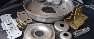
Design and production of dies
One of the company's activities is the design and production of dies, molds and technological equipment. PF "Delfa Service" offers design services for cold sheet metal
, including large dies for automotive body parts.
Designing stamps begins with you providing initial information, which can be in the form of:
• mathematical model of the part imported from any 3D CAD system;
• drawing of the part - in this case, our specialists will build a three-dimensional model of it;
• sample part
Based on the information received, we offer stamp manufacturing
, molds and repair of products manufactured by us. When developing a die design, the company places high demands on manufacturability, durability, strength, and reliability of the die design and part fastening. And the ability to quickly replace a worn part, conveniently load a workpiece into a die and easily remove waste will ensure safe operation and cost-effective production of parts.
Our company designs and manufactures all types of cold stamping dies:
– dies for cutting, punching, notching, trimming, stripping,
– dies for bending, forming, drawing, die forging,
– multi-position dies, combined,
– dies for automatic metal stamping on stamping complexes.
Our advantages
Modern metalworking equipment is used in the manufacture of dies and molds. We produce dies for cutting, drawing, and bending of any complexity. Mold making
and stamps takes a minimum amount of time, since our company has the ability to carry out a full range of work in its own production , which significantly reduces the time from the customer’s application to the final testing of the stamps, or until receiving a batch of stamped parts according to the drawing.
Designs of cold metal stamping
and their parts are diverse (Separating, Shaping, Relief-molding, straightening, embossing, Combined), and the cost of the part depends on the correctness and accuracy of their production. Our company is ready to accept your order for the design and manufacture of dies and molds according to your technological requirements.
Features of GCM
A horizontal forging machine (HFM) has dies consisting of a split engraving. The engraving has three parts: fixed, movable (clamping) and a punch with a connector in planes perpendicular to each other.
Metal reinforcement with a round or square cross-section is inserted into a stationary matrix, the movable matrix presses it, after which the punch deforms the workpiece, pressing it into the forming cavity.
After the deformation procedure, the dies are unclenched, the workpiece of the desired shape is pulled out, or it falls out on its own. The final result is achieved through several crossings in different streams. Due to the fact that the die has three working parts, the slopes and overlaps on the forgings are minimal or absent altogether. GCMs are characterized by low versatility and high cost.
Hot stamping has found its application in such industries as mechanical engineering, as well as in other industries that require the creation of complex parts made of steel, non-ferrous metals and their alloys.
DIES FOR COLD STAMPING. TYPICAL UNITS AND PARTS
Most dies have a certain number of standard parts that are similar in purpose and design.
To simplify the design, manufacture, operation, and repair of die equipment, standard units and parts are normalized. Normalization reduces the number of worn-out stamp parts , expands the possibilities of interchangeability of parts, reduces the need for the number of stamps used in production , increases the reliability of their operation, and reduces the cost of stamping equipment. when developing dies, manufacturing and repairing them . The development of a set of mechanical engineering standards for stamping equipment has made it possible to sharply reduce the range of components and parts of dies and to produce dies in which up to 80% of the parts are normalized. The most widely used types of assemblies and parts of dies for cold stamping (provided for by mechanical engineering standards): DIE BLOCKS Die blocks are sets of upper plates and lower die bases connected by guide devices (columns, strips).
- with two guide columns,
- with diagonal column arrangement
- rear or axial arrangement of speakers
For stamping large, complex and precise parts, die blocks are made on three and four columns. To regrind the die without disassembly, die blocks with counter-pressing of the columns - one column is pressed into the lower plate, the other into the upper one. For work in large-scale and mass production on high-speed presses, universal die blocks for separating dies on columns with ball guides. Compared to sliding guides, ball guides have an easier movement, they do not heat up at high stamping speeds, they hardly wear out and provide greater directional accuracy. Ball guides, after being lubricated during assembly of the block, do not require additional lubrication for several months of operation. The lower and upper plates of the die blocks are cast from cast iron or steel. The guide columns and die bushings are made of low-carbon steel, case-hardened and hardened. To ensure independence and accuracy of the stamp operation from the condition of the press slide guides, in stamp blocks with ball guides, a shank with a “floating” fastening to the top plate is used. Die packages are upper and lower sets of die parts. They consist of rectangular (or round) steel plates that carry a punch, die, puller and other parts. Stamp packages are stamp blanks. Selected according to the size of the parts, they make it possible to quickly create any stamp based on a normalized block, making a punch, a matrix and a puller of the desired profile for it. Packages of dividing dies: cutting, punching, sequential action and the like are manufactured with fixed pullers and with an upper clamp. SHANKS FOR DIES. For regular and block dies intended for separation operations, standard shanks with a collar are used. This type of shank is pressed into a pre-bored hole in the top plate. For dies with special die centering accuracy , the shank, after being pressed into the plate, is additionally ground in assembled form. For drawing and bending dies with guide columns, threaded shanks , and in large dies, threaded shanks with a shoulder are used. In large dies with guide columns, where the shank is used for central installation, or in dies where, for design reasons, other types of shanks cannot be used, special shank designs are used. For screw fastening of the punch of drawing dies, shanks with fastening of the punch in the shank are used. When cutting thin-sheet materials during fine and precise stamping in cutting dies of combined action and in dies with carbide punches and dies , as well as in die blocks with ball guides, self-aligning (“floating”) shanks with a spherical liner are used. For heavy duty work in bending dies, fork shanks are used. When installing dies on presses that have different hole sizes in the slide for the die shank , adapter shanks or adapter split bushings are used. PUNCHES FOR DIES. Cold forming dies use standard punches of various types.
- Shape: round and profile
- by design - solid and composite,
- according to the method of fastening in the upper plate of the die - non-separable and quick-change.
Non-separable punches are secured by pressing into the upper plate of the die with subsequent riveting of the non-working end or using a collar on the non-working end. Both the riveting and the shoulder are necessary to hold the punch in the top plate of the die during the reverse stroke of the press ram. Quick-change punches have a cylindrical non-working part and are secured with a ball that fits into the punch recess. They are replaced without removing the stamp from the press. Profile punches are secured by riveting the non-working part or using screws and pins. In Fig. 65, a-k show the main types of round and profile punches. Round punches of type A, held by a riveting head, are used for punching holes with a diameter of up to 12 mm, especially when several punching punches are located close together, when retention by a shoulder cannot be used of type B, held by a shoulder, is used for punching holes. The cylindrical extension part k of these punches is designed to fit into the hole of the die guide plate. A type B punch with a collar is designed for punching large holes and cutting out parts along the contour. When the punch diameter is more than 45 mm, a recess is made at its end to reduce the grinding surface during sharpening. The type G punch is quick-change, held by a ball with a spring. A punch is used when punching a large number of holes in material up to 3 mm thick. Replacement is carried out by pressing the ball through the hole. A punch of a similar design (type D) is used for heavy punching work and in large dies. The ball is held in place by a pressure screw. Profile punches come in four main types. The type e punch, held by a rivet, is used for cutting out small and medium-sized profile parts. To cut out parts of medium size and complex shapes, type Z punches are made, having a flange with which they are attached to the top plate of the die with screws and pins. The type 3 punch consists of two parts: the working part and the insert. It is used to save tool steel when cutting parts of large dimensions, but of simple configuration. Composite punch type is used for cutting out parts of large dimensions and complex configurations. It consists of separate cutting sections fitted to each other and mounted on the top plate of the die. The sections are secured with screws and pins. For punches with a complex working profile of type K, a landing part of a simple shape is provided. The largest dimensions of the landing part must coincide with the overall dimensions of the working contour of the punch. MATRIXES FOR STAMPS. In dies for cold stamping, standard dies are used :
- by design - solid and composite,
- in shape - round, rectangular or profile,
- according to the method of fastening - non-removable or quick-change.
Non-separable matrices are secured by pressing or screwing to the plate with screws (bolts). Quick-change dies are secured with screws or a ball. The common design and technological element of the matrices of cutting and punching dies is the shape of their working profile. Type A round cutting dies are used for cutting round workpieces. For simple, sequential and combined cutting (or punching) of medium-sized parts, type B dies are the most common. When cutting out parts of complex shapes, cutting out large parts or small-width parts with large lengths and sharp corners, type B split dies are used. Cutting the matrix facilitates its production and finishing, and eliminates warping during hardening. For cutting out parts of large dimensions and complex shapes, composite dies of type g are used, consisting of separate sections fitted to each other and mounted on the bottom plate of the die. Work on such matrices is carried out with reverse ejection of the cut-out part. Punching dies for multi-punch dies are most often made in the form of replaceable cylindrical inserts. Smooth matrices (type d) and matrices with a collar (type e) are secured by pressing into the matrix plate. They are used only for punching round holes. Quick-change cylindrical dies (type g), held by a ball with a pressure screw, are used for holes with a diameter of up to 30 mm. The profile elements of the working hole of the matrix are selected depending on the thickness of the stamped material. When punching several closely spaced holes with a diameter of up to 8 mm, matrices with a profile of type Z are used. The same holes are made for cutting out simple contours (type l). For matrices with a figured contour, a hole shape of type i or m is used. A profile of type k with an increased height of the working conical hole or with a cone along the entire height is used for matrices of increased durability with small part sizes. For dies with reverse ejection of parts (mainly in combined-action dies), a profile of type n is used. PULLERS FOR DIES. Depending on the design of the die , the size of the punch, and the thickness of the material being stamped, punching and punching die removers may be designed to remove parts, to remove strip waste from punches, or to give precise guidance to punches. The exact direction of the punch in the puller is necessary to ensure that the gap between the die and the punch is uniform on all sides. In this case, the gap between the punch and the puller should be no more than the gap between the punch and the matrix and is usually taken equal to 0.8 of the latter’s value. Fixed and movable pullers are used. Fixed pullers are used in punching dies working from a strip to fail, and in punching dies, if during stamping it is not necessary to press the workpiece against the die and if the puller itself does not interfere with inserting the workpiece into the die and removing the part from the die. When it is necessary to give direction to the punch, only stationary pullers are used. Precise direction of the punch in the puller is recommended for use in dies that do not have guide columns, in multi-punch dies with different punch sizes, in dies with thin punches and in dies with a top clamp. In movable pullers, the movement and the necessary clamping force are provided by springs, rubber buffers or pneumatic and mechanical devices of dies and presses. Movable pullers are used in combined dies of combined action and with an upper clamp. The puller shown in diagram d is also a clamp for the part and at the same time a clamp for the internal contour of the part. Diagrams f, g, h, and show various design options for movable pullers. GUIDE BARS FOR DIES. The slats impart direction to the strip (tape) as it moves. If it is necessary to press the strip to one side of the guide bar, side clamps are mounted along with the bar. The gaps between the walls of the guide bars and the strip are important, as they determine the accuracy of the material being directed into the die. The size of the gap depends on the width of the strip at a certain thickness and ranges from 0.5 mm (with a width of up to 50 mm and a thickness of up to 1 mm) to 2.5 mm (with a width of more than 200 mm and a thickness of more than 5 mm). For stamps with step knives, the distance between the slats is determined by calculation taking into account the width of the part of the material cut by the knives. On the exit side of the strip, the distance between the guide bars is taken equal to the distance between the stepping knives. For stamping parts from thin materials, elongated guide bars are used, equipped with a device for pressing the strip or tape as it moves between the walls of the bars. STOPS FOR DIES. The stops are designed to limit the feed of the strip into the die. The main types of stops: Type a - permanent mushroom stop is used in dies with a fixed puller when manually feeding material; type b - constant hook-shaped - has the same purpose, but is used in cases where the seating part of the stop needs to be removed from the cutting edge of the matrix. For combined-action dies, “sinking” stops with a spring or stops with a rubber liner are used. In cutting dies with a fixed puller, when cutting out narrow parts (from 6 to 20 mm) with a thickness of at least 0.8 mm, spring movable return stops of type B are used. For sequential action dies, when installing the strip on the first pass, preliminary side clamps are made with or without a spring. Cutting dies and combined dies of sequential action when stamping small and medium-sized parts from material with a thickness of more than 0.5 mm are equipped with automatic stops. This stop is connected to the upper plate of the die and is driven by the working stroke of the press slide. Catchers. In combined sequential action dies, the final position of the strip after punching the first hole is fixed by catchers, which eliminate feed errors and ensure the correct position of the punched holes. CATCHERS AND RETAINERS FOR DIES. Catchers and clamps:
- round catchers for different hole diameters,
- pin retainer,
- strip retainer
For multi-row stamping, two catchers are installed. The entry (catching) part of the catcher must have a pointed shape, and the fixing part must be cylindrical, square or profile in accordance with the shape of the hole of the stamped part. Retainers. To fix previously cut workpieces, various clamps are used, the design of which depends on the shape of the workpiece. Methods of fixation are used along the outer contour of the workpiece and along the contour of the hole. In some cases, workpieces are fixed, as indicated earlier, using technological holes specially punched for this purpose. WEDGE DEVICES FOR DIES. Wedge devices. In multi-operational dies, wedge punching devices are used to punch holes in the side walls of hollow or bent parts, allowing one or more holes to be punched or punching to be performed simultaneously with other operations. Wedge devices are also used in dies when it is necessary to bend the side flanges of flanged parts.
About die patterns
► Two hot stamping schemes are used in the production process:
- Closed type - according to the given technology, small gaps are visible between the stationary and movable parts of the stamp and are minimal. To produce products, presses are used with a protrusion at the top of the working tool, and a cavity at the bottom. Or, on the contrary, on hammers with a protrusion from below, in a cavity in the upper part of the tool used. This method is used when the volumes of the finished product and the forging correspond to the parameters. Stamps of this type simultaneously have two cavities for the connector, located at an angle of 900 relative to each other.
- Open type - the principle of their operation is based on the fact that a gap is provided between the fixed and moving parts into which excess metal is poured. They can be used for forgings of any size.
► Advantages of production using open type dies:
- Impeccable surface quality.
- Homogeneous material structure.
- Metal saving.
- The possibility of using materials with low ductility, as high stress is applied and unevenness during compression is ensured.