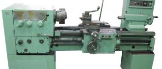
Before the collapse of the USSR, the 15u04p lathe was manufactured on the territory of Armenia; Soviet engineers used it in educational institutions, where during training it was necessary to conduct practical classes on the instrument itself. Over time, due to the ease of operation, this metal cutting machine began to be used in repair shops. To become more familiar with this model, you need to study the characteristics and purposes of the device.
Its processing accuracy corresponds to class “P”, the power of the device is 0.8, the 1972 series has small dimensions with a weight of 540. Some are distrustful of this series, but professionals unanimously say that when comparing it with other models of this class, purchase the device costs. It is not untested equipment that has recently come into production. Over the decades in the metal processing industry, its popularity has only increased.
Manufacturer information
The Armenian city of Kirovkan was the second largest in the number of industrial enterprises in the republic. Among the leading ones was the plant of precision machine tools - KZPS. It produced high-precision equipment, including CNC and laser machines. They received numerous prizes. At the international fairs in Plovdiv and Leipzig, Kirovok products received gold medals.
In 1988, during an earthquake, the KZPS was completely destroyed. Many workers died. After this, the workshops were never restored. The 16U series teaching machines are no longer in production, but they were produced in the last century and continue to work. Read also: lathe DIP-500 its features and technical characteristics.
Purpose and scope
Precision screw-cutting lathe - increased accuracy, machine 16U04P was intended for training young people in vocational schools, schools and technical schools. High processing accuracy and small dimensions made it possible to use the equipment in laboratories and repair shops.
The following operations are performed on a screw-cutting lathe 16U04P:
- rough processing;
- fine turning along the axis;
- trimming ends;
- cutting metric, inch and pitch threads;
- processing of external cones;
- drilling and boring ends.
The purpose of 16U04P is the production of turning works, the production of single parts with high precision.
16U03P, 16U04P characteristics
The technical characteristics of screw-cutting lathes models 16U03P, 16U04P allow for high-precision turning operations, including processing of metal workpieces in chucks, collets and centers.
| Name of parameters | 1525 | 1L532 |
| Maximum processed diameter, mm | 2500 | 3150 |
| Maximum height of the installed product, mm | 1600 | 1600 |
| The largest mass of the installed product depending on the number of revolutions per minute of the faceplate, kg: | ||
| from 1.25 to 40 rpm | — | 16000 |
| from 1.6 to 50 rpm | 16000 | — |
| 50 to 63 rpm | — | 9000 |
| from 63 to 80 rpm | 8000 | — |
| Number of vertical non-turret supports | 2 | 2 |
| The largest cross-sectional dimensions of the cutter holder (width x height), mm | 40x63 | 40x63 |
| Vertical non-revolving support | ||
| Maximum movement, mm: | ||
| Horizontal | 1390 | 1720 |
| Vertical | 1200 | 1200 |
| Dial division price, mm: | ||
| horizontal movement | 0,05 | 0,05 |
| vertical movement | 0,05 | 0,05 |
| Movement per one revolution of the dial, mm: | ||
| Horizontal | 2,5 | 2,5 |
| Vertical | 2,5 | 2,5 |
| Speed of installation movements, mm/min | 5…1800 | 5…1800 |
| Maximum rotation angle of the caliper slider | 30° | 30° |
| Caliper slider rotation scale division price | 1° | 1° |
| Caliper slider rotation dial division price | 1’ | 1’ |
| Caliper installation movements | available | available |
| Remote switching on, switching and switching off working feeds | available | available |
| Switching stops: | ||
| horizontal movement | available | available |
| vertical movement | available | available |
| Cross member | ||
| Maximum displacement, mm | 1240 | 1240 |
| Travel speed, mm/min | 360 | 360 |
| Switching stops | ||
| Movement and automatic clamping of the crossbar | available | available |
| Faceplate | ||
| Faceplate diameter, mm | 2240 | 2800 |
| T-Slot Dimensions | See Figure 1 | See Figure 1 |
| Remote switching of faceplate speeds | Available | Available |
| Working with stepwise constant cutting speed when turning end surfaces | Available | Available |
| Turning on the rotation of the faceplate “Push” | Available | Available |
| Blocking the rotation of the faceplate in the absence of lubrication | Available | Available |
| Braking | Available | Available |
| Dimensions and weight | ||
| Overall dimensions of the machine, mm: | ||
| length | 5065 | 5485 |
| width | 5340 | 6120 |
| height | 4910 | 4910 |
| Machine weight, kg | 35500 | 43000 |
Figure 1.2 - Working space of machines 16u03p (in the figure on the left); 16u04p (in the picture on the right):
I - sketch of the caliper; II - sketches of the end of the spindle; III - sketch of the tailstock quill
a - under the center; b - under the collet.
Specifications
According to the accuracy class, 16U04P machines belong to group P - precision. It processes parts with a diameter of up to 200 mm and a maximum length of 350 mm.
The spindle has a through hole. It allows you to use a rod with a diameter of up to 20 mm as a workpiece when it is fastened in a chuck, and rolled up to 10 mm when using a collet.
The spindle rotation speed is adjusted smoothly and steplessly. The maximum frequency of forward and reverse spindle rotation is 3500 rpm. There is no brake.
The caliper has a maximum movement:
- longitudinal – 350 mm;
- transverse – 135 mm.
One division of the dial is 0.025 mm with transverse feed. When moving along the axis of the part - 0.5 mm.
Important!
The cutting slide moves up to 120 mm and rotates 45⁰, which allows you to sharpen cones.
The tailstock quill with a diameter of 35 mm has a longitudinal movement of up to 70 mm. Morse hole taper 2.
The 0.8 kW electric motor rotates at 1370 rpm.
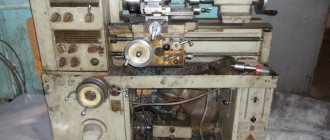
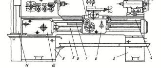
Location of main parts
The 16U04P screw-cutting lathe consists of large units:
- bed;
- headstock;
- tailstock;
- apron;
- sled;
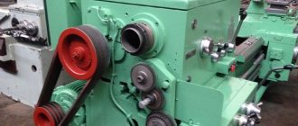
- variable speed drive;
- guitar;
- gearbox.
The main motor is mounted on a foundation below the headstock. The remaining components are mounted on the frame.
Rotation from the engine to the spindle is transmitted through a variator belt drive and gearbox gears. The control mechanism is located at the top of the body.
The headstock contains the spindle and the variator gearbox. They reduce the number of revolutions of the motor shaft and increase the power of the machine. Gears and bearings are splash lubricated.
A guitar is attached to the headstock on the left side. The feed speed is varied by installing gears with different numbers of teeth.
The apron is located below the headstock and protrudes beyond the frame. Due to rotation through the feed box, it drives the drive shaft and moves the caliper along the frame - the axis of the part. The screw is turned on to cut the thread. It provides a given cutter pitch - the ratio of revolutions and longitudinal movements.
The tailstock is on the right. It moves along the guides manually. The quill extends by rotating the handle at the end of the assembly.
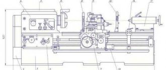
Location of components
The delivery set of the 16U04P screw-cutting lathe includes the machine itself and a massive stand for its installation. In its left part on the lower frame there is a variator, in the right there is a cabinet with electrical equipment, and between them there is a coolant tank and an electric pump. On the upper surface of the cabinet there is a tray for collecting chips and cutting fluid. The coolant is drained into the tank through the sump filter. On the front top of the cabinet there is a machine control panel, next to which there is a drawer for tools. The cabinet is attached to the concrete floor with five anchor bolts.
In terms of the composition of the basic components, 16U04P is similar to other representatives of the family of universal turning equipment:
- bed;
- drive with variator;
- headstock;
- caliper;
- gearbox;
- guitar;
- apron;
- tailstock.
The 16U04P bed is a massive cast iron structure, which is secured to the stand with bolts. The undoubted advantages of this machine include a large through window in the bed, through which turning chips and coolant can easily fall onto the pallet. On its upper surface there are two pairs of guides: wide prismatic in the center, and narrow at the edges: flat and trapezoidal.
If you need metal mesh for concrete reinforcement, we recommend that you pay attention to the production of road mesh.
Central guides: the front headstock is installed on the left, the tailstock is installed on the right, and the lower carriage of the caliper is installed on the outer ones. A guitar with a snaffle is mounted on the headstock - a mechanism for changing the direction of the lead screw and moving its neutral position, and below there is a feed box, from which the movement is transmitted through the lead screw and the lead shaft to the apron and then to the caliper. The 16U04P caliper is traditional, cross-shaped, with two carriages and a cutting slide.
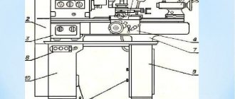
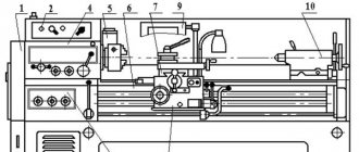
Location of controls
On the top of the headstock body there are switches for the pick and pull bit. Below are the longitudinal feed switch handles and the lead screw activation handle.
On the front panel of the feed box there are buttons: stop brake, start of forward and reverse rotation of the spindle. There is also a flywheel that regulates the speed of the chuck and the spindle with the variator handle.
On the apron are located:
- handwheel for manual transverse movement of the slide;
- button to turn it off;
- longitudinal feed switch handle;
- handle for manual movement of the caliper.
The light turns on on the lampshade. The tailstock controls are located on it.
Device
In addition to them, the mechanism itself consists of:
- The front beam, which regulates the work when cutting metal, helps control the movement of the drive and regulate the thread cutting process. This allows you to select the volume of metal boring, which is why it is called a high-precision screw cutting machine.
- Guitar attached to the front beam. It has replaceable gears on which cutters are located that control the processing process. If necessary, it is possible to install different gear options.
- Feed box attached to the front beam. With good precision adjustment, it allows you to obtain one processing step size, controlled by two handles.
- Apron. With its help, longitudinal movement of the caliper is carried out.
Due to its practicality and ease of carrying out various types of work, the device has become one of the most common among equipment associated with processing metal workpieces. In addition to the main advantages of this model, it is easy to repair and carry out the necessary procedures to improve the workflow and extend its service life.
In addition to all the advantages, this device has one more thing that cannot be ignored: its price. Compared to the prices of other similar devices, its price is more affordable for the buyer, and its practicality and efficiency are also excellent.
Electric scheme
The main electric motor runs on three-phase current with a voltage of 380/220 V. It drives the main operating units:
- rotates the spindle through the gearbox;
- moves the caliper and slide over the shaft and screw.
The motor is turned on and off on the front panel of the machine. When turned off - pressing the “Stop” button, the circuit opens, the current stops flowing to the winding and braking is activated.
From the main drive, through a step-down transformer, the machine lighting operates - a lamp on a flexible leg with a 36 V light bulb. It is installed on the back of the support and moves along the machine along with the cutter.
The second engine starts the lubrication and cooling system pumps. It turns on automatically when the equipment starts operating.
Electrical equipment has protection:
- zero on the starter coils;
- thermal overload relay;
- automatic circuit breakers and fuse links against short circuits.
Important!
All electrical equipment is connected to the ground loop.
Installation drawing
The area for installation of the machine has dimensions of 1350×505 mm. The length and width of the unit at the extreme protruding points (handles) are 1380 mm and 706 mm. There are 3 mounting bolts at a distance of 76 mm from the rear border. The first is at a distance of 76 mm from the left end under the headstock. The center-to-center distance between the rest is 437 and 750 mm.
There are 2 bolts in front on the headstock side at a distance of 351 from the fasteners located at the rear.
Instructions for use, passport
Before starting work on the 16U04P machine, you must read the Manual. After the requirements for packaging and transportation, it specifies the equipment and operating conditions:
- after each shift, remove chips, wipe and lubricate the guides;
- Oil changes are carried out monthly;
- cutters are installed in a cutter holder with a stem thickness of 10×10 mm and 12×12 mm;
- preventive inspections and replacement of wear parts every 6 months.
Screw-cutting lathes 16U04P are designed for processing steel and cast iron parts. Turning of wooden and plastic blanks is performed with a special tool in extreme cases.
You can download the machine's passport for free from the link - Passport of the lathe 16U04P.
Overall dimensions of the workspace
The area of possible processing of turning equipment is determined by the maximum capabilities of its mechanisms directly involved in the processes of positioning and turning, as well as components and assemblies that limit their capabilities. The maximum turning length during turning is determined by the maximum center-to-center distance. The 16U04P lathe was produced with two RMC options: 350 and 450 mm. The maximum turning diameter above the guides and carriage is the same for both options and is 200 and 118 mm, respectively, and the maximum stroke of the transverse slide is 133 mm.