Rollers are versatile equipment that allows you to effectively cope with sheet bending operations. Making rollers with your own hands is not so difficult, but to do this you need to first become familiar with the serial models, their design and principle of operation.
Three-roll hand rolls are the most suitable design for do-it-yourself production.
Information about the manufacturer of the three-roll plate bending machine IB2222
The manufacturer of the three-roll sheet bending machine IB2222 is the Slavgorod plant of forging and pressing equipment KPO named after the 8th anniversary of October .
The developer of the IB2222 sheet bending machine is the Azov Special Design Bureau of Forging Equipment and Automatic Lines, SKB Co.
Currently, the IB2222 machine is produced by PJSC Kuvandyksky, Orenburg region, Kuvandyk
Machine tools produced by the Slavgorod press-forging equipment plant KPO
- I2222
- three-roll sheet bending machine 2000 x 16.0 - IB2220
- three-roll sheet bending machine 2000 x 10.0 - IB2222
- three-roll sheet bending machine 2000 x 16.0 - IB2222V
- three-roll sheet bending machine 2000 x 16.0
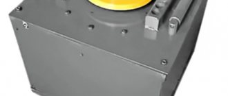
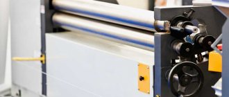
IB2222 General view of the three-roll sheet bending machine
Photo of three-roll plate bending machine IB2222
Photo of three-roll plate bending machine IB2222
Photo of three-roll plate bending machine IB2222
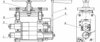
IB2222 Arrangement of components of a three-roll sheet bending machine
Location of the components of the sheet bending machine IB2222
Location of the components of the sheet bending machine IB2222
IB2222 List of components of a three-roll sheet bending machine
- Frame - IB2222-11-001
- Racks - IB2222-12-001
- Folding support - IB2222-14-001
- Device for bending conical shells - IB2222-15-001
- Main drive - IB2222-21-001
- Drive for adjusting the height of the side rolls - IB2222-22-001
- Tilt mechanism for tilt support - IB2222-23-001
- Upper roller - IB2222-31-001
- Side rollers - IB2222-32-001
- Fencing - IB2222-71-001
- Lubricant - IB2222-82-001
- Electrical equipment - IB2222-91-001
- Electrical cabinet - IB2222-92-001
- Control panel - IB2222-93-001
- * Front table - SSh6
- * Reception table - SP20
- * Product removal mechanism - MSI8
- * Shell support mechanism - MP01
- * Tool for bending corners, strips, squares, pipes, channels - IB2222-64-001
- Knee switch - IB2222-65-001
* For machines with mechanization means
IB2222 Control panel for three-roll plate bending machine
Control panel for three-roll plate bending machine IB2222
IB2222 List of roller controls
- General stop
- Control circuit switch
- Main drive rotation direction switch
- * Release button - forward
- * Button for turning on the removal mechanism - back
- Button for lifting the folding support
- Knob lowering buttons
- Button for switching the shell support mechanism up
- Button for switching the mechanism to support the shell down
- Rear side roller up button
- Rear side roller down button
- Front side roller up button
- Front side roller down button
- Signal lamp "Network"
- Signal lamp “Main drive is on”
* For machines with mechanization means
Note: On sheet bending machines, the control panel can be built into the main drive guard (IB2213, IB2216 machines) or be remote - attached to the knee switch brackets (IB2219, IB2220, IB2222 machines).
Three roll plate bending machine
Structure of a three-roll sheet bending machine
The purpose of three-roll sheet bending machines is to bend a cylindrical blank element from rolled sheet metal without the use of high temperatures. This industrial equipment is a modern, easily maintained machine tool with 3 symmetrically arranged rolls. The upward-downward movement of the upper roller, located symmetrically with respect to the axial direction of the other two roller wheels below, is carried out via a screw-nut transmission. Thanks to the high-torque drive, the sheet metal blanks are pushed through the lower rollers. The mobile control panel, which is equipped with the described machine tool, makes it possible to carry out production technical operations in comfortable and convenient conditions. About the main technical characteristics of the rolling machine. Among similar technical devices, it stands out favorably: Hydraulically driven rotational movements of the rolls in the center; Hydraulic drive of the rotational movement of the rolls on the side; Control by means of a hydraulic line of the folding support of the upper roll; control is carried out by the operator by setting commands on the control panel; A drive for inclined movement of the upper roll, which allows the removal of bent shells. The housings of these machine tools are welded structural bases. The frames, shafts and bearings used in the manufacture of these three-roll sheet bending machines are marked in compliance with European quality standards. The machines are manufactured in accordance with CE regulations and are manufactured with the required safety precautions regarding electronics and hydraulics. Among other things, it is possible to make an additional order for the purchase of a CNC system. Spherical roller bearings, when used, make it possible to completely stop the abrasion of shaft surfaces and, at the same time, lead to an improvement in the productive technical characteristics of a three-roll plate bending machine. About the standard version: — Technical device for bending cone-shaped products; — Shafts hardened by induction; — Availability of a digital display for monitoring the location of the shafts from the side; — High-strength steel body base of the machine tool; — Equipped with two operating speed modes; — Control panel, thanks to which you can control the folding supports on the shafts from above; — Carrying out control thanks to the control panel over the progress of movement and setting the parallel arrangement of shafts; — Equipping with such technical devices as a hydraulic motor and planetary gearbox, driving the shafts in the center; — Availability of a system that protects against overloads; — Equipped with a control panel; — Execution in accordance with CE normative data.
IB2222 Kinematic diagram of a three-roll sheet bending machine
Kinematic diagram of the sheet bending machine IB2222
- Electric motor for driving side rolls (M1) (main drive) - 12 kW
- Pulley – Ø200
- Pulley – Ø400
- Gearbox - Ts2U-315N-40-21
- Gear – m=16, z=18
- Gear – m=16, z=21, 2 pcs.
- Side roller – Ø260, 2 pcs.
- Speed control relay - no
- Electric motor for adjusting the height of the side rolls (M2.3) - 5.5 kW, 2 pcs.
- Coupling, 2 pcs.
- Pulley – Ø140, 2 pcs.
- Pulley – Ø180, 2 pcs.
- Gearbox - 4-125-31.5-56-3ts-U4, 4 pcs.
- Coupling, 2 pcs.
- Screw pair for lifting side roll - Tr86 x 10, 4 pcs.
- Lever, 4 pcs
- Top roller – Ø270
- Screw – Tr60 x 9
- Upper roll lift screw
- Folding upper roll support
- Electric motor of the tilting mechanism of the folding support of the upper roll (M4) - 1.1 kW
- Gearbox - 24-40-10-56-4-1-U1-1
- Screw pair - Tr32 x 6
- Retainer
- Spring
- Cup
- Shell support drive electric motor (M6) - 0.75 kW
- coupling
- Screw pair - Tr32 x 6
- Video clip
- Electric motor drive of the product removal mechanism (pusher) (M5) - 1.5 kW
- Gearbox - 4-100-50-52-1Ts-U4
- Drum – Ø150
- Screw
- Carriage
- Shoe brake - Tr-200
- Brake pulley – Ø200
- Pulley - no
- Pulley - no
- Block, 2 pcs
Manufacturing sequence of a manually driven rolling machine
It is best to use ready-made drawings for homemade rollers, which are available on specialized forums. If it is necessary to make a manual rolling machine for other parameters of the parts being produced, then the design begins with determining the force and torque required for bending. These values will be minimal in the case of deformation of aluminum grades AD0 or AD1, but with a workpiece thickness of up to 0.8 mm, low-carbon steel grades steel 08 or steel 08kp can also be bent. If the obtained values satisfy the physical capabilities of the performer, then we can move on from design to the manufacture of parts for future sheet bending rollers.
Installation of the upper roll of the rolling machine
To make a roller machine with your own hands, you first need a drawing of the general view of the machine, where you should depict the kinematic diagram of the movement of all its moving parts. You will also need drawings of assembly units and working drawings of non-standardized parts of a three-roll sheet bender. It is desirable that there be fewer such parts, since making many of them at home, and with your own hands, is difficult, if not impossible. In particular, it makes sense to find guides with a round cross-section, for example, from a decommissioned 1K62 or smaller lathe: their technical condition will allow the use of these parts for the support shafts of sheet-bending rollers. The same applies to the gear pair. Next, using the existing parts, you can clarify the characteristics of future three-roll rollers and make a selection of rolling bearings for all shafts.
It is advisable to use ready-made drawings for the following components:
- Non-drive roll clamp unit, which resembles a conventional clamp in the form of a clamp, mounted in one of the racks;
- Bearing housings in which the rollers will rotate;
- Support frame of the rolling machine.
General view drawing of a three-roll rolling machine
The listed drawings are usually universal and do not need to be modified for specific products, the bending of which is supposed to be carried out on rollers assembled by hand.
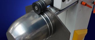
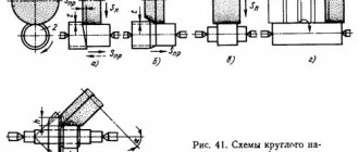
IB2222 Procedure for operating the machine when bending a cylindrical shell
- The sheet is inserted between the top and side rollers. In this case, the edge of the sheet should be aligned parallel to the generatrix of the front roll
- The rear side roller moves to its lowest position
- The front side roller moves to the uppermost position and the sheet is clamped
- The rear side roll moves upward and the leading edge of the sheet is hemmed
- Side rolls are installed in a symmetrical pattern (at the same level relative to the top)
- The sheet moves to the extreme forward position
- The second edge of the sheet is hemmed, similar to the first
- Side rolls are installed in a symmetrical pattern
- The sheet is bent into a cylinder. The bending radius depends on the position of the side rolls relative to the top, which are controlled using indicators located on the right column of the machine
- The left support of the upper roll is folded back and the shell is removed
Attention
Because When bending the edges of the sheet is carried out according to an asymmetrical pattern, in this case greater radial forces arise than with a symmetrical pattern. For this reason, the machine can bend edges of smaller thickness (see Table 1).
When working, more attention is required to the correct adjustment and installation of the workpiece in the rolls, as well as monitoring the movement of the workpiece during the bending process. After each transition, you should check the parallelism of the edge of the sheet forming the roll.
The flat workpiece must be pre-corrected because the presence of curvature causes its distortion and displacement of the end edges of the shell.
The displacement of the edges is corrected by reverse skewing of the shell in the rolls. Editing is possible if the shell is not completely bent.
Design Features
Rollers (also called sheet bending machines) allow controlled plastic deformation of sheets made of metal. Operating on the rolling principle, such a device is equipped with several shafts, which, when a metal sheet or pipe passes between them, changes their configuration. Serial models of such sheet bending equipment and homemade rollers work on the same principle and, accordingly, have a similar design. Let's look at the main elements of the machine.
Design of manual three-roll rollers
Bed-base
This is a load-bearing element that ensures the stability of the rollers, as well as the correct relative position of all their components.
Two vertical support posts
In their bearing units, shafts are installed, of which there can be only two (two-roll machine), three (three-roll machine) or even four. In the design of most rollers equipped with three working bodies, the two lower rollers can change their position only in the horizontal plane, and the third, a thrust roller located on top, is also adjustable in height. In addition, the upper roller for removing the finished part is equipped with a quick tipping mechanism.
Mechanism for lifting the upper pressure shaft
Rolls
During the processing of a sheet blank, the rolls must rotate, for which any rolling machine is equipped with a drive mechanism, which can be chain or gear. The operation scheme of such rollers is such that only the lower rollers are driven into rotation, and the upper one, tightly pressed against the surface of the workpiece, rotates under the influence of friction forces.
Roll operation diagram
Rollers can be equipped with various types of drives. Thus, depending on this parameter, rolling devices of the following categories are distinguished.
Manual
These are the simplest rollers, which are most often made by hand. To drive such devices, chain and gear drives can be used, the parameters of which should be selected depending on the characteristics of the material being processed. Hand rollers, taking into account the fact that significant physical effort is required to operate them, are used primarily for processing small workpieces.
Electrically driven
In terms of their performance, such rollers belong to the average category. Electrically driven three-roll rollers, due to the sufficiently high power of the drive mechanism, make it possible to process workpieces of considerable size.
Electromechanical rollers are often a modification of a manual machine to which a motor and control panel have been added.
Hydraulically driven.
This is the most powerful of all rolling equipment on the market today. Due to the fact that the hydraulic drive with which such rollers are equipped allows their working bodies to act on the workpiece with great force, such a device can effectively process metal sheets of even very significant thickness.
Among industrial hydraulic rollers there are even such giants
The quality of processing performed on rollers is primarily influenced by the characteristics of the rollers. Since the rolls experience significant mechanical loads during operation, high-strength tool steel is used for their manufacture. In addition to the mechanical impact, when processing sheet blanks of considerable thickness, which are preheated to give them greater plasticity, the rollers also experience thermal impact. It should be noted that such an impact, which can be very significant, has a rather negative impact on the operational characteristics of the rolls.
The quality of processing performed on rollers can be improved by equipping them with CNC systems, the tasks of which include coordinating all operating modes of the machine (the relative position of the rollers, the amount of pressure exerted on the workpiece, etc.).
IB2222 Setting up a machine for bending conical shells
Setting up the IB2222 machine for bending conical shells
To bend conical shells, the upper roller is placed in an inclined position at an angle ε to the horizontal. Angle ε and the amount of movement of the left support of the upper roll Δh left. are obtained from the following relationships between the cone angle and the required bending radii (see Fig. 28).
The angle at the top of the conical shells (maximum) is for machines:
- IB2213 - 30°
- IB2220, IB2216, IB2222 - 20°
- IB2219 — 15°
Install the upper roller in the position for bending conical shells in the following sequence:
- loosen the lower spline nuts on the tilt support screw
- Using the front link, set the upper roller to the desired position while simultaneously turning the screw into the glass by rotating the coupling manually. Control of movement along the ruler on the stand
- tighten the lower spline nuts with slight force. Open the folding support and tighten the top nuts. Tighten the lower nuts, close the support
- Use nuts to secure the upper roller console rod, while adjusting the free tilting of the left support
- adjust the position of the limit switch using the grooves in the limit switch bracket and the stop bar in the tilt support drive
- Place a device for bending conical shells on the neck of the upper roll with the folding support removed. When putting on the folding support, the shank of the device stop must enter the device by rotating around the landing neck - the roll.
- Return the roller to the horizontal position in the reverse order. When bending conical shells, the sheet is installed in such a way that the concave edge of the smaller diameter of the truncated cone workpiece is adjacent to the stop of the device for bending conical shells.
- D1 = 270 (top roll diameter)
- D2 = 260 (diameter of side rolls)
- * d1 = 324 (setup diameter for pipe bending for the upper roll)
- * d2 = 314 (diameter of setting for bending pipes for side rolls)
- * d3 = 360 (diameter of setup for bending long products)
- R = 420
Where *dimensions for reference:
Maximum dimensions of long products and Rmin minimum bending radius:
- pipe bending tools . Maximum pipe diameter - Ø32; 45, Rmin = 400 mm
- Setting up a tool for bending a double angle with the flange facing outwards. Maximum dimensions of the corner - 50x50x5, Rmin = 450 mm
- Setting up a tool for bending a channel with the flange facing outwards. Maximum channel size - No. 12, Rmin = 400 mm
- square bending tool . Maximum square dimensions - 50x50, Rmin = 300 mm
- Setting up a tool for bending strips on edge. Maximum strip dimensions - 36x60, Rmin = 400 mm
How to develop technical specifications for the development of a rolling machine with your own hands
The simplest diagram of a three-roll manual machine includes:
- Frame base.
- Two side posts with holes for bearing units.
- Three longitudinal shafts, one of which – the upper one – is placed at an angle of 60° relative to the other two.
- A set of work rolls, the number of which depends on the maximum value of the outer diameter of the workpiece being rolled.
- A handle for rotating the lower drive rollers.
- A gear or chain transmission that will ensure synchronous rotation of the drive rolls in one direction.
- A pressure unit with compression springs, which will provide the ability to press the non-drive roll against the workpiece. It is easier to do it on the left or right, since the thin sheet comes out of the gap quite easily when changing its original value on only one side.
- A device for rotating one of the stands of a rolling machine in order to replace work rolls.
First of all, it is necessary to clearly limit the technical capabilities of the designed rolling equipment. A manually driven rolling machine is capable of bending sheet metal with a thickness of no more than 1 - 1.5 mm, with a workpiece width of up to 600 mm. With the low energy intensity of the bending process itself, friction losses in gears and bearings turn out to be very significant, which will force the operator to increase the muscular force applied to rotate the work rolls. Meanwhile, the visible unevenness of their rotation will cause unwanted distortions in the shape of the profiled product.
Of the two options - asymmetrical or symmetrical placement of drive rolls - preference should be given to the second option, since in this case it is much easier to make rollers with your own hands.
Technical characteristics of three-roll plate bending machine IB2222
| Parameter name | IB2220 | IB2222 | IB2222V |
| Main parameters of the machine | |||
| Maximum thickness of bent sheet at bt = 250 MPa (25 kgf/mm²), mm | 10 | 16 | 16 |
| Maximum width of bent sheet, mm | 2000 | 2000 | 2000 |
| Maximum angle at the top of conical shells, degrees | 20 | 20 | |
| Bending speed, m/min | 9.3 | 7,7 | 8,5 |
| Minimum bending radius, mm | 180 | 240 | 240 |
| Upper roll diameter, mm | 215 | 270 | 270 |
| Diameter of side rolls, mm | 195 | 260 | 260 |
| Electrical equipment and machine drive | |||
| Number of electric motors, kW | 4 | 4 | 4 |
| Electric motor (main) drive of rotation of side rolls, kW | 8,5 | 12,0 | 12,0 |
| Electric motor of the tilting mechanism of the folding support of the upper roll, kW | 1,1 | 1,1 | 1,1 |
| Electric motors for adjusting the height of the side rolls, kW | 3,0 | 5,5 | 5,5 |
| *Electric motor drive of the product removal mechanism (pusher) (M5), kW | 1,5 | 1,5 | 1,5 |
| *Electric motor for driving the shell support (M6), kW | 0,75 | 0,75 | 0,75 |
| Total power of electric motors, kW | |||
| Dimensions and weight of the machine | |||
| Dimensions (length x width x height), mm | 3940 x 1250 x 1310 | 4040 x 1490 x 1745 | 4040 x 1590 x 2096 |
| Weight, kg | 5850 | 11495 | 8890 |
- Banquetov A.N., Bocharov Yu.A., Dobrinsky N.S. and others. Press-forging equipment, 1970
- Bocharov Yu.A., Prokofiev V, N. Hydraulic drive of forging and pressing machines, 1969
- Belov A.F., Rozanov B.V., Linz V.P. Volumetric stamping on hydraulic presses, 1971
- Zhivov L.I. Forging and stamping equipment, 2006
- Kuzmintsev V.N. Forging with hammers and presses, 1979
- Rozanov B.V. Hydraulic presses, 1959
- Titov Yu.A. Equipment for forging and pressing shops, 2001
- Shcheglov V.F. Forging and pressing machines, 1989
- Berlet Development of forging drawings, 2001
- Rudman L.I. Sheet Forming Equipment Handbook, 1989
- Romanovsky V.P. Handbook of Cold Forging, 1965
- Okhrimenko Ya.M. Technology of forging and stamping production, 1966
- Kuzmintsev V.N. Forging with hammers and presses, 1979
- Meshcherin V.T. Sheet stamping. Atlas of circuits, 1975
Bibliography:
Related Links. Additional Information
- Manufacturers of forging and pressing equipment in Russia
- Classification and designation of hydraulic and crank presses
- Mechanical presses
- Hydraulic presses
- Automatic forging and pressing machines
- Bending and straightening machines
- Guillotine shears, press shears
- Hammers
- Repair of hydraulic systems of metal-cutting machines
- Designations of hydraulic circuits of metal-cutting machines
- Repair of gear hydraulic pumps
Home About the company News Articles Price list Contacts Reference information Interesting video KPO woodworking machines Manufacturers