The discovery of the principle of electromagnetic induction by the great scientist Faraday back in 1831 allowed us to take a fresh look at many laws of electrical engineering. It was based on the interaction of electromagnetic fields that 45 years after this, the great Russian scientist P. N. Yablochkov received a patent for the invention of a transformer. The classic definition is as follows: a transformer is an electrical device that converts the current of the primary winding of one voltage into the current of the secondary winding with a different voltage.
The induction effect is formed when the electromagnetic field changes, so for the transformer to operate, an alternating current voltage must be present. Transformation (transmission) is carried out by converting the electrical energy of the primary winding into a magnetic field, and then, in the secondary winding, the reverse conversion of the magnetic field into electrical energy occurs. If the number of turns of the secondary winding exceeds the number of turns of the primary winding, the device will be called a step-up transformer. When connecting the windings in reverse order, a step-down device is obtained.
Design and principle of operation
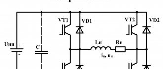
Structurally, the boosting voltage transformation device consists of a core and two windings . The core is assembled from electrical sheet steel plates. The primary and secondary windings are wound on it, made of copper wire of various diameters. The thickness of the transformer winding wire directly depends on its output power.
The core of the device can be rod or armor. When using the product in low-frequency voltage networks, rod magnet wires are most often used, which can be shaped like:
- U-shaped.
- W-shaped.
- Toroidal.
Cores are made from transformer special iron, on the quality characteristics of which many general parameters of the device depend. A core is made of thin iron plates, which are insulated from each other with varnish or a layer of oxide, to reduce losses due to eddy currents. Ready-made halves, which are made from solid iron strips, can also be used.
Advantages and disadvantages of cores
- Stacked ones are more often used for constructing magnetic cores with an arbitrary cross-section, limited only by the width of the plates. Voltage transformation devices with a square cross-section have the best parameters. The disadvantage of this type of core is the need to tightly tighten the plates, the low fill factor of the coil space, as well as increased dissipation of the magnetic field of the device.
- Twisted cores are much easier to assemble than type-type ones. The entire W-type core consists of four parts, while the U-shaped type has only two parts in its design. The technical characteristics of such a transformer are much better than those of a type-setting transformer. The disadvantages include the need for a minimum gap between parts. With physical impact, the plates of the parts can peel off, and in the future it is very difficult to achieve a tight fit.
- Toroidal cores have the shape of a ring, which is made of transformer iron tape. Such cores have the best technical characteristics and almost complete elimination of magnetic field dissipation. The disadvantage is the difficulty of winding, especially wires with a large cross-section.
In W-type transformers, all windings are usually made on the central rod. In a U-shaped device, the secondary winding can be wound on one rod, and the primary winding on another. Especially often, there are design solutions when windings divided in half are wound on both rods, and then connected to each other in series. At the same time, the wire consumption for the transformer is significantly reduced and the technical characteristics of the device are improved.
Specifications
The main characteristics when operating a transformer are:
- Input voltage.
- Output voltage value.
- Device power.
- Open circuit current and voltage.
The ratio of voltages at the input and output of a device is called the transformation ratio. This ratio depends only on the number of turns in the windings and remains unchanged in any operating mode of the device.
The power of the transformer directly depends on the diameter of the wires and the type of core, which on the side of the primary winding is equal to the sum of the powers of the secondary windings, excluding losses.
The voltage obtained at the output winding of the device, without connecting a load, is called open-circuit voltage. The difference between this indicator and the load voltage indicates the amount of loss due to the different resistance of the winding wires.
The value of the no-load current completely depends on the quality indicators of the transformer core . In an ideal case, the current of the primary winding creates a magnetic field of variable value in the core of the device, the electromotive force of which is equal in magnitude to the no-load current and opposite in direction. But in reality, the magnitude of the electromotive force is always less than the input voltage, due to possible losses in the core.
That is why, in order to reduce the value of the no-load current, high-quality material is required in the manufacture of the core and a minimum gap between its plates. Toroidal cores are more suitable for such conditions.
Other types
In accordance with the performance characteristics, the presented equipment differs in several ways. Depending on the number of circuits, there are single-phase (domestic) and three-phase (industrial) designs.
Various substances are used as a cooling system. There are oil and dry varieties. In the first case, the equipment costs less. Oil is a flammable substance. When used, high-quality protection against accidents is provided. Dry units are filled with a non-flammable substance. They are more expensive, but the requirements for their installation are fair.
Coolant circulation in the system can be forced or natural. There are designs that combine these methods. The variety of types allows everyone to choose the optimal type of device.
Device types
Depending on the power, design and scope of their application, there are the following types of transformers:
- The autotransformer is structurally designed as one winding with two end terminals, and at intermediate points of the device there are several terminals in which the primary and secondary coils are located.
- The current transformer includes a primary and secondary winding, a core made of magnetic material, as well as optical sensors and special resistors that allow for faster voltage regulation methods.
- A power transformer is a device that transmits current, using the induction of an electromagnetic field, between two circuits. Such transformers can be step-up or step-down, dry or oil-based.
- Anti-resonance transformers can be either single-phase or three-phase. The operating principle of such a device is not much different from power type transformers. Structurally, it is a cast-type device with good thermal protection and a semi-closed structure. Anti-resonance transformers are used when transmitting signals over long distances and under heavy load conditions. Ideal for working in any climatic conditions.
- Grounded transformers (pre-load) . A special feature of this type is the arrangement of the windings in the shape of a star or zigzag. Grounded devices are often used to connect an electric energy meter.
- Peak - transformers are used in radio communication devices and computer production technologies, on the principle of separating direct and alternating current. The design of such a transformer is simplified: a winding with a certain number of turns is located around a core made of ferromagnetic material.
- A home isolation transformer is used when transferring AC power to another device or equipment, thereby blocking the ability of the power source. In domestic conditions, such devices provide voltage regulation and galvanic isolation. Most often used to suppress electrical noise in sensitive devices and protect against the harmful effects of electric current.
How to reduce the output voltage of a transformer?
- Because most transformers are always a center tap for dual power supplies. ...
- Primary transformer 230/110 VAC to secondary transformer 9-0-9 V, 1 A. ...
- Usually we can easily apply it as 18V 1A output without using CT terminal.
- Moreover, we can use it as 9V 2A since both coils are connected in parallel.
Useful tips Connection diagrams Principles of operation of devices Main concepts Meters from Energomer Precautions Incandescent lamps Video instructions for the master Testing with a multimeter
Maintenance and repair
It is advisable for a person who does not know the operating principle of electrical devices not to carry out repair work on this equipment, due to the possibility of electric shock. When repairing and servicing transformer devices, the only thing that can be fixed without unacceptable consequences is rewinding the transformer.
Before starting any repair work, it is necessary to check the transformer:
- The first step is to assess the condition of the device through a visual inspection, since sometimes darkened and swollen areas directly indicate a malfunction of the transformer winding.
- Determine if the device is connected correctly. The electrical circuit generating the magnetic field must be connected to the primary winding of the device. But the second circuit, which consumes the energy of the transformer, must be included in the output voltage winding.
- Phase filtering of the output signal is determined for both diodes and capacitors on the secondary winding of the device.
- The next step is to prepare the device for control measurement of parameters, i.e. remove the protective panels and covers to gain free access to the circuit elements. Using the tester, you need to subsequently measure the voltage of the transformer.
- To carry out measurements, you need to supply power to the device circuit. The parameters of the primary winding are measured with a tester in AC mode. If the resulting value is less than 80% of the expected value, then the fault may be in the transformer itself or in the circuitry of the entire device.
- The output winding is checked using a tester. At the same time, we check the winding both for the possibility of short-circuited turns and for a break in the coil winding wire, according to the principle of measuring resistance (if the resistance is low, then there is a possibility of short-circuited turns, and in the case when the winding resistance is high, a break).
After rewinding the step-up voltage transformer, in the event of a winding malfunction, you need to assemble it in the reverse order, paying special attention to the tightest fit of the core plates.
Making or repairing a device yourself is a very complex and time-consuming process. To perform such work, you will need the necessary materials, as well as the ability to make some special calculations. In particular, you will need to accurately calculate the number of turns in the transformer winding, the diameter of the wires for the winding, as well as the cross-section and type of the device core.
Therefore, it is better to contact a qualified person who is familiar with the basic concepts and properties of electrical engineering and calculations using the necessary formulas to carry out these operations.
Operation
To understand what voltage-increasing transformers are, you need to understand the principle of operation. The equipment is manufactured for power plants whose design schemes belong to the pass-through category.
A step-up transformer at power plants is used to provide populated areas and other objects with current with certain technical indicators. Without a converter, the high voltage gradually decreases along its path. The end consumer would receive insufficient electricity. At the final power plant in the circuit, thanks to this installation, electricity of the appropriate value is received. The consumer receives a network voltage of up to 220 V. Industrial networks are provided with up to 380 V.
A diagram showing the operation of a transformer in a line includes several elements. The generator at the power plant produces 12 kV electricity. It is supplied through wires to step-up substations. A transformer apparatus is installed here, designed to increase the indicator in the line to 400 kV.
From the substation, electricity enters the high-voltage line. Next, the energy enters the step-down substation. Here it drops to 12 kV.
Transformers with a reverse operating principle direct the current to the low-voltage transmission line. At the end, another step-down unit is installed. From it, electricity with an indicator of 220 V is supplied to houses, apartments, etc.