FEDERAL STATE BUDGET EDUCATIONAL INSTITUTION
HIGHER PROFESSIONAL EDUCATION
"IZHEVSK STATE AGRICULTURAL ACADEMY"
DEPARTMENT
"ELECTRICAL TECHNOLOGY OF AGRICULTURAL PRODUCTION"
Methodical manual for calculation and graphic work on hydrogas dynamics
Specialty 140106 – Energy supply for enterprises
Compiled by: P.L. Lekomtsev
Izhevsk 2009
Evolutionary history of the nozzle
When did a person first use a nozzle?
Already in the 1st century, Heron of Alexandria proposed a jet nozzle for his “aeolipil”. In it, two multidirectional steam nozzles rotated a hollow metal ball with reactive force. 1,200 years later, China made gunpowder rockets—for fireworks and for combat—having mastered jet propulsion in practice. In the Middle Ages, military missiles began to fly in Europe. In the Russian army of the 19th century, missile weapons grew to regular foot and mounted missile teams that fired missiles from special launchers; mass missiles in the navy, large missile factories such as the largest plant in Europe in Nikolaev. The first launch of combat missiles from an underwater position of a missile submarine occurred during Pushkin’s lifetime, on August 29, 1834, on the Neva, 40 miles above St. Petersburg. Nozzle is a device for accelerating the flow of liquid or gas. Why overclock it? In some cases, you need the fast flow itself, which is used further. In others, it is not the flow that is needed, but the force that arises when it is released - reactive. Such a power nozzle is called a jet nozzle. It was the jet nozzles that were practically mastered first with the advent of the first rockets.
Simultaneously with the widespread use of rockets, steam technology at the end of the 19th century reached steam turbines that rotated ship propellers. A high-speed jet was required to flow around the turbine blades, and the faster the speed of the steam jet, the greater the force it created on the turbine blades, increasing its power. The nozzle here was required not for reactive force (which, of course, also arose, but as a side, unused effect), but to create a high-speed flow. Through it, the energy thrown by the nozzle in the form of a mass of steam will fall on the blades and do work on them, spinning them with force. The total force of the blades is transmitted to the propeller.
While working on a high-speed steam turbine nozzle, Swedish engineer Carl Gustav Patrick de Laval proposed a fundamentally new type of nozzle in 1890. It was able to accelerate the flow to supersonic speeds, which had never been possible before. Thus the supersonic Rubicon was crossed, immediately doubling the exhaust velocity.
see also
- Plugged flow - when the gas speed reaches the speed of sound in the gas passing through the restriction
- De Laval nozzle - a convergent-divergent nozzle designed to create supersonic speeds
- Dual thrust rocket engines
- Giovanni Battista Venturi
- Jet engine - jet engines (including rocket engines)
- Multistage rocket
- NK-33 - Russian rocket engine
- Pulse jet engine
- Pulse rocket engine
- Skylon Reaction Engines - a single-stage orbital spaceplane with a hybrid air-oxygen engine (SABRE Reaction Engines)
- Rocket - rocket cars
- Rocket engines - used to propel rocket technology
- SERN, Single expansion ramp nozzle - non-axisymmetric aerodynamic projectile
- Impact diamonds are visible streaks in rocket engine exhaust.
- Solid fuel rocket
- Spaceship movement
- Specific impulse is a measure of exhaust velocity.
- Staged combustion cycle (rocket) - type of rocket engine
- Venturi effect
Supersonic Rubicon
Both at the nozzles of Heron’s aeolipile and at the tip of the fire cannon (and this is a nozzle for accelerating the stream of water), the flow channel narrows. In such a channel, the flow of the working fluid - steam, gas or liquid - accelerates. Why? The flow rate (the amount of working fluid passing through a section per second) is the same anywhere in the channel - as much as flows in through the initial section, so much must exit through the final section. After all, the substance flowing through the channel does not decrease or increase; there are no holes in the walls that supply or discharge it. And the law of conservation of mass makes the flow of matter through any place in the nozzle the same.
Both the liquid and the subsonic gas flow practically do not change their volume, therefore they are approximately considered as incompressible, when the speed of sound is still far away. A constant consumption of their mass means a constant consumption of their volume. The flow has to hurry to drive the same volume through the narrowed place. The gas is forced to accelerate.
Supersonic jets from the engines of the Proton-M launch vehicle, launch on July 31, 2022 from the Baikonur Cosmodrome. Photo: Roscosmos.
It is caused by a pressure difference to flow - the flow flows towards low pressure, pushed from behind by high pressure. In a narrowing channel, the pressure and temperature of the flow continuously fall, but its speed increases. The potential energy of pressure and temperature of the gas is pumped into the energy of movement, into its acceleration. The higher the pressure difference between the beginning and the exit of the nozzle, the greater the acceleration and exhaust velocity. To increase it, the pressure in front of the nozzle is increased. The same is true for temperature differences, and they try to heat the gas more by burning fuel components.
But the exhaust velocity turned out to have its own fundamental limit. This is an outflow at the speed of sound. It is not overcome by any increase in pressure at the nozzle inlet. No matter how much it is raised, two, four or ten times, within the converging nozzle the flow will not exceed the speed of sound.
Let us remember what subsonic and supersonic motion is. The speed of sound (weak wave compactions in a gas) depends on many factors - the composition of the gas, its density and pressure. But most of all it depends on temperature. Under specific conditions, the speed of sound takes on a specific local value. Compares the flow speed with the local speed of sound, the Mach number, dividing the flow speed by the speed of sound. Its value is denoted M and shows how many times the flow speed is greater or less than the speed of sound. When M is less than one, the flow is slower than sound - subsonic. When M=1 the flow flows exactly at the speed of sound. At M > 1 the flow is supersonic.
It is possible to overcome the sound boundary only by using a special principle. It is called the principle of reversal of influence.
In gas dynamics there is the concept of influence. This influences the gas flow, changing its parameters, including speed. The narrowing of the channel is a geometric effect, a change in the flow geometry. And there is a principle of reversal of influence. According to him, the same impact can change the flow speed only up to the speed of sound. Moreover, this is true for both acceleration and braking (if the flow is supersonic). The maximum achieved by the same impact will always be the speed of sound, M=1. Becoming an insurmountable sound barrier for this impact. Beyond this limit, exposure to any power will not be able to do anything.
Launch of the Soyuz-2.1a launch vehicle with the Progress MS-14 cargo ship. April 25, 2022, Baikonur. It can be seen how excess carbon burns out with a yellow flame outside the flow at the periphery of the jet stream in the oxygen of the surrounding air. It is this external afterburning that makes the jet so bright; in an oxygen-free atmosphere it would not glow and would look like an inconspicuous gray ribbon. Where does the excess carbon come from on the periphery of the nozzle flow, and what else is visible on these jets - here. Photo: Roscosmos.
To step beyond M=1 and continue accelerating or decelerating the flow, you need to change the effect to the opposite. In case of geometric influence (narrowing of the channel), its sign must be changed. For overclocking, this is a change from contraction to expansion. Where to change, when? After the flow reaches the speed of sound. In the expanding part, the flow will become supersonic and will accelerate further. Why?
Having become supersonic, the flow acquires critically different properties. Subsonic incompressibility is replaced by greater compressibility and expandability. The expansion of the gas is so great that it overtakes the geometric expansion of the channel. The swelling gas is forced to flow faster and faster even through increasing cross-sections of the channel. Therefore, the flow velocity in the supersonic expansion of the nozzle increases, and the gas density decreases. Laval proposed this nozzle shape and obtained a supersonic flow at the exit. A nozzle with a narrowing-expansion geometry was called a Laval nozzle.
Sandblasting nozzle: rules for choosing and making it yourself
The nozzle, which is used to equip a sandblasting machine, is the most important design element of such a device.
Only a correctly selected nozzle will allow you to most effectively use the sandblaster for its intended purpose: to clean various surfaces from dirt, old coatings, traces of corrosion, degrease them and prepare them for further processing.
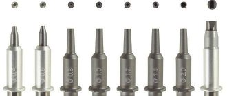
For each application, you can select a nozzle of a certain diameter, depending on the fraction of sand used
The tasks that a sandblasting nozzle solves are to compress and accelerate to the required speed a mixture consisting of air and abrasive material, as well as to form a working spot and saturate it with abrasive acting on the surface of the workpiece.
Depending on the size of the surface to be sandblasted, different types of holes can be made in the nozzles.
Thus, for processing narrow surfaces, nozzles with the same diameter along the entire length are used, and for cleaning large surfaces, products are used, the holes in which have larger diameters at the inlet and outlet (Venturi type, developed in the middle of the last century).
The essence of sandblasting
Sandblasting involves exposing various surfaces to an abrasive material. Sand, shot, silicon carbide, small glass beads, etc. are used as the latter.
Sandblasting is a mechanical action on the surface of small solid particles
Before processing begins, the abrasive is placed in a sealed hopper. Air coming from a separate compressor is supplied through the main hose of the device under high pressure.
Passing by the opening of the intake hose, the air flow creates a vacuum in it, which facilitates the suction of abrasive into the main hose.
The air, already mixed with abrasive, is supplied to the gun, the main element of which is a sandblasting nozzle, through which the abrasive mixture is supplied to the surface being treated.
Layout of the sandblasting area
As mentioned above, various types of abrasives can be used to perform sandblasting. The choice here depends on the type of surface that needs to be cleaned.
Thus, treatment using sand is effective in cases where it is necessary to remove a layer of old paint from a concrete surface, clean brick walls from cement residues, and prepare metal parts for further painting.
Abrasives such as plastic or wheat starch are successfully used in the shipbuilding, automotive and aircraft manufacturing industries, with their help they effectively remove old coatings from composite materials.
Design features of a nozzle for a sandblasting machine
The main parameters of the nozzle installed on the sandblasting machine are:
- diameter and type of hole;
- length;
- manufacturing material.
Abrasive blasting nozzles of various configurations
The diameter of the hole in the nozzle, which is fixed on the sandblasting machine using a special nozzle holder, is selected depending on the performance the device should have.
The performance of any sandblasting machine - both serial and home-made - depends on the power of the jet or the volume of air that the nozzle is able to pass per unit time.
The power of the jet generated by the nozzle is directly proportional to the volume of air that passes through it per unit time. Accordingly, in order to increase the power of the sandblasting machine, it is necessary to make a hole of a larger diameter in its nozzle.
For example, you can estimate the power of nozzles whose holes have different diameters.
If a nozzle whose diameter corresponds to 6 mm (1/4 inch) has a power equal to 100%, then products with holes of larger diameters will differ in the following value of this parameter:
- 8 mm (5/16 inch) – 157%;
- 9.5 mm (3/8 inch) – 220%;
- 11 mm (7/16 inch) – 320%;
- 12.5 mm (1/2 inch) – 400%.
To better understand the power of a nozzle with a particular internal hole diameter, you can take into account that products with a diameter of 6 mm (1/4 inch) are capable of providing an average jet power of 30 m3/hour.
The table allows you to roughly estimate the effect of nozzle diameter and air pressure on productivity and abrasive consumption
If you are not going to make a nozzle for a sandblasting machine with your own hands, then you should keep in mind that mass-produced products have standard hole diameters of 6, 8, 10 and 12 mm.
The choice of a nozzle parameter such as its length is influenced by the degree of contamination of the surface being cleaned. For sandblasting surfaces that have minor contamination, shorter nozzles (7–8 cm) are selected.
If it is necessary to treat a surface on which there are complex contaminants, the length of the nozzle must be significant (up to 23 cm).
Shorter nozzles, installed in a standard nozzle holder, are also used in cases where hard-to-reach areas need to be treated.
Nozzles, the diameter of which does not change along their entire length, make it possible to ensure an exit speed of the abrasive material of 320 km/h, while the pressure of the mixture of air and abrasive coming from such a nozzle is 6 atm.
Nozzles with a Venturi channel form a jet of an abrasive mixture, the speed of which can reach up to 720 km/h. It is clear that nozzles with internal holes of this type increase the efficiency of sandblasting.
It is obvious that the flow area of the VENTURI type nozzle is significantly larger than that of a conventional straight line
The use of nozzles with Venturi-type internal holes allows enterprises and specialized companies not only to increase their productivity, but also to significantly improve the quality of the processing performed. What is important is that the use of products with such channels does not require the purchase of special abrasives and does not lead to an increase in compressed air consumption.
If nozzles with holes of the usual type for sandblasting machines can be made with your own hands (although this is difficult), then it is almost impossible to make products with a Venturi channel at home without special equipment.
Design of a sandblasting nozzle with a Venturi channel: d - internal diameter; D—inlet diameter; T - connecting thread; L—nozzle length
To make nozzles, including with your own hands, various materials can be used, the choice of which determines the durability of the product. Thus, depending on the material used, nozzles for sandblasting machines have the following durability:
- ceramic products that are made at home from ordinary spark plugs - 1–2 hours;
- cast iron nozzles – 6–8 hours;
- products for the production of which tungsten carbide was used – 300 hours;
- nozzles made of boron carbide - 750–1000 hours.
If steel shot, rather than sand, is used as an abrasive material in a sandblasting machine, then the durability of any type of nozzle increases by 2–2.5 times.
How to choose the right sandblasting nozzle
When choosing a nozzle for your sandblaster, consider the fact that the most inexpensive products are also the most short-lived. Such nozzles will ultimately cost you more than quality products, especially if you have a large amount of work to do.
Sandblasting Wear Resistant Tungsten Carbide Nozzles
Nozzles made of cast iron and ceramics are suitable for domestic purposes. Many home craftsmen even make ceramic nozzles on their own using used spark plugs. In order to make a nozzle from such a candle, it is enough to remove the metal electrode from its ceramic shell.
When using cast iron and ceramic nozzles for a sandblasting machine, it should be borne in mind that due to their accelerated wear, they increase the consumption of both air and abrasive, so they are not recommended for use when performing large-scale work.
Expensive boron carbide and tungsten carbide nozzles not only offer superior durability, but they can also be used with virtually any abrasive except carborundum and aluminum oxide.
This, in fact, explains the rather high cost of such nozzles for a sandblasting machine, which can last a very long time without losing their characteristics or increasing the consumption of abrasive material and air. The use of such products is advisable in all situations where a large amount of work is required to clean various surfaces.
Ways to achieve supersonic
Note that it is not only the changing geometry of the Laval nozzle that can accelerate the flow to supersonic. Supersonic nozzles with unchanged channel geometry are possible, just with a straight pipe. There are three types: mass, thermal and mechanical. And they all work on the principle of reversal of influence. The mass nozzle has perforated walls. In the subsonic part of the pipe, gas is pumped inside through perforations in the walls. To pass an increasing amount of gas through the pipe, the gas accelerates, reaching the speed of sound. And after the speed of sound, the effect changes to the opposite - gas is pumped out of the pipe through holes in the walls. What causes expansion (there is room after pumping) and acceleration of the gas remaining in the pipe. To accelerate the flow, the gas mass flow rate changes - that’s why the nozzle is called a mass nozzle.
The other two types are purely theoretical. Thermal nozzle - when moving through an unchanged pipe, the gas heats up, reaching the speed of sound. And after it the gas is cooled with supersonic acceleration. A mechanical nozzle supplies energy to the gas by mechanical force, and at the speed of sound it also mechanically removes energy to accelerate the supersonic flow.
The Laval nozzle is a special case of the principle of impact reversal, its geometric avatar. Two opposing funnels with a common bottleneck. This type of nozzle is widely used in practical matters. Because reaching the speed of sound radically changes the behavior of the flow, the speed of sound is called the critical speed. And the cross section of the nozzle (always the smallest), in which the speed of sound is achieved, was called the critical cross section of the nozzle.
In the tapering subsonic part of the nozzle, the gas density changes insignificantly, and it expands slightly. But its pressure and temperature decrease significantly - the speed increases mainly due to them. These parameters drop most steeply in the critical part of the nozzle, in the sound speed zone. The change in impact maintains these flow changes further, in the supersonic part, adding gas expansion. Therefore, the flow speed continuously increases in both parts of the nozzle - both subsonic and supersonic.
A subsonic gas flow behaves like a river flow, an incompressible liquid that maintains volume. Absolutely? No, as the speed increases, the air flowing around the body gradually compresses, but only slightly; the compression ratio does not exceed a few tens of percent. This does not fundamentally change the flow pattern, leaving it within the framework of hydrodynamics, or “hydrodynamics for air” - aerodynamics. The picture remains this way until the sound rubicon.
Behind the speed of sound lies gas dynamics. Here the compressibility of the gas is fully manifested: it compresses and expands many times, several times and tens of times. This radically changes the flowing volumes and creates critical changes in the picture.
A supersonic flow behaves in the opposite way to a subsonic flow - it slows down when it contracts, and accelerates when it expands. If it slows down, it does so abruptly and instantly, always with volume compression and heating, forming sharp compaction boundaries within itself. And finally, a supersonic flow can flow towards high pressure - for example, into this very seal.
A different nature of the driving force allows a supersonic flow to flow against the pressure difference. It is not the gas pressure that becomes dominant, as in a subsonic flow, but the inertial force of motion. The behavior of a subsonic flow is controlled by a thermal entity - the potential energy of gas pressure, and the supersonic properties of the flow are created by another form of energy - the kinetic energy of motion.
Do-it-yourself Laval nozzle - Metalist's Handbook
To produce affordable building materials, various types of equipment are used, including a foam generator for foam concrete.
Despite the ease of manufacture and low cost, the technical requirements for foam concrete blocks are strict.
To achieve high quality in the production of this building material, it is necessary to strictly comply with all technological standards.
Purpose of the foam generator
Currently, foam concrete is in demand in individual construction as an affordable and high-quality material. This is due to its high performance characteristics.
Low-rise residential buildings, garages, country houses and various outbuildings are erected from foam concrete.
Foam blocks do not burn and are not subject to shrinkage; they are sufficiently resistant to any atmospheric influences.
In winter, buildings made of foam concrete retain heat well; in summer, such rooms are not hot. You can produce foam concrete yourself using a homemade foam generator.
:
The practice of recent years shows that more and more people are striving to build a house or garage on their own. This approach has become widespread due to technical capabilities.
Equipment for the production of foam concrete can be purchased at an affordable price or made independently.
One of the main elements of the installation is a foam generator. This device is used to ensure that the concrete block is saturated with foam, thereby giving the block its characteristics.
Today on the construction equipment market you can find and buy a foam generator suitable for power.
However, you can make a foam generator for foam concrete with your own hands without significant financial costs, which will reduce construction costs.
The quality of the foam that is formed in homemade foam generators is exactly the same as in factory ones.
Once you become familiar with the operating principle of such a unit, you can draw your own drawings and begin manufacturing.
The foam generator consists of the following elements:
- shut-off and control equipment;
- chamber for forming the mixture;
- nozzle.
The specific design of the foam generator may undergo changes, but the principle of operation remains the same.
Operating principle
The main function of the foam generator is to ensure the supply of foam to the sand-cement mortar prepared in advance.
To produce foam concrete, an ordinary concrete mixer is used. Concrete is mixed in it for pouring foundations and walls or mortar for brickwork.
When, during the process of mixing the solution, a certain amount of foam gets into it, ordinary concrete turns into foam concrete.
All specialists are aware of the advantages and disadvantages of foam concrete. Today, this building material can be prepared directly on the site where a house, garage or other object is being built.
Foam Generator Structure
When starting to make a foam generator with your own hands, you need to optimize all the drawings and descriptions that catch your eye.
The fact is that many specialists, having become familiar with the operating principle of a foam generator, immediately apply the acquired knowledge, turning it into reality.
Schemes and drawings:
A clear demonstration of the operation of a foam generator can be seen at any car wash.
The foam, when mixed, fills a certain volume of the concrete block and thereby reduces its original density.
The simplest foam generator can be assembled from the following elements:
- foam solution supply pipe;
- compressed air supply pipe;
- mixing chamber;
- foam cartridge.
Factory-made foam concentrate is always available on the shelves in building materials stores.
If this is not possible, then the emulsion can be prepared by mixing gum rosin, caustic soda and bone wood glue. The cooking process is not complicated, but requires care.
After the homemade foaming agent is ready, you need to check its quality. The foam must have sufficient density and durability.
Assembly and connection
The main elements of a foam generator for the production of foam concrete are a mixing chamber and a foam cartridge. In this context, it is important to emphasize that behind these terms lie ordinary elements that are well known to masters.
The mixing chamber is an ordinary pipe. The diameter of the pipe is selected depending on the power of the future generator. Two pipes are welded to the pipe.
:
The first is at the end, intended for air supply, the second is in the middle of the pipe at an angle of 90 degrees. A foaming agent solution is supplied through it. A shut-off valve must be installed on each branch pipe.
Foam generators for factory-made foam concrete are equipped with two valves - a shut-off valve and an adjustment valve.
The practice of recent years shows that for small production volumes, when it is necessary to produce foam blocks for the construction of a garage or country house, one shut-off valve is sufficient.
A pipe is welded to the second end of the mixing chamber, which serves as a foam cartridge. If possible, the inner surface of the pipe is treated in the shape of a funnel.
This is done to reduce the flow rate of the foaming agent and air mixture to ensure foam formation.
Some nuances
When the mixing chamber and foam cartridge are connected, an element called a Laval nozzle or another device, a nozzle, is fixed between them.
These elements are designed to increase the flow rate of the mixture during the transition from the chamber to the foam cartridge. It is in the foam cartridge that the final formation of foam occurs.
To make the process more efficient, the flow of the foaming agent is “broken” against a special filter.
In homemade foam generators, kitchen metal mesh, which is sold in every hardware store, is used as such a filter.
Building a foam generator with your own hands to produce foam concrete is not a difficult task. The main thing here is to understand the principle of operation of the generator.
:
A technically more difficult task is to correctly connect the foam generator to the main equipment.
Currently, the designs of concrete mixers that are used for the production of blocks can be found in a variety of ways.
Before assembling the foam generator, it is necessary to determine all the installation elements that are used when connecting hoses and pipes.
Sandblasting nozzle: rules for choosing and making it yourself
The nozzle, which is used to equip a sandblasting machine, is the most important design element of such a device.
Only a correctly selected nozzle will allow you to most effectively use the sandblaster for its intended purpose: to clean various surfaces from dirt, old coatings, traces of corrosion, degrease them and prepare them for further processing.
For each application, you can select a nozzle of a certain diameter, depending on the fraction of sand used
The tasks that a sandblasting nozzle solves are to compress and accelerate to the required speed a mixture consisting of air and abrasive material, as well as to form a working spot and saturate it with abrasive acting on the surface of the workpiece.
Depending on the size of the surface to be sandblasted, different types of holes can be made in the nozzles.
Thus, for processing narrow surfaces, nozzles with the same diameter along the entire length are used, and for cleaning large surfaces, products are used, the holes in which have larger diameters at the inlet and outlet (Venturi type, developed in the middle of the last century).
Wasp waist and overextension
Classic rocket engine nozzles are funnel-shaped constrictions and expansions with a narrow wasp waist between them. It is narrow due to the high density in the combustion chamber. The compressed gas can expand many times, still maintaining a noticeable effect on the nozzle walls and creating thrust. The main expansion begins when approaching the speed of sound and continues throughout the entire supersonic part of the nozzle. In which the ratio of the final area to the initial one, that is, the cut-off area of the nozzle and the critical section, was called the degree of expansion of the nozzle. How much can you expand (and therefore accelerate) the gas inside the nozzle? In space, the rarefaction of the flow at the nozzle exit is brought to a practical benefit - until the addition of thrust at the extension of the nozzle justifies the increase in its mass. Unused remaining pressure is released into the void of space.
When launching from the surface of the Earth, the atmosphere presses into the nozzle, preventing the outflow. The jet flies out of the nozzle of a more expanded atmosphere - the density and pressure of the jet is lower than atmospheric. Such a jet is called overexpanded, and the nozzle operates in overexpansion mode. The rarer the flow at the nozzle exit, the greater the pressure drop with the atmosphere and its resistance to the jet. Due to its high speed, the overexpanded supersonic jet leaves the nozzle against a drop of half an atmosphere, or even more. And it is slowed down by the atmosphere behind the nozzle.
Here it is, the working property of a supersonic flow to move towards higher pressure. If this difference increases even more, atmospheric pressure will squeeze into the nozzle and begin to push the jet away from the walls, “turning off” this section of the nozzle. Thus, slowing down the jet while still expanding the nozzle, preventing the draft from growing - the mode of blocking the nozzle with external pressure will begin. Why expand the flow at the nozzle exit below atmospheric pressure? Because its pressure quickly drops with increasing altitude, to which everything rapid the rocket will go.
The first fifty kilometers of the vertical will gradually zero out the atmospheric backpressure.
The flow at the nozzle exit will become denser than the decreasing atmosphere, throwing out excess pressure to no avail. The flow, compressed as densely as the atmosphere, is not expanded until it is equal to it. It would expand the smog more, making the thrust a little stronger. This is the underexpansion mode. To reduce the waste of unused pressure from the nozzle, the expansion ratio is optimized. That is, it is calculated so that the integral losses during the operation of the rising nozzle are minimal, and the work done by the reactive force is greatest for the entire flight segment.
To do this, the pressure at the nozzle exit is calculated to be equal to atmospheric pressure at altitudes of 8-12 km. Here the operation of the nozzle is optimal - there are no pressure drops with the atmosphere, and there are no losses. The starting overexpansion gradually decreases with height, zeroing out in the optimal outflow mode at 10-12 km, after which the underexpansion will gradually increase. So, as the rocket rises, the nozzle goes through three modes of operation. And the choice of pressure at the nozzle exit gives the smallest integral losses all the way to the shutdown point.
In the second and third stages of intercontinental and space rockets, engines are started in the absence of perceptible atmospheric pressure. Therefore, the expansion of their nozzles is made noticeably larger than that of the first stage. Space rocket engines also have large degrees of expansion – orbital maneuvering and orientation. Their supersonic parts resemble large goblets with a small critical section eye.
Using a vacuum
For injectors that are used in a vacuum or at very high altitudes, it is not possible to match the ambient pressure; rather, nozzles with a larger area fraction are generally more efficient. However, a very long nozzle has a significant mass, which in itself is a disadvantage. It is usually necessary to select a length that optimizes the overall performance of the vehicle. Additionally, as the temperature of the gas in the nozzle decreases, some components of the exhaust gas (such as water vapor from the combustion process) may condense or even freeze. This is highly undesirable and should be avoided.
Magnetic attachments have been proposed for some types of propulsion (eg, Variable Specific Impulse Magnetoplasma Rocket, VASIMR), in which the flow of plasma or ions is guided by magnetic fields instead of walls of solid materials. This can be advantageous since the magnetic field itself cannot melt and the temperature of the plasma can reach millions of kelvins. However, thermal design issues often arise with the coils themselves, especially if superconducting coils are used to form the throat and expansion fields.
Large family, or Diversity of nozzle gas dynamics
The principle of the presence of a critical section is implemented in a huge variety of forms. The classic two funnels, transmitting flow to each other through the merging of vertices, can change beyond recognition. A slot nozzle is a flat channel with a narrowing and widening. Nozzles with a central body can hardly change the outer diameter; the geometry of the channel is determined by the internal central body. It can be conical or bullet-shaped, and by the end of the nozzle it ends, and the critical part turns out to be annular. The central body can vary widely, completely changing the appearance of the nozzle.
The nozzle may consist of one central body, covered along the base by an annular slot. The compressed flow from the gap flows along the central body, expanding on it. This nozzle looks like a concave cone directed backwards. The concavity works in the same way as the cupped convexity of the wall of a conventional nozzle. Only the nozzle with its wall compresses the edges of the diverging flow into a smooth flow, and the central body forms a straightened core of the flow.
This is exactly how a wedge air engine works. Its nozzle is linear - the central body is elongated horizontally and forms an inverted wedge, similar to a saber blade with two sides converging towards the blade. On these working concave sides, the supersonic flow expands, creating thrust. Functionally, the sides are the wall of a conventional nozzle deployed in a line, which also creates thrust.
Fire tests of the XRS-2200 wedge-air engine, created under the development program of the X-33 reusable spaceplane. Photo: ru.wikipedia.org.
This wedge is flown from top to bottom by a supersonic flow from small combustion chambers installed in a close row at the top. Each side of the wedge becomes one nozzle wall for the flow from the chambers. The other wall is the atmosphere, which compresses the flow from the side and regulates its expansion with its pressure. Therefore, the flow on the surfaces of the air-wedge nozzle expands optimally, adapting to changes in atmospheric pressure.
The central body can become flat, like a plate, and located in the depths of the nozzle, at the beginning of its expansion. Like the head of a nail that is not completely driven into the middle of the critical section. The space under the cap will be the subsonic part of the nozzle. And the edges of the dish-shaped body will become the inside of the critical section. The flow spreads radially from under the plate and turns around its edges towards the nozzle exit, being compressed by the walls and accelerating into a supersonic jet. The poppet nozzle is much shorter than a regular nozzle and therefore lighter. Its unique gas dynamics are fully consistent with the Laval nozzle.
Advanced Design
A number of more complex designs have been proposed for height compensation and other uses.
Atmospheric boundary injectors include:
- expansion-deflection nozzle,[10]
- nozzle plug,
- aerospike,[10][11]
- single expansion nozzle (SERN), a linear expansion nozzle in which gas pressure is transmitted from only one side, and which can be described as a single-sided Aerospike nozzle.
Each allows the supersonic flow to adapt to the surrounding pressure by expansion or compression, thereby changing the output ratio so that it is at (or close to) the optimal outlet pressure for the corresponding altitude. Plug and aero spike nozzles are very similar in that they have a radial design in the flow, but plug nozzles have a solid central body (sometimes truncated) and aero spike nozzles have a "base bleed" of gases to simulate a solid central body. ED nozzles are radial flow nozzles in which the flow is deflected by a central rod.
Variable flow split nozzles include:
- expanding nozzle,
- socket nozzles with removable insert,
- stage nozzles, or double-capped nozzles.[12]
They are generally very similar to cap nozzles, but include an insert or mechanism by which the exit area ratio can be increased as the ambient pressure is reduced.
Dual mode attachments include:
- double expander nozzle,
- double-neck nozzle.
They have either two necks or two thrust chambers (with corresponding necks). The central neck has a standard design and is surrounded by an annular neck through which gases are removed from the same (dual-channel) or separate (dual-detector) draft chamber. In any case, both necks will go into the bell nozzle. At higher altitudes, where the ambient pressure is lower, the center nozzle will be disabled, reducing the throat area and thereby increasing the nozzle area ratio. These designs require additional complexity, but the advantage of having two axial chambers is that they can be configured to burn different propellants or different fuel mixture ratios. Likewise, Aerojet has also developed a nozzle called the "Reinforced Stop Nozzle",[13][14] which injects propellant and oxidizer directly into the nozzle section for combustion, allowing higher area ratio nozzles to be used deeper in the atmosphere than they would otherwise be no increase due to flow splitting effects. They will again allow the use of multiple propellants (eg RP-1), further increasing thrust.
Fluid injection thrust vectoring nozzles are another advanced design that allows pitch and yaw to be controlled using nozzles without a gimbal. India's PSLV calls its design "Secondary Injection Thrust Vectoring System"; Strontium perchlorate is injected through various fluid paths in the nozzle to achieve the desired control. Some intercontinental ballistic missiles and launch vehicles, such as the Titan IIIC and Minuteman II, use similar designs.
Less pressure, more power of record giants
High pressure requires strong and thick walls of the combustion chamber; it is easier to lock it in a small chamber. The mass of a large structure with high pressure will also be large. In solid fuel engines, the entire body is the combustion chamber. Therefore, the pressure in them is lower than in liquid rocket engines, reaching only the first tens of atmospheres. Since the pressure in front of the nozzle is lower, this means that the degree of expansion of the nozzle and the narrowing in the critical section are less. For example, a teenager can freely pass through the critical section of the nozzle of the SLS solid fuel accelerator. With a nozzle exit diameter of 3.8 m and a critical section of 1.37 m, the expansion ratio is about 7.7. The average pressure level of 39 atmospheres does not allow setting a large degree of expansion.
The thrust is created not by the exhaust velocity itself, but by the flow rate at this velocity. Solid fuel engines can create a huge flow of working fluid through the nozzle. They do not have a fuel supply - all of it is supplied at the factory along the entire length of the engine, sometimes reaching tens of meters. Such a fuel array has a huge combustion area and a corresponding flow rate, creating a very large jet thrust.
- The US Navy tested the engine of a new hypersonic missile for the first time
The US Navy has tested the solid propellant engine of the first stage of a promising missile that will carry a hypersonic unit. Earlier it became known that the first carrier of the new hypersound...naked-science.ru
The most powerful engines ever created by man in history are solid rocket engines. Of the mass-produced ones, these are boosters for the SLS launch vehicle, former Space Shuttle boosters with an added fifth fuel section. With a total length of 54 m (this is the height of an 18-story building), a diameter of 3.7 m and a mass of 726 tons, their thrust is 1620 tons and their consumption is 6 tons per second. The nozzle of such an accelerator is today the most powerful serial nozzle in the world.
Tests of the QM-2 solid propellant engine of the SLS rocket accelerator, 2016. Orbital ATK Propulsion Systems test facility in Promontory, Utah. (In 2022, Orbital ATK was purchased by Northrop Grumman Corporation and became part of it as a specialized propulsion division)
Experimental solid propellant engines were even more powerful. The Aerojet AJ-260 SL-1 tested in 1965 showed a thrust of 1800 tons, and the Aerojet AJ-260 SL-3 engine was supposed to produce 2670 tons of thrust. Their single nozzles remain the most powerful Laval nozzles ever created by man.
Optimal shape
The ratio of the area of the narrowest part of the nozzle to the area of the exit plane basically determines how effectively the expansion of the exhaust gases is converted into linear velocity, the exhaust velocity, and therefore the propulsion of the rocket engine. The properties of the gas also matter.
The shape of the nozzle also has little effect on how effectively the expansion of the exhaust gases is converted into linear motion. The simplest nozzle shape has a half cone angle of ~15°, giving about 98% efficiency. Smaller angles give slightly higher efficiency, larger angles give less efficiency.
More complex rotation shapes are often used, such as bell-shaped nozzles or parabolic shapes. They offer perhaps 1% more efficiency than a cone nozzle and can be shorter and lighter. They are widely used on launch vehicles and other rockets where weight is of great importance. They are, of course, more difficult to make, so they tend to be more expensive.
There is also a theoretically optimal nozzle shape for maximum exhaust velocity. However, a shorter flare shape is usually used, which gives better overall performance due to much lower weight, shorter length, lower drag losses and only slightly lower exhaust velocity.[9]
Other aspects of the design affect the efficiency of the rocket nozzle. The nozzle neck should have an even radius. The internal angle that tapers towards the neck also affects overall efficiency, but it is small. The nozzle exit angle should be as small as possible (about 12°) to minimize the likelihood of separation problems at low exit pressures.
Variable geometry in the thunder of afterburner
Nozzles with even lower pressure, with a difference of only a couple of atmospheres and a very slight narrowing, have become extremely widespread in aviation, becoming an indispensable solution for a whole class of engines. Since it is not possible to store a lot of energy in a low pressure, they use the thermal route - they pump the gas with the heat of a powerful kerosene fire.
Afterburning engines operate primarily in combat aircraft. They use afterburner when flying at supersonic speed to shorten the takeoff run, quickly gain altitude, and intensive maneuvering. Afterburner is an almost twofold increase in thrust, with a multiple increase in fuel consumption. It is burned in the general flow behind the turbine, in a piece of the flow path before entering the nozzle, called the afterburner combustion chamber. Its nozzles form a huge kerosene burner, heating the flow in front of the nozzle by a thousand degrees.
The nozzle, being a heat engine, converts the increase in heat into an increase in speed.
Such strong additional heating of the gas will increase the pressure in front of the nozzle. This will reduce the speed of the turbine and compressor, which will immediately reduce the air supply to the nozzle. To avoid engine failure, the critical section of the nozzle is expanded, “dumping” growing pressure into it. This is done by fifty moving elements - doors. Trapezoidal-shaped cast plates made of heat-resistant and heat-resistant (these are different properties) steel overlap, like scales or tiles, forming the working surface of the nozzle. By moving in concert with the hydraulic cylinders, they change the internal constriction, while simultaneously changing the nozzle cut. Thanks to this movable design, the nozzle maintains gas expansion close to optimal and adapts to the engine operating mode, allowing a significant increase in thrust during afterburner. And after the afterburner is turned off, the nozzle folds move back, reducing the critical cross section and the size of the nozzle exit.
Eurofighter Typhoon taking off with afterburning engines. A slight narrowing of the critical section of the supersonic nozzle is visible. Photo: Vk.com.
The Laval nozzle is used in a myriad of jet devices. In all types of missiles flying in the air - from space and intercontinental to anti-aircraft and anti-tank, multiple launch rocket systems, rocket-propelled grenades, and an endless variety of other rocket-propelled flying bodies. Jet bullets are also known, of different types - for example, experimental underwater bullets for the APS underwater assault rifle, similar to thick green spokes with a jet engine with a diameter of 5.45 mm. Or the half-inch-diameter (12.7 mm) rotating Gyrojet bullets with four tiny oblique nozzles, tested in Vietnam in the early 1970s along with a special gun for them. These were the smallest combat missiles in history.
The nozzle block can consist of one channel, or several, or dozens of nozzles. The dimensions, shape, number, location, tilt, thrust, and purpose of these nozzles vary within the widest range. Jet nozzles move the pilot's ejection seat away from the aircraft, softly land landing equipment and descent vehicles, accelerate flares and signals, reduce the recoil of recoilless rifles, throw detonation cords for mine clearance, move the launch yokes to the side during a silo launch of ICBMs, and perform a host of other tasks that can be solved reactive force.
Device for local ventilation of workplaces
The invention relates to the field of ventilation and can be used in technological processes accompanied by the release of significant amounts of harmful, toxic, explosive and fire hazardous substances.
There are known devices for localizing and removing harmful substances directly in the area of implementation of the technological process. A welding torch with built-in suction is known (“Protective means in mechanical engineering. Calculation and design.” Handbook. Edited by S.V. Belov. Moscow. Mechanical Engineering. 1989. 368 pp., pp. 32-33). This device suctions released harmful substances from the welding zone without localizing them.
A device for ventilation of premises is known (AS No. 792041, class F 24 F 13/06, F 24 F 9/00; Published 12/30/80. Bullet No. 28) closest in technical essence to the claimed one and accepted as a prototype, in which air is supplied to the working area through supply nozzles and, together with the released harmful substances, is sucked out by an air receiver located in the floor. This device has the following disadvantages.
Firstly, the air intake hole is located in the floor of the room; Therefore, the device has limited spatial application and cannot be used in places far from the air intake opening.
Secondly, the air intake hole is located in the lower part of the room and the suction is carried out downward. But most harmful emissions (dyes, solvents, welding aerosols, smoke, etc.) are volatile, have an elevated temperature and tend to rise. The suction is carried out against the vector of the lifting force, so the efficiency of removing harmful substances is significantly reduced.
The technical result to be achieved by the present invention is to increase the efficiency of local ventilation of harmful emissions and regulate the localization area of harmful emissions.
The technical result is achieved by the fact that in a device for local ventilation of workplaces containing an inlet nozzle and an air inlet with an outlet pipe, the outlet nozzle of the air inlet is installed inside the inlet nozzle coaxially with it to form an annular inlet channel. The annular inlet channel at the outlet has a confuser nozzle. The inlet nozzle and the outlet pipe are installed with the ability to move relative to each other.
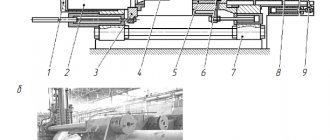
Figure 1 shows a general diagram of the proposed device.
In Fig.2, supply unit A.
The device for local ventilation of workplaces contains a supply air line 1, a supply nozzle 2 and an air inlet with an outlet pipe 3. The outlet pipe 3 of the air inlet is installed inside the inlet nozzle 2 coaxially to it to form an annular supply channel 4, which at the outlet has a confuser nozzle 5, profiled as confuser part of the Laval nozzle. The inlet nozzle 2 and the outlet pipe 3 are installed to move relative to each other. One of the embodiments is to move the wall of the supply nozzle 2 relative to the stationary outlet pipe 3. To do this, the outer wall of the supply nozzle 2 has a movable shell 6, which moves along the wall of the supply nozzle 2 along the groove 7 and is fixed with an adjusting screw 8.
It is possible to move the outlet pipe 3 relative to the stationary supply nozzle 2 (this embodiment is not shown).
The device works as follows.
Through the supply air line 1, fresh air is supplied to the supply nozzle 2, from where, through the annular supply channel 4 formed by the supply nozzle 2 and the outlet pipe 3 of the air intake, in the form of an annular jet, it is supplied to the zone of release of harmful substances. Along the outer perimeter of the zone of release of harmful substances, an annular curtain is formed that localizes harmful substances. Reflecting from the working surface, part of the air of the annular curtain, together with harmful emissions, is directed to the outlet pipe 3. Converging nozzle 5, profiled in the form of a confuser part of the Laval nozzle, contributes to the formation of a stable annular jet, which increases the efficiency of localization of harmful emissions. Depending on the nature of the technological process and the area of release of harmful substances, the cone of the annular jet is adjusted by moving the shell 6 of the supply nozzle 2 relative to the outlet pipe 3 with the screw 4 loosened. When the shell 6 moves relative to the outlet pipe 3, the spray angle vector of the annular curtain will change and, Accordingly, the localization area of harmful emissions will change.
A device for local ventilation of workplaces, containing an inlet nozzle and an air inlet with an outlet pipe, characterized in that the outlet nozzle of the air inlet is installed inside the inlet nozzle coaxially with it to form an annular inlet channel, while the annular inlet channel at the outlet has a confuser nozzle, for example in the form of a confuser parts of the Laval nozzle, and the supply nozzle and outlet pipe are installed to move relative to each other.
Non-jet nozzles
A person produces a supersonic flow with a Laval nozzle almost everywhere where he uses it. In turbines, Laval slot nozzles accelerate the flow to the rotor blades. In supersonic jet turbines, the channels between the blades of the moving disk are also Laval slot nozzles, which accelerate the gas to supersonic speed. Each two adjacent blades form with their surfaces a channel of a flat Laval nozzle, bent back at an angle. The flow in it accelerates and flows back to the movement, creating a reactive force for the blades. Supersonic turbines are used in aviation and astronautics, ground technology and navigation, energy and energy resource extraction.
You can grind the material with a supersonic flow, obtaining a fine mill. Bulk material enters the supersonic jet. It is captured and accelerated by a jet hitting a solid barrier, and breaks against it at a speed of many hundreds of meters per second. High purity of grinding - the material itself is crushed against the barrier - allows you to grind medicines or chemicals of a high degree of purity.
- Aerion has begun aerodynamic tests of a model of a “quiet” supersonic aircraft
Aerion Supersonic has begun aerodynamic testing of a model of a promising supersonic business jet. The first flight of the aircraft could take place in 2025.naked-science.ru
Supersonic wind tunnels also use a Laval nozzle. The most common type of supersonic tube is a balloon tube. In a large room there are two or three rows of thick steel cylinders, two stories high, covered by a second floor of shelving (to reach the top of the cylinders when needed). A couple of days before purging, the cylinders are pumped with air all day long, accompanied by the hum and vibration of the compressor. Their bodies heat up greatly from compression far beyond a hundred atmospheres, then cool down overnight.
Blowing is carried out in a separate box with steel doors. All the air stuffed into the cylinders is released in thirty seconds. The nozzle converts the compressed air of the cylinders into a supersonic flow flowing in the working part of the pipe. It has a small cross-section and is assembled from durable steel elements that enclose the flow with the blown model. A bonus is the simulation of supersonic flight at high altitude with its frost - due to the expansion of the flow, the temperature in the working part is minus 80 degrees. The Mach number of the flow in the pipe can exceed 5, then the pipe becomes hypersonic.
NASA's Jet Propulsion Laboratory (JPL) hypersonic wind tunnel, built in 1959. It operated in a speed range from Mach 4 to Mach 11. A JPL engineer sets up a model rocket in the test section. The two horizontal stainless steel plates were flexible and could be moved by a system of hydraulic jacks, visible from above and below, to change the speed and other parameters of the air flow. Photo: NASA.
In one of the Moscow universities with a vast but intricate courtyard, in one of its nooks there was a lattice booth similar to a kiosk. The lecture halls of the English Department opened onto this part of the courtyard. Once a week, classes were interrupted for half a minute by a wall of continuous noise, completely drowning out any attempts at speech by teachers and students. A lattice booth hid the exit channel of the supersonic pipe of this university, flooding the courtyard with a roar during purging. Thus, supersonic aerodynamics invaded all areas of science that came out as audiences to this booth.
The pioneer of supersonic calculations and the founder of supersonic aerogasdynamics, Ludwig Prandtl, was able to calculate a nozzle that gives the required Mach number at the available flow rate. In 1909, he built the world's first supersonic tube in Göttingen, Germany, where he worked. Today, all nozzles are calculated according to his method of calculating a supersonic nozzle.
Calculations allow you to profile the nozzle. The profile is the curvature of the nozzle shape, distinguishing it from a simple cone, the exact geometry of the nozzle. At the critical section, the expansion of the gas is most intense, and immediately after it it is necessary to quickly give the gas a volume for expansion. The walls of the nozzle here diverge to the sides with a steeply expanding bell. At the end of the nozzle, when the work of expansion is done, the flow is directed by the cylindrical edge of the nozzle into a nearly parallel jet.
The smooth transition from the sharply expanding part to the almost cylindrical edge makes the nozzle convex, similar to a glass or bell. This will be the profiled nozzle. Correctly selected wall curvature will expand the gas optimally, with the greatest flow acceleration at the shortest nozzle length. These are the minimum mass, cooling surface, volume of material and processing, and cost. That's why almost all nozzles today are profiled. Their profile is calculated based on the given parameters of the source gas and the desired flow, allowing the best curvature of the vessel for supersonic to be sculpted.
Nozzle for sandblasting machine. How to find the most durable one?
High-quality surface cleaning of metal surfaces with a concentrated jet of sand is impossible if the parameters of the nozzle - the output part of the device - are incorrectly determined.
The nozzle for a sandblaster is its fastest-wearing part, the durability of which, depending on the material and consumption of the air-sand mixture, does not exceed 800...1000 hours, given that it is correctly selected.
Our article will talk about choice today.
Typical nozzle design
The simplest nozzle for a sandblasting machine is a hollow tube with a threaded part at one end, which is designed to connect the part to the nozzle holder.
The main geometric characteristics of industrially produced replacement nozzles:
- The diameter of the connecting thread (depends on the technical characteristics of the sandblasting machine, but a 2" or 1¼" cylindrical pipe thread is usually used. It is also possible to connect the nozzle with the nozzle holder using a union nut and a sealing washer. Do-it-yourself nozzles are connected to the hose of the working unit using ordinary clamps.
- The length of the part, which varies in the range of 7…23 mm (shorter ones are used for cleaning less contaminated surfaces).
- The diameter of the internal hole at its minimum cross-section. Replacement tips are available with diameters of 6, 8, 10 and 12 mm.
- The inlet diameter of the nozzle, determined by the diameter of the connecting hose (it can be 25 or 32 mm).
The main parameter of the part under consideration is the profile of the internal hole, which determines the flow loss of the air-sand mixture, its speed at the inlet and outlet of the nozzle, as well as the value of the total hydraulic resistance, which ultimately determines the durability of the nozzle.
The simplest option (suitable for making it yourself) is a nozzle with a cylindrical internal hole of constant diameter. But to improve aerodynamic characteristics, two conical sections are sometimes made on such parts:
- Inlet confuser, the presence of which allows you to increase the energy of the flow of the mixture entering the nozzle;
- An output diffuser, the presence of which helps to increase the surface area processed simultaneously. In this case, the flow energy decreases, therefore, if higher-quality cleaning is necessary, a diffuser profile at the end of the nozzle is not always provided.
The most efficient internal orifice profile to ensure minimal flow loss is a Venturi profile sandblaster nozzle.
In this case, the hole consists of three interconnected sections, each of which performs certain functions:
- At the inlet of a nozzle with a Venturi profile there is a confuser expansion, the angle of which, however, is less than that of a confuser of a conventional nozzle (no more than 20...22º). The confuser part occupies up to 30% of the total length of the part.
- Cylindrical part, no more than 15% long.
- A diffuser part with a fairly small expansion angle (7...15º), the length of which is determined by the size of the nozzle itself in plan.
In order to reduce the hydrodynamic resistance of the working mixture that moves in the nozzle channel, all transitions from one part to the next are made with radius curves, the value of which is taken within the range of r = (0.02...0.03) d, where d is the diameter of the middle, cylindrical part of the nozzle.
How to choose a nozzle for a sandblaster?
A nozzle with a Venturi profile allows you to increase the speed of movement of the sand-air mixture by 2.5...3 times compared to nozzles with a different internal hole configuration.
A modern nozzle for a sandblasting machine with a Venturi profile is capable of ensuring the movement of particles at the outlet up to 700...720 km/h.
At the same time, the cleaning performance at the same mixture flow rates and pressures increases approximately 2 times.
Approximately, the selection of nozzle parameters can be made according to the following criteria:
- In terms of performance. With the required installation productivity of up to 10...12 m3/h, the internal diameter of the nozzle does not exceed 8 mm, with 12...22 m3/h - 10 mm, with higher productivity values, the diameter of the internal channel should be 12 mm;
- According to the highest air pressure. If it does not exceed 5 at, then the channel diameter can be taken as 6...8 mm, at pressures up to 7 at - 8...10 mm, at higher pressures - 12 mm;
- Depending on the specific consumption of abrasive. If this parameter does not exceed 200...250 kg/h, then a nozzle with a diameter of 6 mm is suitable, at 350...400 kg/h - 8 mm, at 600...900 kg/h - 10 mm, in other cases - 12 mm.
These recommendations apply to nozzles with cylindrical internal holes. To recalculate the given data for a nozzle for a sandblasting machine with a Venturi profile, the data on processing productivity should be increased by 35...50%, on flow rate - by 60...75%, and on pressure - by 15...20%.
An important element of choice is the nozzle material. Conventional high-carbon steels with increased abrasive resistance (for example, steels of type 75 or 65G) are not suitable for these purposes, since when hardened to maximum hardness they are characterized by increased sensitivity to impact loads, which inevitably arise at the initial moment of feeding the abrasive mixture into the nozzle.
Ceramic compositions have even less durability. For example, when making a nozzle with your own hands, they often use a used spark plug from a car engine as a starting material, removing the metal casing from it.
At the same time, they do not take into account that the ceramics in the spark plug design are designed to work with a gas flow in which there are no solid abrasive particles.
Therefore, the durability of such hand-made ceramic nozzles does not exceed several hours.
More efficient is the option with carbide nozzles, which are made of tungsten carbide. The surface hardness of such products reaches 85...90 HRA, with a surface bending strength of up to 1400...1600 MPa.
The disadvantage of such solutions is the high sensitivity carbides to temperature. When the temperature rises to 80...100ºС (which is quite likely during long-term sandblasting), temperature cracks may appear on the surface of the nozzle.
The durability of nozzles made of hard alloys reaches 750...800 hours.
The best option is to make a nozzle from boron carbide. With approximately the same hardness and strength, boron carbides are distinguished by their high resistance to temperature changes, therefore they retain their functionality at temperatures of 600...750ºС.
It is also interesting to compare prices for sandblasting nozzles. Industrial products made of boron carbide, depending on the length, profile and diameter of the internal hole, can be purchased for 1200...1600 rubles, and carbide nozzles - for 2500...7000 rubles.
Cavitation heat generator: review of models and DIY production
Various ways to save energy or obtain free electricity remain popular.
Thanks to the development of the Internet, information about all kinds of “miracle inventions” is becoming more accessible.
One design, having lost popularity, is replaced by another.
Today we will look at the so-called vortex cavitation generator - a device whose inventors promise us highly efficient heating of the room in which it is installed.
What it is? This device uses the effect of heating a liquid during cavitation - a specific effect of the formation of steam microbubbles in areas of local pressure reduction in the liquid, which occurs either when the pump impeller rotates or when the liquid is exposed to sound vibrations. If you have ever used an ultrasonic bath, you may have noticed how its contents noticeably heat up.
The reality of using cavitation for heating
There are articles on the Internet about rotary-type vortex generators, the principle of which is to create areas of cavitation when an impeller of a specific shape rotates in a liquid. Is this solution viable?
Let's start with theoretical calculations.
In this case, we spend electricity to operate the electric motor (average efficiency - 88%), and partially spend the resulting mechanical energy on friction in the seals of the cavitation pump, and partially on heating the liquid due to cavitation.
That is, in any case, only part of the wasted electricity will be converted into heat.
But if you remember that the efficiency of a conventional heating element is from 95 to 97 percent, it becomes clear that there will be no miracle: a much more expensive and complex vortex pump will be less efficient than a simple nichrome spiral .