A compressor is a device in which air or other gas moves under the influence of compression force. Such a device is included in the design of pneumatic tools and other equipment. Devices with a compressor are used in industrial production, household supplies, construction and repair work. In this case, the most significant parameter is the compression force of the gaseous substance. How the compressor creates pressure, how and how to regulate it, will be discussed in this material.
Compressor - device and principle of operation
The name of the device in question comes from “compressio”, which is translated from Latin as “compression”. The main purpose is to compress a gaseous substance in order to move it and use pressure force .
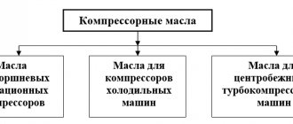
Pressure compressors produced by modern industry are divided into several types and subtypes. Based on the method of gas compression, two large groups of devices are distinguished: volumetric and dynamic. The pressure in them is created by different methods, and accordingly the principle of operation is different.
The design of volumetric models consists of working chambers with a system of valves in which the process of compression and movement of gas is carried out. Schematically, the principle of operation looks like this: the working substance enters the chamber through the inlet valve, which opens only inward and prevents gas from escaping outward. The gas is then compressed by reducing the volume of the chamber and pushed to the outlet valve, which also opens in one direction - outward.
Dynamic designs compress gas by accelerating its movement using a screw system. As a result, the energy of motion is converted into compression force.
On a note! In addition to the principle of operation, compressor devices are divided into groups according to the type of working substance (air, steam, any gas or a mixture of them), the type of drive, the method of heat removal, the industry used, and the final pressure.
Operating principle
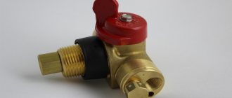
The pressure switch for the compressor controls the piston unit and maintains optimal pressure inside the receiver. Sometimes you can find such a unit on screw devices - it will be responsible for performing compression of air masses and their correct supply.
Taking into account the force of the pneumatic automation press, the device acts on the live line. Lack of pressure starts the motor, and when the specified parameters are reached, it turns it off. We are talking about a standard operating scheme, which involves connecting to a closed circuit network.
The role of the air pressure switch
The design of the ejector includes an air-filled cylinder with a given pressure. A decrease in performance requires turning on the engine and restoring the level. In the reverse situation described above, an excess will be recorded. The air supply will stop, otherwise the container will burst. The pressure switch is responsible for controlling these processes.
How do stiffener springs work?
There are modifications with a different working algorithm. By achieving minimum values in the compression circuit, the pressure switch turns off the electric motor, and at maximum values, it activates it. That is, the system operates only in an open circuit of the device.
The main working unit is springs with different stiffnesses. They reproduce the standard reaction to oscillatory movements inside the node. During the operation of the system, the indicators that are obtained when compressing and stretching the springs, that is, changing their sizes and shapes, will be measured. The changes are monitored by a spiral equipped with a relay unit. It disconnects or connects power lines if necessary.
There is no regulatory influence in the spring blocks; the main effect is on the motor. The user can set the peak values that are optimal for themselves; as the maximum is reached, the spring mechanism is activated.
Types of compressor pressure
Depending on the degree of gas compression and the maximum achieved value of this parameter, there are the following types of devices:
- vacuum devices - used for pumping out air;
- low pressure devices (with an indicator of up to 1.5 MPa) - used in sets of professional pneumatic equipment, household pneumatics and cleaning equipment;
- units of medium compression ratio (over 1.5 MPa to 10 MPa) - used in the mining industries, in industrial refrigeration units, air conditioners, refrigerators, in automated starting systems and devices, as well as other industries;
- installations of a high degree of pressure increase (over 10 to 100 MPa) - such equipment is equipped with automation that regulates the compression ratio and is used in many industries;
- ultra-high pressure devices (from 100 MPa) - used in metallurgy and other large industrial production.
Operating pressure
An important technical characteristic of any compressor model is the operating pressure - this is the level of air compression that the device can create and constantly maintain . The value is measured in MPa, bar, kg/cm 2, atmospheres, as well as mmHg. For example, the documentation may indicate 7 bar or 15 MPa.
The operating scheme for all automatically controlled compressors is common: the device sucks in air until it reaches the required amount. Then, by stopping the rotation of the electric motor, the air injection stops. As soon as the device reduces the pressure to the minimum permissible value, the engine starts working, thereby starting the process of compressing air to maximum levels.
The on/off cycle of the compressor is controlled by a special device called a pressure switch. It is this element that works as a time relay, closing/opening the engine power supply circuit at the right moment, and also performs the function of pressure control.
On a note! The difference between the minimum and maximum compression ratio for each model must be adjusted by the manufacturer.
First option
The operation scheme of all compressors is the same. After the required amount of air has been collected, the automatic control element weakens and stops air intake. An air pressure controlled relay works on the principle of pressing air onto a membrane and counteracting an elastic spring.
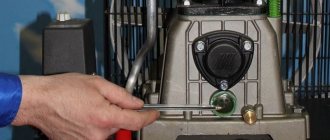
To manually adjust the compressor pressure, there is a switch in the form of a bolt or nuts that allows you to adjust the pressure of the unit. To access it you need to do the following:
- remove the protection in the form of a casing;
- the compressor pressure is adjusted by rotating either a bolt or two nuts, which increase or decrease the spring pressure force;
- There is a nut nearby for adjusting the differential pressure on and off;
- turn the pressure adjustment bolt to change the indicators, determine the desired indicator experimentally.
Automatic operating pressure block - operating principle
The operating principle of the automatic compression control unit is based on the physical law of resistance of two forces: the gas pressing on the membrane and the elasticity of the spring. It is possible to adjust the operating pressure, if necessary, using the threaded bolts provided in the pressure switch design, which can adjust the position of the spring. The air pressure regulators are located under the cover of the pressure switch, next to them there are direction indicators for where to tighten the spring. There is also a bolt responsible for the difference between the maximum and minimum compression ratio.
At the inlet of the air duct to the compressor there is a special valve that prevents gas from flowing in the opposite direction. The tightness of the housing, as well as the check valve, ensure a constant compression ratio at the outlet. To adjust the gas compression at the outlet, the device is equipped with a reducer. A pressure reducing valve is located here, allowing you to adapt the compressed air to the tool connected to the compressor, for example, a spray gun or a jackhammer. For visual control purposes, the devices are equipped with a pressure gauge to measure pressure.
System supercharger does not start
If the engine does not start and does not hum, it means that there is no supply voltage supplied to it. First of all, you should use an indicator screwdriver to check the presence of “zero” and “phase”, as well as the reliability of the connection between the plug and the socket. If there is poor contact, measures are taken to ensure a tighter fit. If there is 220 V at the input of the circuit, the fuses of the compressor unit are looked at.
Failed ones are replaced with passive protection devices of the same rating as the defective ones. Under no circumstances are hot-melt inserts designed for higher electric currents allowed. If the fuse blows again, you should find out the cause of the failure - there is probably a short circuit at the input of the circuit.
Pressure adjustment
During the operation of various air compresses, for example, in paint machines with a jet of liquid paint ejected under pressure, in aquarium or automobile models, it becomes necessary to regulate the pressure supply.
On a note! If a relay is used, you will have to change the factory settings of the device taking into account the range of compressor parameters.
To set the compressor to other operating parameters, you need to use a pressure gauge to determine the pressure readings when the automation turns the electric motor on and off. Next you need to adhere to the following algorithm of actions:
- disconnect the compressor from the electrical network;
- remove the pressure switch cover;
- turn the maximum compression regulator (P +/-) in the desired direction to decrease or increase the pressure value at which the relay turns off the electric motor;
- using the ΔΡ regulator with an arrow, if necessary, you can set the value of the difference in the compression ratio to start and stop the work process;
- return the relay cover to its place;
- connect the device to the network and turn it on.
You need to understand that the higher the compression ratio difference parameter is set, the less often the engine will turn off, and the pressure drop in the device will increase.
Selecting a compressor based on outlet pressure
Compressed air has energy. The compressor, which produces compression, is a necessary element in pneumatic equipment and devices where this force is needed.
Important! Select a compressor with characteristics that meet your specific output pressure needs. In other words, the tool and the compressor must match the parameters.
The correspondence of the compression ratio of the gas of the compressor and the device working with it in conjunction must be observed for the following reasons. Too high an output pressure is fraught with rapid wear of tool parts, and, as a result, leads to malfunctions of the working apparatus. And when the compressor does not pump up enough output pressure, this leads to the opposite problems: the tool does not gain the required operating power or does not start. Therefore, the first rule of choice is that the degree of air compression at the outlet of the compressor must correspond to the maximum permissible value specified by the tool manufacturer, taking into account corrections for the length and diameter of the connecting line within 1 bar (0.1 MPa).
Stock requirement
The second rule for choosing compressor equipment concerns the performance parameter and the need for reserve. This characteristic determines the amount of air compressed per unit time. If you make the wrong choice, problems cannot be ruled out when a compressor that is weak in performance, even at the limit of its capabilities, does not produce the required pressure, and the tool “suffocates.” Therefore, it is logical to choose a device with a performance reserve.
Advice! According to the recommendations of experts, the optimal choice is when during operation of the equipment 70-80% of the maximum compressed air produced by the compressor is consumed.
Inlet air pressure characteristic
World standards provide for marking the air performance of compressors in a free “loose” state. In the device passport, most manufacturers indicate the volume of air at the inlet, which corresponds to generally accepted rules . When choosing a compressor, you should take into account the fact that during compression some losses in the outlet pressure indicator are inevitable.
On a note! Note that domestic manufacturers, as a rule, report the compressor output performance in the characteristics.
So, methods for compressing a working gaseous substance in a compressor in order to increase its pressure to the level required by a specific tool were described above. All necessary information is indicated in the accompanying documentation for the compressor equipment. But it should be taken into account that the performance given in the characteristics was measured by the manufacturer at a temperature of 20 0 C, so using the device in cooler conditions will lead to a decrease in the indicator. And to find out the actual parameter, you need to multiply the theoretical one (from the instructions) by the efficiency.
Maintenance
From a maintenance point of view, oil compressors are more difficult than oil-free ones. At the same time, devices of the first type are more durable and are also able to work much longer without interruption . Therefore, it is recommended to purchase oil devices for home, and their cost is an order of magnitude lower. They are suitable, for example, for an airbrush for painting small parts or for other purposes. Oil-free compressors are used in cases where oil is not allowed to enter pneumatic equipment.
Maintenance of oil equipment
Oil compressors (for example, Remeza brand) require regular maintenance. Replacing and monitoring the oil level, cleaning and periodically purchasing new filters (air and oil) is not a complete list of work that needs to be carried out for this type of device in order to avoid their breakdown and subsequent repairs.
Maintenance of oil-free equipment
If you use oil-free equipment correctly, you will need to carry out its maintenance much less frequently than in the previous case.
On a note! The only consumables for oil-free devices are air filters.
Daily care
Daily maintenance of compression equipment includes the following:
- Visual inspection. You need to check the compressor for dents and other external defects and make sure that the ground is securely fastened. Next, you should make sure that the power cable, safety valve, pressure gauge and pressure switch are intact and in good working order.
- Checking the oil level through the inspection window - the fluid should be at the red mark level. If this is not the case, it needs to be topped up. If the consistency and color of the oil changes, it is necessary to change it completely. During operation, liquid should not come into contact with the external parts of the compressor. The same brand of oil should be poured into the device as previously. You cannot mix products of different brands, varieties and properties. You need to follow the manufacturer's recommendations - usually the instructions indicate what type of oil to pour into a specific compressor.
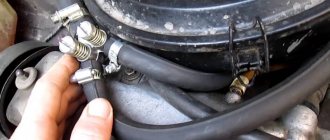
- Inspection of air ducts. You need to make sure that they are tightly connected and there is no air leakage. At this time, the equipment should be turned off, and the pressure in the receiver should not exceed the reading of 0.5-0.7 MPa. There should be no air noise in the connections; if necessary, they should be tightened.
- After work, it is necessary to drain the condensate through a special outlet installed in the lower part of the receiver. Failure to comply with this rule will result in liquid entering the pneumatic line, and rust and metal corrosion will appear in the receiver.
- Finally, the compressor must be cleaned of dirt and dust. This applies to all external surfaces, the piston block and the electric motor. This procedure is necessary to better cool the compressor and extend its service life.
All of the above points apply to oil-type compressor equipment. And for daily maintenance of oil-free devices, you only need to skip point B.
Scheduled maintenance
A routine inspection of a new device is carried out at the break-in stage - after the first 8 hours of operation after installation and startup . Maintenance consists of checking how the piston block cylinder head bolts are tightened. This is necessary to compensate for temperature shrinkage.
The next inspection is carried out within the first 50 hours after the compressor is put into operation. At the same time, the cylinder head bolts are re-inspected. Next, the belt tension is checked and, if necessary, adjusted. Belts are cleaned of dirt.
Important! The belts should not be allowed to be overtightened or undertightened, as this will lead to equipment failure.
After the first 100 hours of operation of the device, the oil must be changed, and further refueling is carried out every 300 hours. It is also necessary to check the condition of the intake air filter. If necessary, the part is cleaned or replaced with a new one. At the same time, they check the belt tension, and also inspect the electric motor, platform, piston block and test the strength of their installation.
Important! The intake air filter must be replaced every 600 hours. And every 1200 hours, the check valve is disassembled and cleaned from dirt.
Major renovation
The procedure for overhauling compressor equipment includes a complete disassembly of the device, replacement of the crankshaft bearings, calibration of the shaft journal, checking of components and moving connections, parts, as well as other work to restore the factory parameters of the device and ensure its reliable operation until subsequent scheduled repairs.
The most reliable compressors
Compressor PATRIOT Euro 24-240 on Yandex Market
Compressor Denzel PC 50-260 on Yandex Market
Compressor Metabo Basic 250-24 W on Yandex Market
Compressor Quattro Elementi KM 24-260 on Yandex Market
Compressor Quattro Elementi KM 50-380 on Yandex Market
One of the main indicators of air compressors is operating pressure. In other words, it is the level of air compression created in the receiver that must be maintained within a certain range. It is inconvenient to do this manually, referring to the indicators of the pressure gauge, so the compressor automation unit is responsible for maintaining the required level of compression in the receiver.
Diagrams for connecting the pressure switch to the compressor
The connection of the relay that controls the degree of air compression can be divided into 2 parts: the electrical connection of the relay to the unit and the connection of the relay to the compressor through the connecting flanges. Depending on which motor is installed in the compressor, 220 V or 380 V, there are different connection diagrams for the pressure switch. I am guided by these diagrams, provided that you have certain knowledge in electrical engineering, you can connect this relay with your own hands.
Connecting the relay to a 380 V network
To connect the automation to a compressor operating from a 380 V network, use a magnetic starter. Below is a diagram of connecting automation to three phases.
In the diagram, the circuit breaker is indicated by the letters “AB”, and the magnetic starter by “KM”. From this diagram it can be understood that the relay is set to a switch-on pressure of 3 atm. and shutdown - 10 atm.
Connecting the pressure switch to a 220 V network
The relay is connected to a single-phase network according to the diagrams given below.
These diagrams indicate various models of pressure switches of the RDK series, which can be connected in this way to the electrical part of the compressor.
Connecting the pressure switch to the unit
Connecting a pressure switch to a compressor is quite simple.
- Screw the pressure switch onto the receiver pipe using its central threaded hole. For better thread sealing, it is recommended to use fum tape or liquid sealant. The relay can also be connected to the receiver through a reducer.
- Connect a relief valve to the smallest output from the relay, if present.
- The remaining outputs from the relay can be connected to either a pressure gauge or a safety relief valve. The latter is installed without fail. If a pressure gauge is not required, then the free output of the pressure switch must be plugged with a metal plug.
- Next, wires from the electrical network and from the engine are connected to the sensor contacts.
After the complete connection of the pressure switch is completed, it is necessary to configure it for proper operation.
Troubleshooting methods
A more difficult problem lies ahead if the compressor does not work. There may be several sources. Let's consider one of them - melting of the pressure switch contacts due to erosion arising from electrical sparks.
Burning of the contact group occurs due to electric spark erosion, which is formed as a result of the opening of the contacts. However, it is not always possible to replace elements - some modifications are no longer available for sale
To eliminate this type of malfunction, you can use one of the following methods: clean the surface, which extends the service life by at least 3 months, or repair it by replacing the contacts in the terminal clamps.
Step-by-step instructions for the second option:
- Bleed all air from the receiver and turn off the power to the ejector. Remove the pressure switch.
- Having removed the protective housing, disconnect the wiring connected to the group of contacts.
- Using a screwdriver, you need to remove the terminal with contacts and drill out the burnt lines from it.
- You can replace the wire with copper wire. It is necessary to select it taking into account the diameter of the hole, since it must fit tightly into the seat. It is inserted into the hole and pressed on both sides.
- Similar actions are performed with the remaining burnt lines.
- After the contact group is assembled, it is mounted in its original place and the pressure switch cover is screwed on.
The compressor relay operates in difficult conditions, subject to wear and failure.
Although the repair is not cost-effective, those familiar with the device can perform the repair themselves. However, the option of replacing it with a new device still remains profitable.
Adjusting the compressor pressure
As mentioned above, after creating a certain level of air compression in the receiver, the pressure switch turns off the unit’s engine. Conversely, when the pressure drops to the switching limit, the relay starts the engine again.
Important! By default, relays, both single-phase devices and units operating from a 380 V network, already have factory settings. The difference between the lower and upper engine start threshold does not exceed 2 bar. It is not recommended for the user to change this value.
But often situations that arise force you to change the factory settings of the pressure switch and adjust the pressure in the compressor at your discretion. You can only change the lower switching threshold, since after changing the upper switching threshold upward, the air will be released by the safety valve.
Pressure adjustment in the compressor is carried out as follows.
- Turn on the unit and record the pressure gauge readings at which the engine turns on and off.
- Be sure to disconnect the device from the power supply and remove the cover from the pressure switch.
- After removing the cover, you will see 2 bolts with springs. The large bolt is often designated by the letter “P” with the signs “-” and “+” and is responsible for the upper pressure, upon reaching which the device will be turned off. To increase the level of air compression, turn the regulator towards the “+” sign, and to decrease it, turn towards the “-” sign. First, it is recommended to make half a turn with the screw in the desired direction, then turn on the compressor and check the degree of pressure increase or decrease using a pressure gauge. Record at what indicators of the device the engine will turn off.
- Using a small screw you can adjust the difference between the on and off thresholds. As mentioned above, it is not recommended that this interval exceed 2 bars. The longer the interval, the less often the device’s engine will start. In addition, the pressure drop in the system will be significant. Setting the on-off threshold difference is done in the same way as setting the upper on-off threshold.
Purpose
The function of air compressors is to produce a stream of air with a certain pressure; it must be stable and uniform. It should also be possible to change the parameters of this jet. Each compressor has a reservoir (cylinder) for air. It must have the required pressure. When it drops, turn on the engine to replenish the air supply. If there is excessive pressure, the air supply should be stopped to prevent the container from bursting. This process is controlled by a pressure switch.
When it functions correctly, the engine is preserved, it is protected from frequent switching on and off, and the operation of the system is uniform and stable. The container membrane is connected to the pressure switch. By moving, she can turn the relay on and off.
Principle of operation
Taking into account the amount of pressure in the system, the relay serves to open and close the voltage circuit; if the pressure is insufficient, it starts the compressor and turns it off when the parameter rises to a predetermined level. This is a normally closed loop operating principle for motor control.
The opposite principle of operation is also encountered, when the relay turns off the electric motor at minimum pressure in the circuit, and turns it on at maximum. This is a normally open loop circuit.
The working system consists of springs of different levels of rigidity that respond to changes in pressure. During operation, the deformation forces of springs and compressed air pressure are compared. When the pressure changes, the spring mechanism is activated and the relay closes or opens the electrical circuit.
Accessories
The air compressor relay may contain the following components:
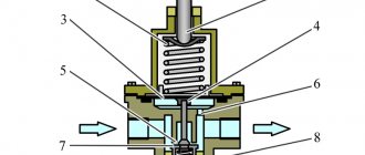
- Unloading valve. It is located between the compression chamber and the compressor check valve. When the engine stops, this component is activated and removes excess pressure from the piston block. When the engine starts, the pressure generated closes the valve, making it easier to start the unit. Some unloader valves have delayed activation. When starting the engine, it assists the engine by remaining open until the system reaches a predetermined value. During this time, the engine reaches maximum speed.
- Mechanical switch. Serves to enable and disable automation. The switch usually has two positions. When the mode is turned on, the automation is activated, the compressor is connected to the network and turned off, taking into account the specified pressure parameters in the system. In the OFF position, no power is supplied to the drive.
Pressure switch for air compressor
Thermal relay. It protects the electric motor by limiting the current so that the motor windings do not burn out. The required current strength is set using a regulator. If the set value is exceeded, the engine will be disconnected from the network. Safety valve. Protects the system in case of improper functioning of the pressure switch. When the pressure is exceeded, if the relay does not operate, the safety valve is activated, which relieves the pressure. This allows you to avoid accidents when the control breaks down.
How to set the compressor to turn on automatically?
This function works on air compressors “by default”. Piston compressors have an intermittent operating mode. The engine turns on automatically and drives the injection pistons when it is necessary to pump air into the receiver. Having provided the specified pressure in the pneumatic system, the installation is turned off.
Controls the mode of the compression relay (pressostat). This device gives a control command to the engine when the pressure in the pneumatic system reaches a predetermined value. When the maximum is reached, the relay switches off the engine and the pumping stops. When the compression ratio drops to a predetermined minimum, the pressure switch turns on the electric motor to pump air into the system.
The question of setting it to turn on automatically arises if there are problems with the pressure switch. It's usually not a question of the engine turning on at all. It is often necessary to configure automatic activation at the desired compression level of the working environment.
Principle of operation
The operating principle of the automation unit is simple. The device is mounted on a pipe communicating with the receiver. The spring-diaphragm pressure switch sensor for the compressor continuously measures the pressure. As soon as it drops below the set value, the sensor rod, under the action of a spring, closes the contacts of the compressor relay and the electric motor is connected, pumping air into the tank. After reaching the set pressure, it presses the rod and opens the contacts, turning off the engine. Adjustment of these values is available to the user. In addition, when the operating pressure limit is reached, the safety valve included in the device is activated, releasing excess air from the compressor into the atmosphere.
How to set the compressor to the desired pressure?
Compressors are supplied with factory settings for switching on and off. As a rule, buyers decide to change standard settings for two reasons.
First: such changes are dictated by the technical characteristics of the connected instrument.
Second: the desire to save energy and reduce the load on the pneumatic system.
For example, a pneumatic tool is connected to the system, whose maximum pressure threshold is lower than that set on the injection unit. If you do not reduce the compression level, the tool will fail. You can use a pressure reducing valve to adjust the degree of compression of the air supplied to the pneumatic system, but this will be a half-measure. Why force the compressor unit to work with force, pumping more than necessary?
Another case: the relay is activated at a minimum compression of 8 atmospheres, and a value of 6 bar is sufficient for the connected pneumatic tool to operate. By setting the compressor to a lower pressure, you can save up to 10% in energy. The load on the pneumatic system: pipes, hoses, fittings, fittings is reduced.
To set the compressor to the desired pressure, you need to change the pressure switch settings. You should interfere with the functionality of this device only if there are no other solutions to the problem. It is better to entrust this work to a specialist.
Essential Security
Tips in the article “Why do you need a screw compressor” here.
This ability to regulate pressure is present on all units that use compressed air energy for production. Plus, the gearboxes of such machines provide pressure control at all stages in order to ensure the safe operation of all parts of the working structure.
Finished compressors are delivered to customers with factory settings. Developers optimize the operating mode of the unit to extend its life, increase productivity and simplify maintenance. Sometimes it is necessary to decide how to configure a compressor so that it meets operating conditions that differ from conventionally standard ones. Manufacturers allow some changes, describing in the instructions exactly which settings can be adjusted.