Introduction
Studying the fundamentals of liquid and gas physics plays an important role in obtaining the necessary skills to solve complex scientific and technical problems that require the construction of physical models of a variety of hydro-gas-dynamic systems.
The objects of study are pipelines and sections of pipelines through which gas and liquid move, as well as the Loval nozzle.
The purpose of the work is the formation of systematized knowledge in the field of phenomena related to the patterns of gas movement as it flows through channels. The skills acquired during the solution will prepare the future specialist for further scientific and educational activities.
In this course project, problems are constructed that involve the calculation of branched and short pipelines, Laval nozzles. Based on the calculation results, the necessary parameters for the normal functioning of these systems are determined. Based on these parameters, the optimal operating mode of the system is selected.
The numerical solution was obtained by the establishment method using the flow continuity and Mendeleev-Clayperon equations.
Motor housing
Based on the data obtained on the gas pressure in the combustion chamber, it was necessary to select a material for the housing that would meet these requirements.
Our peak pressure reaches almost 25 bar. Without further ado and trying to avoid using complex materials where possible, we decided to adopt a DU-40 steel pipe with a wall thickness of 3 mm. The corresponding pipe was successfully purchased from the first rolled metal product available on the market. Unfortunately, the warehouse for the iron workers' products was located in the open air, so the pipe was somewhat rusty. Cleaning with sandpaper and a “petal stick” by Lyosha (we say hello to Doctor Dew) did not give the normal effect, and I was too lazy to spend time on it. Why not try the chemical method for this. Of the chemicals that were within walking distance, there was only vinegar essence, citric acid and salt, all purchased at the nearest grocery store. As luck would have it, there was no suitable basin into which to pour the nuclear mixture and soak the pipe, I had to build it using the dendrofecal method from other boxes, using them as a support, and between them make a bath from the film left over from the airship, which was secured with stationery clamps. We put a pipe in this crispy sarcophagus and filled it with acetic acid, and for greater effect we added lemon and salt dissolved in water. The reaction began instantly. Satisfied with ourselves, we left the pipe to poison and left for the weekend with a clear conscience.
The smell that greeted us on Monday ate away at our eyes and nose. Yes, it was a shame they didn’t cover the bathtub with anything. The smell of vinegar seemed to have ingrained itself into the walls. Even wide open windows didn’t help, then we had to ventilate the studio for another two days, so don’t repeat our mistakes: it’s better to do such things either in the open air or in a tightly closed container. However, the result of cleaning the pipe was quite satisfactory: the pipe was cleaned both outside and inside. Keep in mind that after using chemical cleaning, you need to rinse thoroughly with water and wipe the item being cleaned dry, otherwise it will quickly become covered with a cloudy film in the air. Even better is to protect the surface from contact with air using paint, varnish or spray polyurethane. But these are purely our aesthetic considerations.
BIBLIOGRAPHICAL LIST
- Gritsenko, M.V. Hydrogasdynamics. Part 1. Textbook / M. V. Gritsenko, N. N. Khramtsova, A. V. Gritsenko. — Blagoveshchensk: Amur State. univ., 2008. - 75 p.
- Kovalnogo, N. N. Fundamentals of fluid and gas mechanics / N. N. Kovalnogo. - Ulyanovsk: Ulyanovsk State Technical University, 2002, -110 p.
- Krasnov N.F. Aerodynamics in issues and problems M. Higher school 1985.759c.
- Lapshev, N. N. Hydraulics: Textbook / N. N. Lapshev. - M.: Publishing House, 2007. - 272 p.
- Chass, S.I. Fluid mechanics in examples and problems: Textbook / S.I. Chass. - Ekaterinburg: Publishing House of the UGGU, 2006. - 216 p.
Nozzle calculation
The nozzle is the main element of the rocket engine (your CO), since, depending on the correctness of its calculation, you can get up to +30% thrust using the same fuel with the same channel.
We approached the calculation of the nozzle thoroughly, in detail about the mathematics of its calculation, the principle of operation, the ongoing processes, and in general, a lot of interesting things, you can read here and elib.osu.ru/bitstream/123456789/8572/1/1805_20110824.pdf. There is also a very convenient tool called Rocki-nozzle on the site (scroll down on the page and look for the corresponding link).
We download the program, substitute the calculated rocket values obtained in Meteor (see article) into the appropriate fields and get the nozzle profile at the output. We process the data and draw a beautiful nozzle in SolidWorks, observing all dimensions.
Next there was supposed to be a lathe, but it won’t be included in this issue, since my turner friend’s CNC machine refused to work and we couldn’t get to him. But by the next episode everything will definitely be there.
You can download the resulting model from the link at the end of the article.
Sandblasting nozzle: rules for choosing and making it yourself
The nozzle, which is used to equip a sandblasting machine, is the most important design element of such a device.
Only a correctly selected nozzle will allow you to most effectively use the sandblaster for its intended purpose: to clean various surfaces from dirt, old coatings, traces of corrosion, degrease them and prepare them for further processing.
For each application, you can select a nozzle of a certain diameter, depending on the fraction of sand used
The tasks that a sandblasting nozzle solves are to compress and accelerate to the required speed a mixture consisting of air and abrasive material, as well as to form a working spot and saturate it with abrasive acting on the surface of the workpiece.
Depending on the size of the surface to be sandblasted, different types of holes can be made in the nozzles.
Thus, for processing narrow surfaces, nozzles with the same diameter along the entire length are used, and for cleaning large surfaces, products are used, the holes in which have larger diameters at the inlet and outlet (Venturi type, developed in the middle of the last century).
The essence of sandblasting
Sandblasting involves exposing various surfaces to an abrasive material. Sand, shot, silicon carbide, small glass beads, etc. are used as the latter.
Sandblasting is a mechanical action on the surface of small solid particles
Before processing begins, the abrasive is placed in a sealed hopper. Air coming from a separate compressor is supplied through the main hose of the device under high pressure.
Passing by the opening of the intake hose, the air flow creates a vacuum in it, which facilitates the suction of abrasive into the main hose.
The air, already mixed with abrasive, is supplied to the gun, the main element of which is a sandblasting nozzle, through which the abrasive mixture is supplied to the surface being treated.
Layout of the sandblasting area
As mentioned above, various types of abrasives can be used to perform sandblasting. The choice here depends on the type of surface that needs to be cleaned.
Thus, treatment using sand is effective in cases where it is necessary to remove a layer of old paint from a concrete surface, clean brick walls from cement residues, and prepare metal parts for further painting.
Abrasives such as plastic or wheat starch are successfully used in the shipbuilding, automotive and aircraft manufacturing industries, with their help they effectively remove old coatings from composite materials.
Design features of a nozzle for a sandblasting machine
The main parameters of the nozzle installed on the sandblasting machine are:
- diameter and type of hole;
- length;
- manufacturing material.
Abrasive blasting nozzles of various configurations
The diameter of the hole in the nozzle, which is fixed on the sandblasting machine using a special nozzle holder, is selected depending on the performance the device should have.
The performance of any sandblasting machine - both serial and home-made - depends on the power of the jet or the volume of air that the nozzle is able to pass per unit time.
The power of the jet generated by the nozzle is directly proportional to the volume of air that passes through it per unit time. Accordingly, in order to increase the power of the sandblasting machine, it is necessary to make a hole of a larger diameter in its nozzle.
For example, you can estimate the power of nozzles whose holes have different diameters.
If a nozzle whose diameter corresponds to 6 mm (1/4 inch) has a power equal to 100%, then products with holes of larger diameters will differ in the following value of this parameter:
- 8 mm (5/16 inch) – 157%;
- 9.5 mm (3/8 inch) – 220%;
- 11 mm (7/16 inch) – 320%;
- 12.5 mm (1/2 inch) – 400%.
To better understand the power of a nozzle with a particular internal hole diameter, you can take into account that products with a diameter of 6 mm (1/4 inch) are capable of providing an average jet power of 30 m3/hour.
The table allows you to roughly estimate the effect of nozzle diameter and air pressure on productivity and abrasive consumption
If you are not going to make a nozzle for a sandblasting machine with your own hands, then you should keep in mind that mass-produced products have standard hole diameters of 6, 8, 10 and 12 mm.
The choice of a nozzle parameter such as its length is influenced by the degree of contamination of the surface being cleaned. For sandblasting surfaces that have minor contamination, shorter nozzles (7–8 cm) are selected.
If it is necessary to treat a surface on which there are complex contaminants, the length of the nozzle must be significant (up to 23 cm).
Shorter nozzles, installed in a standard nozzle holder, are also used in cases where hard-to-reach areas need to be treated.
Nozzles, the diameter of which does not change along their entire length, make it possible to ensure an exit speed of the abrasive material of 320 km/h, while the pressure of the mixture of air and abrasive coming from such a nozzle is 6 atm.
Nozzles with a Venturi channel form a jet of an abrasive mixture, the speed of which can reach up to 720 km/h. It is clear that nozzles with internal holes of this type increase the efficiency of sandblasting.
It is obvious that the flow area of the VENTURI type nozzle is significantly larger than that of a conventional straight line
The use of nozzles with Venturi-type internal holes allows enterprises and specialized companies not only to increase their productivity, but also to significantly improve the quality of the processing performed. What is important is that the use of products with such channels does not require the purchase of special abrasives and does not lead to an increase in compressed air consumption.
If nozzles with holes of the usual type for sandblasting machines can be made with your own hands (although this is difficult), then it is almost impossible to make products with a Venturi channel at home without special equipment.
Design of a sandblasting nozzle with a Venturi channel: d - internal diameter; D—inlet diameter; T - connecting thread; L—nozzle length
To make nozzles, including with your own hands, various materials can be used, the choice of which determines the durability of the product. Thus, depending on the material used, nozzles for sandblasting machines have the following durability:
- ceramic products that are made at home from ordinary spark plugs - 1–2 hours;
- cast iron nozzles – 6–8 hours;
- products for the production of which tungsten carbide was used – 300 hours;
- nozzles made of boron carbide - 750–1000 hours.
If steel shot, rather than sand, is used as an abrasive material in a sandblasting machine, then the durability of any type of nozzle increases by 2–2.5 times.
How to choose the right sandblasting nozzle
When choosing a nozzle for your sandblaster, consider the fact that the most inexpensive products are also the most short-lived. Such nozzles will ultimately cost you more than quality products, especially if you have a large amount of work to do.
Sandblasting Wear Resistant Tungsten Carbide Nozzles
Nozzles made of cast iron and ceramics are suitable for domestic purposes. Many home craftsmen even make ceramic nozzles on their own using used spark plugs. In order to make a nozzle from such a candle, it is enough to remove the metal electrode from its ceramic shell.
When using cast iron and ceramic nozzles for a sandblasting machine, it should be borne in mind that due to their accelerated wear, they increase the consumption of both air and abrasive, so they are not recommended for use when performing large-scale work.
Expensive boron carbide and tungsten carbide nozzles not only offer superior durability, but they can also be used with virtually any abrasive except carborundum and aluminum oxide.
This, in fact, explains the rather high cost of such nozzles for a sandblasting machine, which can last a very long time without losing their characteristics or increasing the consumption of abrasive material and air. The use of such products is advisable in all situations where a large amount of work is required to clean various surfaces.
Do-it-yourself Laval nozzle - Metalist's Handbook
To produce affordable building materials, various types of equipment are used, including a foam generator for foam concrete.
Despite the ease of manufacture and low cost, the technical requirements for foam concrete blocks are strict.
To achieve high quality in the production of this building material, it is necessary to strictly comply with all technological standards.
Purpose of the foam generator
Currently, foam concrete is in demand in individual construction as an affordable and high-quality material. This is due to its high performance characteristics.
Low-rise residential buildings, garages, country houses and various outbuildings are erected from foam concrete.
Foam blocks do not burn and are not subject to shrinkage; they are sufficiently resistant to any atmospheric influences.
In winter, buildings made of foam concrete retain heat well; in summer, such rooms are not hot. You can produce foam concrete yourself using a homemade foam generator.
:
The practice of recent years shows that more and more people are striving to build a house or garage on their own. This approach has become widespread due to technical capabilities.
Equipment for the production of foam concrete can be purchased at an affordable price or made independently.
One of the main elements of the installation is a foam generator. This device is used to ensure that the concrete block is saturated with foam, thereby giving the block its characteristics.
Today on the construction equipment market you can find and buy a foam generator suitable for power.
However, you can make a foam generator for foam concrete with your own hands without significant financial costs, which will reduce construction costs.
The quality of the foam that is formed in homemade foam generators is exactly the same as in factory ones.
Once you become familiar with the operating principle of such a unit, you can draw your own drawings and begin manufacturing.
The foam generator consists of the following elements:
- shut-off and control equipment;
- chamber for forming the mixture;
- nozzle.
The specific design of the foam generator may undergo changes, but the principle of operation remains the same.
Operating principle
The main function of the foam generator is to ensure the supply of foam to the sand-cement mortar prepared in advance.
To produce foam concrete, an ordinary concrete mixer is used. Concrete is mixed in it for pouring foundations and walls or mortar for brickwork.
When, during the process of mixing the solution, a certain amount of foam gets into it, ordinary concrete turns into foam concrete.
All specialists are aware of the advantages and disadvantages of foam concrete. Today, this building material can be prepared directly on the site where a house, garage or other object is being built.
Foam Generator Structure
When starting to make a foam generator with your own hands, you need to optimize all the drawings and descriptions that catch your eye.
The fact is that many specialists, having become familiar with the operating principle of a foam generator, immediately apply the acquired knowledge, turning it into reality.
Schemes and drawings:
A clear demonstration of the operation of a foam generator can be seen at any car wash.
The foam, when mixed, fills a certain volume of the concrete block and thereby reduces its original density.
The simplest foam generator can be assembled from the following elements:
- foam solution supply pipe;
- compressed air supply pipe;
- mixing chamber;
- foam cartridge.
Factory-made foam concentrate is always available on the shelves in building materials stores.
If this is not possible, then the emulsion can be prepared by mixing gum rosin, caustic soda and bone wood glue. The cooking process is not complicated, but requires care.
After the homemade foaming agent is ready, you need to check its quality. The foam must have sufficient density and durability.
Assembly and connection
The main elements of a foam generator for the production of foam concrete are a mixing chamber and a foam cartridge. In this context, it is important to emphasize that behind these terms lie ordinary elements that are well known to masters.
The mixing chamber is an ordinary pipe. The diameter of the pipe is selected depending on the power of the future generator. Two pipes are welded to the pipe.
:
The first is at the end, intended for air supply, the second is in the middle of the pipe at an angle of 90 degrees. A foaming agent solution is supplied through it. A shut-off valve must be installed on each branch pipe.
Foam generators for factory-made foam concrete are equipped with two valves - a shut-off valve and an adjustment valve.
The practice of recent years shows that for small production volumes, when it is necessary to produce foam blocks for the construction of a garage or country house, one shut-off valve is sufficient.
A pipe is welded to the second end of the mixing chamber, which serves as a foam cartridge. If possible, the inner surface of the pipe is treated in the shape of a funnel.
This is done to reduce the flow rate of the foaming agent and air mixture to ensure foam formation.
Some nuances
When the mixing chamber and foam cartridge are connected, an element called a Laval nozzle or another device, a nozzle, is fixed between them.
These elements are designed to increase the flow rate of the mixture during the transition from the chamber to the foam cartridge. It is in the foam cartridge that the final formation of foam occurs.
To make the process more efficient, the flow of the foaming agent is “broken” against a special filter.
In homemade foam generators, kitchen metal mesh, which is sold in every hardware store, is used as such a filter.
Building a foam generator with your own hands to produce foam concrete is not a difficult task. The main thing here is to understand the principle of operation of the generator.
:
A technically more difficult task is to correctly connect the foam generator to the main equipment.
Currently, the designs of concrete mixers that are used for the production of blocks can be found in a variety of ways.
Before assembling the foam generator, it is necessary to determine all the installation elements that are used when connecting hoses and pipes.
Sandblasting nozzle: rules for choosing and making it yourself
The nozzle, which is used to equip a sandblasting machine, is the most important design element of such a device.
Only a correctly selected nozzle will allow you to most effectively use the sandblaster for its intended purpose: to clean various surfaces from dirt, old coatings, traces of corrosion, degrease them and prepare them for further processing.
For each application, you can select a nozzle of a certain diameter, depending on the fraction of sand used
The tasks that a sandblasting nozzle solves are to compress and accelerate to the required speed a mixture consisting of air and abrasive material, as well as to form a working spot and saturate it with abrasive acting on the surface of the workpiece.
Depending on the size of the surface to be sandblasted, different types of holes can be made in the nozzles.
Thus, for processing narrow surfaces, nozzles with the same diameter along the entire length are used, and for cleaning large surfaces, products are used, the holes in which have larger diameters at the inlet and outlet (Venturi type, developed in the middle of the last century).
The essence of sandblasting
Sandblasting involves exposing various surfaces to an abrasive material. Sand, shot, silicon carbide, small glass beads, etc. are used as the latter.
Sandblasting is a mechanical action on the surface of small solid particles
Before processing begins, the abrasive is placed in a sealed hopper. Air coming from a separate compressor is supplied through the main hose of the device under high pressure.
Passing by the opening of the intake hose, the air flow creates a vacuum in it, which facilitates the suction of abrasive into the main hose.
The air, already mixed with abrasive, is supplied to the gun, the main element of which is a sandblasting nozzle, through which the abrasive mixture is supplied to the surface being treated.
Layout of the sandblasting area
As mentioned above, various types of abrasives can be used to perform sandblasting. The choice here depends on the type of surface that needs to be cleaned.
Thus, treatment using sand is effective in cases where it is necessary to remove a layer of old paint from a concrete surface, clean brick walls from cement residues, and prepare metal parts for further painting.
Abrasives such as plastic or wheat starch are successfully used in the shipbuilding, automotive and aircraft manufacturing industries, with their help they effectively remove old coatings from composite materials.
Design features of a nozzle for a sandblasting machine
The main parameters of the nozzle installed on the sandblasting machine are:
- diameter and type of hole;
- length;
- manufacturing material.
Abrasive blasting nozzles of various configurations
The diameter of the hole in the nozzle, which is fixed on the sandblasting machine using a special nozzle holder, is selected depending on the performance the device should have.
The performance of any sandblasting machine - both serial and home-made - depends on the power of the jet or the volume of air that the nozzle is able to pass per unit time.
The power of the jet generated by the nozzle is directly proportional to the volume of air that passes through it per unit time. Accordingly, in order to increase the power of the sandblasting machine, it is necessary to make a hole of a larger diameter in its nozzle.
If a nozzle whose diameter corresponds to 6 mm (1/4 inch) has a power equal to 100%, then products with holes of larger diameters will differ in the following value of this parameter:
- 8 mm (5/16 inch) – 157%;
- 9.5 mm (3/8 inch) – 220%;
- 11 mm (7/16 inch) – 320%;
- 12.5 mm (1/2 inch) – 400%.
Description of Laval nozzle:
A Laval nozzle is a gas channel of a special profile that accelerates the gas flow passing through it to supersonic speeds. The nozzle is a channel that tapers in the middle. In the simplest case, such a nozzle may consist of a pair of truncated cones connected by narrow ends.
The phenomenon of gas acceleration to supersonic speeds in a Laval nozzle was discovered at the end of the 19th century. experimentally. The nozzle was first proposed in 1890 by the Swedish inventor Gustaf de Laval for steam turbines, and is therefore named after its inventor. Then in 1913, R. Goddard filed an invention application for the use of a Laval nozzle in a two-stage solid propellant rocket. The Laval nozzle is now widely used on some types of steam turbines, rocket engines, and supersonic jet aircraft engines.
Later, this phenomenon - the acceleration of gas to supersonic speeds - found a theoretical explanation within the framework of gas dynamics and corresponding gas-dynamic calculations.
Operating principle of the Laval nozzle:
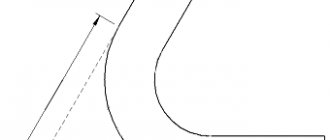
The illustration below shows the operation of a Laval nozzle.
As the gas moves through the nozzle, its absolute temperature T and pressure P decrease, and its speed V increases. The internal energy of the gas is converted into the kinetic energy of its directed motion. The efficiency of this conversion in some cases (for example, in the nozzles of modern rocket engines) can exceed 70%. M – Mach number (speed of sound).
In the tapering, subcritical section of the nozzle, gas movement occurs at subsonic speeds (M gas reaches sonic speed (M = 1). In the expanding, supercritical section, the gas flow moves at supersonic speeds (M > 1).
The narrowing part of the nozzle is called a confuser, and the expanding part is called a diffuser. The diffuser is always longer than the confuser. Sometimes the length of the diffuser exceeds the length of the confuser by 250 times. Lengthening the diffuser helps to increase the speed of gas flow from the nozzle, and, accordingly, the thrust.
© Photo //www.pexels.com, //pixabay.com, //ru.wikipedia.org/wiki/Laval_Nozzle
outflow rate calculation work outflow from a Laval nozzle Laval nozzle principle of operation drawing buy temperature for air with your own hands formulas for water calculator Wikipedia dimensions
Search for technologies
Technologies found 1
Might be interesting:
Intensive gardening
Wedge mills
Plasma disinfection of drinking water and wastewater
Organic fertilizers and production technology
Fish farms and fish farming technology
Graphene battery and its advantages
RLD security system "Redan-125"
Truss trusses with inclined posts
What is this site about?
This site is dedicated to the author's scientific developments in the field of economics and the scientific idea of implementing the Second Industrialization of Russia.
It includes: - the economy of the Second Industrialization of Russia, - the theory, methodology and tools of innovative development - the implementation of the Second Industrialization of Russia, - the organizational mechanism for the implementation of the Second Industrialization of Russia, - a directory of breakthrough technologies.
We do not sell products, technologies, etc. of manufacturers and inventors! You need to contact them directly!
We negotiate with manufacturers and inventors of domestic breakthrough technologies and provide recommendations on their use.
The implementation of the Second Industrialization of Russia is based on a qualitatively new scientific basis (theory, methodology and tools) developed by the authors of the site.
The end result of the Second Industrialization of Russia is an increase in the well-being of every member of society: the ordinary person, the enterprise and the state.