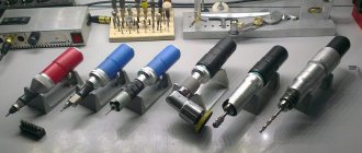
A gas pipeline is an engineering structure, each element and node of which solves an important specific functional task and is responsible for the safety, quality and uninterrupted functioning of the network. A variety of gas fittings and equipment vary in complexity of design, material of manufacture, purpose and type.
Fittings for gas pipelines are a broad class of fixtures and devices that are mounted on gas pipelines, as well as on devices. With their help, switching off/on, changing the direction, quantity, pressure of the gas flow or completely removing gases are carried out. A wide range of these parts are classified, thanks to which you can quite easily understand the issue of classifying gas fittings.
Let's look together at the variety of fittings for gas pipelines and the features of their selection.
Classification of gas fittings.
Based on their purpose, existing types of gas fittings are divided into:
- on shut-off valves - for periodic sealed shutdowns of individual sections of the gas pipeline, equipment and devices;
- safety valves - to prevent the possibility of gas pressure increasing above the established limits;
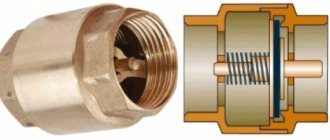
- reverse-acting fittings - to prevent gas movement in the opposite direction;
- emergency and shut-off valves - to automatically stop the flow of gas to the emergency area in case of violation of the specified regime.
When choosing gas equipment and fittings, you must be guided by the current GOST and SP.
Valuable information is contained in the materials of the research center for industrial gas equipment “Gazovik” (NIC PGO “Gazovik”), which collects, analyzes, and verifies the reliability of information about the degree of quality, reliability, competitiveness and safety of industrial gas equipment products.
All fittings used in the gas industry are standardized. According to the accepted symbol, the code for each fitting product consists of four parts. In the first place is a number indicating the type of reinforcement (table below).
What determines the choice of communications?
A special commission is responsible for the project of a new gas pipeline, which determines the route of the pipeline, the method of its construction, and the points for construction of the gas distribution station.
When choosing a laying method, the following criteria are taken into account:
- population of the territory where the gas pipeline is planned to be laid;
- the presence of already extended underground communications on the territory;
- type of soil, type and condition of coatings;
- consumer characteristics - industrial or household;
- the possibilities of various types of resources - natural, technical, material, human resources.
Underground installation is considered preferable, which reduces the risk of accidental damage to pipes and ensures stable temperature conditions. This type is used more often if it is necessary to supply gas to residential areas or separate buildings.
At industrial enterprises, highways are laid overhead - on specially installed supports, along the walls. Open laying is also observed inside buildings.
In rare cases, gas pipes are allowed to be hidden under a concrete floor - in laboratories, public catering places or consumer services. For safety reasons, the gas pipeline is placed in anti-corrosion insulation, filled with cement mortar, and in places where it exits outside it is placed in reliable cases that ensure stability.
Symbols for the type of reinforcement
| Type of fittings | Type designation | Type of fittings | Type designation |
| Pipe valves | 11 | Rotary check valves | 19 |
| Shut-off valves | 14 and 15 | Valves regulating | 25 |
| Lift check valves | 16 | Gate valves | 30,31 |
| Valves safety | 17 | Gates | 32 |
On the second - the symbol of the material from which the valve body is made (table below).
Features of choosing fittings and equipment
When choosing fittings for gas pipelines, you should pay particular attention to the chemical and physical properties of the material from which it is made.
The most popular materials for the manufacture of gas fittings are cast iron and steel. This is due to the requirements for an increased level of strength and reliability. Polymer elements, which are excellent for water pipelines, are not applicable here; in addition, they can be easily damaged.
Steel is the most popular material for the manufacture of gas fittings. Such equipment is affordable and highly durable.
Experts do not recommend using equipment with bronze sealing inserts on gas pipelines. This is due to the fact that LPG contains hydrogen sulfide, which can have a negative effect on bronze and copper alloys.
Symbols for valve body materials
| Housing material | Designation material | Housing material | Designation material |
| Carbon steel | With | Brass and bronze | b |
| Acid-resistant and stainless steel | nz | Viniplast | VP |
| Gray cast iron | h | Alloy steel | PM |
| Malleable cast iron | CC | Aluminum | A |
The third is the serial number of the product. On the fourth - symbol of the material of the sealing rings: b - bronze or brass; nzh - stainless steel; r - rubber; e - ebonite; BT - babbitt; bk - there are no special sealing rings in the body and on the shutter.
For example, the designation of the PbYubk crane is deciphered as follows:
11 - type of fittings (faucet), b - body material (brass), 10 - serial number of the product, bk - type of seal (without rings).
Most types of valves consist of a shut-off or throttling device. These devices are a housing closed with a lid, inside which the shutter moves.
Moving the valve inside the housing relative to its seats changes the area of the hole for gas passage, which is accompanied by a change in hydraulic resistance.
In shut-off devices, the surfaces of the valve and seat that come into contact when parts of the gas pipeline are disconnected are called sealing surfaces. In throttling devices, the valve and seat surfaces that form a controlled passage for gas are called throttling surfaces.
Basic technical requirements for pipeline fittings
The main technical requirements for pipeline fittings include:
- Tightness in relation to the external environment and tightness in the valve.
- Structural strength and ability to withstand loads (constant and short-term pressures, forces and torques) without deformation that disrupts the normal operation of the product.
- Absence of stagnant zones and cavities; ensuring reliable operation after the valve has been in the closed or open position for a long time.
- Maintainability, allowing the replacement of wear parts without cutting out fittings from the pipeline.
- Performance of parts under conditions of frequent starts and stops of equipment; simplicity and ease of maintenance, ensuring a guaranteed number of opening-closing cycles under operating parameters.
There are special requirements for safety valves, the main ones being the following:
- When the maximum permissible pressure is reached, the rotary check valve must open without failure and allow the working medium to pass in the required quantity.
- When activated, the valve must operate stably without vibration.
- The valve should close when the pressure decreases.
- The valve in the closed state at operating pressure must provide the required degree of tightness.
Shut-off
the fittings must have:
- minimal hydraulic resistance;
- necessary tightness in the valve;
- ease of working.
Regulatory
the fittings must:
- provide the necessary throughput characteristics and control accuracy;
- perform, if necessary, the functions of shut-off valves to seal the valve;
- have a flow part that is resistant to erosion wear;
- emit a noise level of no more than 85 dB at a distance of no more than 1 m;
- do not create vibration in the adjacent pipeline.
The materials of valve bodies and covers should be selected based on the strength properties of steels at operating temperatures.
The materials of the sealing surfaces must be resistant to corrosion in water and steam, and resist the erosive effects of the flowing medium, which is especially important for control valves, the flow parts of which operate under conditions of high flow rates of the medium. The materials of steel valve seals must have a high tensile strength (at least 400÷500 MPa) at operating temperatures, sufficiently high hardness (HRC>40) and high resistance to scuffing
The materials of steel valve seals must have high tensile strength (at least 400÷500 MPa) at operating temperatures, sufficiently high hardness (HRC>40) and high resistance to scuffing.
The fittings produced by factories must comply with the standards given in the Rostekhnadzor Rules.
The warranty period for the operation of pipeline fittings is established in accordance with the manufacturer's specifications (but no more than 24 months from the date of putting the products into operation and no more than 36 months from the date of crossing the border of the Russian Federation for export deliveries).
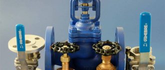
Shut-off valves.
Shut-off valves include various devices designed to hermetically shut off individual sections of a gas pipeline. They must ensure tight shutdown, quick opening and closing, ease of maintenance and low hydraulic resistance.
Gate valves, taps, and valves are used as shut-off valves on gas pipelines.
The most common type of shut-off valves is valves (figure below), in which gas flow or its complete cessation is controlled by changing the position of the valve along the sealing surfaces. This is achieved by rotating the flywheel. The spindle can be retractable or non-retractable. When the flywheel rotates, the non-retractable spindle moves around its axis along with the flywheel. Depending on which direction the flywheel rotates, the threaded gate bushing moves along the threads on the bottom of the spindle down or up and lowers or raises the gate valve accordingly. Rising stem valves move the spindle and associated valve by rotating a threaded bushing mounted in the center of the handwheel.
For gas pipelines with a pressure of up to 0.6 MPa, valves made of gray cast iron are used, and for gas pipelines with a pressure of more than 0.6 MPa, valves are made of steel.
Gate valves can be parallel or wedge. In parallel valves, the sealing surfaces are located parallel, with a spacer wedge between them.
Conclusions useful video on the topic
You can learn how to maintain shut-off valves on a gas pipeline from the following video:
The design features of wedge and hose valves will be discussed in this video:
All gas pipelines are considered high-risk objects, so the choice of gas fittings and equipment should be taken seriously, and, if necessary, consult with specialists. Only high-quality gas shut-off valves can ensure ease of maintenance, speed of repair, and high tightness of pipeline components.
If you have questions about the topic of the article, or can add interesting information to our material, please leave your comments in the block below.
Valves
a - parallel with a retractable spindle: 1 - body; 2- locking discs; 3 - wedge; 4 - spindle; 5 - flywheel; 6 — stuffing box; 7 - sealing surfaces of the body; b - wedge with non-retractable spindle: 1 - wedge; 2- cover; 3 - bushing; 4 - nut; J - flywheel; 6 — oil seal; 7 - collar; 8 - spindle
When closing the valve, the wedge rests on the bottom of the valve and pushes the disks apart, which create the necessary density with their sealing surfaces. In wedge valves, the side surfaces of the valve are not parallel, but oblique. Moreover, these valves can be with a solid shutter or a shutter consisting of two disks. It is advisable to install parallel valves on underground gas pipelines.
However, valves do not always provide a sealed shutdown, since the sealing surfaces and bottom of the valve often become dirty. In addition, when operating valves with the shutter not fully open, the discs wear out and become unusable.
All repaired and newly installed valves must be checked for tightness with kerosene. To do this, the valve should be installed in a horizontal position and kerosene should be poured on top; on the other side, the valve should be painted with chalk. If the valve is tight, there will be no kerosene stains on the valve.
On underground gas pipelines, valves are installed in special wells (figure below) made of precast reinforced concrete or red brick. The well cover must be removable for ease of disassembly during repair work.
Construction of gas wells
a - installation of a valve in a well: 1 - case; 2 - valve; 3 - carpet; 4 — hatch; 5 — lens compensator; 6 - gas pipeline; b - construction of a small-sized well: 1 - outlet; 2 - tap; 3 - gasket; 4 - well wall
The wells have hatches that can be easily opened for inspection and repair work. On the roadway, hatches are installed at the level of the road surface, and on unpaved driveways - 5 cm above ground level with a blind area of 1 m in diameter around the hatches. Where possible, it is recommended to move the valve control under the carpet.
Where gas pipelines cross the walls of the well, cases are installed, which are sealed with bitumen for density. Wells must be waterproof. An effective remedy against the penetration of groundwater is waterproofing the walls of wells. In case of water penetration, special pits are installed in the wells to collect and remove it.
On gas pipelines with a diameter of up to 100 mm, when transporting dried gas, small-sized wells are installed (figure above) with fittings installed in the upper part, which ensures servicing of the fittings from the surface of the ground. In such wells, taps are installed instead of valves.
In forced lubrication valves (figure below), sealing is achieved by introducing a special grease under pressure between the sealing surfaces. The lubricant tucked into the hollow channel of the upper part of the plug is pumped through the channels into the gap between the body and the plug by screwing the bolt. The plug rises slightly upward, increasing the gap and ensuring ease of rotation; the ball valve and brass gasket prevent the grease from being squeezed out and gas from penetrating out.
1.3. Three-way valve.
Designed for connecting gas pipelines where a safety plug and releasing residual pressure from the line are required, as well as for installing a pressure gauge on the gas pipeline.
A three-way valve is a shut-off device with a valve to relieve pressure and quickly shut off the line. The tap has M 24x1.5 threads on all sides for connection to pipelines. After completion of work, gas emissions into the atmosphere are minimal.
The three-way valve can be used as a shut-off device with a valve for high pressure on a gas-air pipeline. To do this, a ¾ pipe thread is cut on both sides and one side is plugged.
The valve body is made of stainless steel 12x18N10t.
Overall dimensions of the locking device, mm
length (with handle) ………………………………….192
width………………………………………………………60
height (with handle) …………………………… 76
Manufacturer: Pipeline Elements Plant JSC, r.p. B. Source
Sverdlovsk region (1.13).
2. Direct flow valves.
2.1. Gate valve type ZM - 65x21 with manual drive.
The valve ZM - 65x21 (Fig. 3.) consists of the following components: body, slotted nut, spindle, bearing cap, running nut, flywheel, thrust ball bearings, stuffing box, gate, seats, disc springs and discharge valve.
The initial tightness of the valve is achieved by creating the required specific pressure on the sealing surfaces of the gate and seats using disc springs. The tightness of the connection between the housing and the lid is ensured by a metal gasket by tightening the slotted nut; adjustment of the alignment of the through holes of the gate and the body is carried out using adjusting nuts screwed into the upper casing.
To make it easier to control the valve, the running nut rests on thrust ball bearings; the threads of the spindle and running nut are moved out of the contact area with the medium, which improves its operating conditions. The spindle is sealed using an oil seal assembly, into which sealing lubricant is injected to increase its reliability.
During the assembly process, the bearing assembly is filled with grease, and during operation, grease is supplied to the assembly through an oiler; There are slots in the upper casing of the valve that allow you to determine the position of the valve (open-closed). The valve has the ability to supply protective lubricant to the body through the discharge valve, which protects it from contamination and corrosion.
The principle of operation of the valve is that when the flywheel rotates, the reciprocating motion through the spindle is transmitted to a single-plate gate, which opens or closes the passage hole of the valve. To avoid erosive and corrosive wear, the valve should not be operated in the half-open position.
Technical specifications:
Conditional bore, mm……………………………65
Working pressure, MPa (kgf/cm2) ………………….21 (210)
Control…………………………………………manual
Macroclimatic region according to GOST 16350-80……moderate and cold
Borehole environment……………………………………. oil, gas, gas condensate, process water, waste water, oil field water, sea water with impurity content up to 0.5% H2S and CO2 up to 0.003 by volume each
Temperature of the well environment, K (0C), no more than ……. 393 (120)
Overall dimensions, mm……………………………350x320x650
Weight, kg;
Assembled ………………………………………. 64
Complete set……………………………………………………… 66
Manufacturer: Baku Oilfield Engineering Plant, Baku (1.9).
Pages: 1 Next Last
Cast iron valve with pressure lubrication
1 - channels; 2 - base of the plug; 3 - bolt; 4 - ball valve; 5 - gasket
In addition to lubricated valves, simple rotary valves are used, which are divided into tension, gland and self-sealing valves. These valves are installed on above-ground and on-site gas pipelines and auxiliary lines (pulse and purge gas pipelines, condensate collector heads, inlets).
In tension taps, mutual compression of the sealing surfaces of the plug and the body is achieved by screwing the tension nut onto the threaded end of the plug, equipped with a washer.
To create tension in the plug, the end of its conical part should not reach the washer by 2-3 mm, and the lower part of the inner surface of the body should have a cylindrical groove. This makes it possible, as the valve plug wears out, to lower it lower, tightening the shank nut, and thereby ensure tightness.
Condensate collectors
a - high pressure; b - low pressure; 1 - casing; 2 - inner tube; 3 - contact; 4 - lock nut; 5 - tap; 6 - carpet; 7 - plug; 8 — reinforced concrete cushion under the carpet; 9 — grounding electrode; 10 — condensate collector body; 11 - gas pipeline; 12 — gasket; 13 - coupling; 14 - riser
Depending on the humidity of the transported gas, condensate collectors can have a larger capacity for wet gas and a smaller capacity for dry gas. Depending on the gas pressure, they are divided into condensate collectors of low, medium and high pressure.
A low-pressure condensate collector is a container equipped with an inch tube, which runs under the carpet and ends with a coupling and plug. Condensate is removed through the tube, the gas pipeline is purged and the gas pressure is measured.
Medium and high pressure condensate collectors are somewhat different in design from low pressure condensate collectors. They have an additional protective tube, as well as a valve on the internal riser. The hole in the upper part of the riser serves to equalize the gas pressure in the riser and the case. If there were no hole, condensate under gas pressure would constantly fill the riser. At low temperatures, condensate may freeze and risers may rupture.
Under the influence of gas pressure, condensate is automatically pumped out. When the tap is closed, the gas acts against the condensate, which falls down under the influence of its mass. When the tap is opened, the resistance stops and the condensate comes to the surface.
Gas pipeline installation
Gas pipeline installation
Installation of a gas pipeline is a very responsible process and access to it is carried out only by installers who have undergone special training.
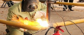
Gas pipelines are laid indoors from steel pipes: seamless, straight-seam welded, spiral-seam, water-gas pipes, etc., the welds of which are equal in strength to the base metal of the pipe. Pipes are usually connected by welding. Threaded and flanged connections are provided only in places where shut-off valves, gas appliances, instrumentation, etc. are installed. Detachable connections of gas pipelines must be accessible for inspection and repair. Connecting parts and gas pipeline parts made of ductile cast iron or mild steel (cast, forged, stamped, bent or welded) are used.
When making bent bends or bent sections of gas pipelines from water and gas pipes during gas pipeline installation, the bending radius should be at least 2.5 DR - for pipes with a diameter of up to 40 mm inclusive and 3.5 DR - for pipes with a diameter of 40-50 mm inclusive. Pipes with a diameter of more than 50 mm are not used for these purposes.
To seal threaded connections, flax strands are used, coated with red lead or lead white, fluoroplastic material (FUM) in the form of tape and cord, as well as other sealants that ensure the tightness of the connections. Gaskets for flange connections are made of paronite. To connect gas pipelines during welding, the type and brand of electrodes, welding wire and fluxes are selected depending on the grade of steel being welded. For manual electric arc welding of steel pipes and products, thickly coated electrodes E42, E46, E50A, E42A and E46A are used. For automatic and semi-automatic submerged arc welding, welding wire of the Sv-08-A grade is used, for pipes made of low-carbon steels and grade Sv-08-GA for pipes of low-alloy steels. When welding pipes in a gaseous carbon dioxide (carbon dioxide) environment, welding wire of the Sv-08G2S grade is used; for gas welding, welding wire of the Sv-08A and Sv-08GA grades is used.
Gas pipelines are equipped with valves, taps, and gate valves designed for gas environments. Rotary valves and gate valves must have 90° rotation limiters, and valves with a non-rising spindle must have opening degree indicators. Valves with diameter up to 80 mm must have a mark indicating the direction of gas passage in the plug. The valve seals are stuffed with asbestos cord impregnated with graphite mixed with mineral oil.
When installing internal gas pipelines, the pipes are connected by welding. Threaded and flange connections are used in places where disconnecting devices, compensators, pressure regulators, instrumentation and other fittings are installed, as well as in places where gas appliances and burners are connected to the gas pipeline. At the points of connection with fittings or fittings, gas pipelines should not have distortions.
Welded and threaded connections of gas pipelines and fittings are not allowed to be embedded in walls or ceilings. Sections of gas pipelines laid in casings should not have butt joints. They must be painted during installation. The distance from the weld to the casing (when the gas pipeline passes through a wall or foundation) is taken to be at least 100 mm.
You watched: Gas pipeline installation
Compensators.
During the operation of gas pipelines, the temperature change can reach several degrees, which causes stresses of several tens of MPa. Therefore, to prevent the destruction of the gas pipeline from temperature influences, it is necessary to ensure its free movement. Devices that ensure the free movement of pipes are compensators - lens, lyre-shaped and U-shaped. On underground gas pipelines, lens compensators are most widespread (figure below).
Lens compensator
1 - pipe; 2 - flange; 3 - shirt; 4 - half lens; 5 - rib; 6 - paw; 7 - nut; 8 - thrust
Lens compensators are made by welding from stamped half-lenses. To reduce hydraulic resistance and prevent clogging inside the compensator, install
a guide pipe welded to the inner surface of the compensator on the gas inlet side. The lower part of the lenses through the holes in the guide pipe is filled with bitumen to prevent the accumulation and freezing of water in them.
When installing the compensator in winter, it is necessary to stretch it a little, and in summer, compress it with tie rods. After installation, the rods must be removed. Compensators, when installed next to valves or other devices, provide the ability to freely dismantle flange fittings and replace gaskets (figure below).
Options for connecting valves, other valve-type devices and gas appliances
When installing a pipeline network, you can use a coupling, pin, flange, welded, fitting, clamp or nipple connection.
Flange is used to solve the problem of connecting a valve or other fitting device to a pipeline or tank provided DN>50 mm. This type of connection can be used over a wide range of pressures and passages, and is one of the most reliable. Its advantages are significant strength and the ability to repeatedly install and dismantle the structure without loss of quality. There are also disadvantages, which include heavy weight and loosening of tightness leading to leakage during long-term operation, which requires correcting the problem during maintenance.
Couplings can connect equipment with DN=<65 mm. The couplings used for connection have internal threads. A hex wrench is required for installation.
The pin type, unlike the coupling type, has an external thread.
Using welding, a permanent connection of high reliability and guaranteed tightness is obtained. Due to the disadvantage manifested in the complexity of replacing and repairing fittings, the method is used less often than others.
In the nipple version, the connection of certain fittings to a tank or pipeline is carried out using a nipple, in the fitting version - a fitting.
In the compression fitting, the pipes are tightened to the pipeline flanges using studs and nuts.
Installation of expansion joints
a - lens with a valve; b - rubber-fabric; 1 - lower casing; 2 - upper casing; 3 - pin; 4 - coupling; 5 - nozzle; 6 — cap; 7 - small carpet; 8 — pillow under the carpet; 9 — reinforced water and gas pipe; 10 — welded flange; 11 - valve; 12, 14 — gaskets; 13 — two-lens compensator
Due to the fact that there is very often water in the wells, the nuts and coupling bolts rust, so working with them becomes difficult, and in some cases, operating personnel leave the coupling bolts on the lens compensators without removing the nuts. The lens compensator ceases to perform its function, so new compensator designs do not provide tie bolts. During repairs, a clamp is used to compress expansion joints.
Due to the fact that the expansion joints are made of thin-walled steel with a thickness of 3-5 mm, they cannot be of equal strength to the pipe. Limited pressure is the main disadvantage of lens compensators. To increase the permissible pressure, expansion joints are made of stronger steel, with more waves, but less height.
There are expansion joints made of bent, usually seamless pipes (U-shaped and lyre-shaped). The main disadvantage of such compensators is their large dimensions. This limits their use on large diameter pipelines. In gas supply practice, bent expansion joints are not widespread and are not used at all as installation expansion joints when installing valves.
Rubber-fabric compensators have great advantages (figure above). They are able to perceive deformations not only in the longitudinal, but also in the transverse directions. This allows them to be used for gas pipelines laid in mining areas and in earthquake-prone areas.
Great Encyclopedia of Oil and Gas
Gas inlets into buildings from the yard line or street network are laid in stairwells or basements. In residential buildings, inputs are arranged separately for each section. When laying pipes through the foundation masonry, measures are taken to protect them from destruction during settlement of the building. The pipe located in the wall is wrapped with resin rope and placed in a case - a pipe of larger diameter.
It is preferable to make gas inlets into houses in the basement. Entering gas pipelines into basements and semi-basements and laying gas pipelines along them (if there are no special technical corridors) is prohibited. It is not allowed to install plugs on basement and intra-house gas pipelines.
The gas inlet can be made not only into the stairwell, but also into the non-residential basement of the building.
Gas inlets of gas tanks are passed through special chambers in which shut-off valves, gas protection, valves for manual discharge and control valves for releasing gas into the atmosphere when gas tanks overflow are placed, as well as heating system control units and non-flammable gas pipeline valves for purging gas tanks and gas inlets.
Recessed steel gas inlets installed under buildings must be enclosed in a gas-tight cartridge. The latter must be located in an accessible and commonly used part of the building. Where the cartridge ends, the annular space between the cartridge and the inlet pipe must be sealed to prevent gas leakage.
Low-pressure gas inlets of short length (up to 25 m) are allowed to be put into operation without testing them for density under air pressure. In this case, the density of the gas pipeline (input) is checked in an unfilled trench under operating gas pressure by coating the connections with soap emulsion or another equivalent method.
| Yard gas pipeline diagram. /, 2, 3, 4, 5, 6, 7 and 8 – gas risers. |
A gas inlet is a gas pipeline running from the distribution (street) network to the riser of the intra-house gas network.
| Yard gas pipeline diagram. 1, 2, h, 4, 5, v, 7 8 – gas risers. |
A gas inlet is a gas pipeline that runs from the distribution (street) network to the riser of the indoor gas network.
| Yard gas pipeline diagram. |
A gas inlet is a gas pipeline running from the distribution (street) network to the riser of the indoor gas network.
Gas inlets and risers are purged sequentially, starting with the most distant inlet and riser.
Since there are gas inlets into the building on each of the two staircases, and the gas pipeline layout in the left half of the building completely coincides with the distribution in its right half, the gas pipeline diagram can only be drawn up for half of the building.
Pages: 1 2 3 4 5