LEDs, which appeared on the radio electronics market relatively recently, have already firmly taken a leading position in relation to other light sources. They are the most economical in terms of energy consumption, more compact and convenient to use and have less heat generation.
And yet, no matter how high-tech the LED is, an increase in temperature during its operation cannot be avoided. In addition, when heated, such an LED element, due to its design features, begins to lose its luminous flux.
Of course, if it is a regular DIP LED with two contact legs, external cooling is quite enough for it. But if we take more powerful elements, then it’s worth thinking about a cooling radiator for LEDs, which would help remove heat from the light source.
If you pay attention to similar cooling devices in stores, you can understand how high their cost is. What to do then?
It remains to figure out whether it is possible to make a radiator for a specific LED or group of LEDs yourself, how to do it, and how difficult it is. Now we will try to resolve this issue.
Why is it needed?
Along with other semiconductor devices, the LED is not an ideal element with 100% efficiency. Most of the energy it consumes is dissipated into heat. The exact efficiency value depends on the type of emitting diode and its manufacturing technology. The efficiency of low-current LEDs is 10-15%, and for modern white ones with a power of more than 1 W, its value reaches 30%, which means that the remaining 70% is spent as heat.
Whatever the LED, for stable and long-term operation it requires a constant removal of thermal energy from the crystal, that is, a radiator. In low-current LEDs, the radiator function is performed by the leads (anode and cathode). For example, in SMD 2835 the anode lead takes up almost half of the bottom of the element. In high-power LEDs, the absolute value of power dissipation is several orders of magnitude greater. Therefore, they cannot function normally without an additional heat sink. Constant overheating of the light-emitting crystal significantly reduces the service life of the semiconductor device and contributes to a gradual loss of brightness with a shift in the operating wavelength.
Structurally, all radiators can be divided into three large groups: plate, rod and ribbed. In all cases, the base can be in the shape of a circle, square or rectangle. The thickness of the base is of fundamental importance when choosing, since it is this area that is responsible for receiving and uniformly distributing heat over the entire surface of the radiator.
The form factor of the radiator is influenced by the future operating mode:
- with natural ventilation;
- with forced ventilation.
A cooling radiator for LEDs that will be used without a fan must have a distance between fins of at least 4 mm. Otherwise, natural convection will not be enough to successfully remove heat. A striking example is the cooling systems of computer processors, where, due to a powerful fan, the distance between the fins is reduced to 1 mm.
When designing LED lamps, great importance is given to their appearance, which has a huge impact on the shape of the heat sink. For example, the thermal energy dissipation system of an LED lamp should not go beyond the standard pear-shaped shape. This fact forces developers to resort to various tricks: using printed circuit boards with an aluminum base, connecting them to the radiator housing using hot-melt adhesive.
Introduction
LED lamps have firmly entered our lives; they can be found in almost every home, in enterprises, in various institutions, and on the street. They help save energy, are reliable, have a long service life, as well as a whole set of technical characteristics that give these lamps an advantage over lighting devices of previous generations.
LED fixtures produce less heat than most fixtures with other light sources. But, nevertheless, during operation of the device, natural heating of the LEDs occurs. If the heat dissipation is poor, the temperature of the LEDs may be higher than permissible for their normal operation. If the elevated temperature of the LEDs remains constant, after some time the phosphor will degrade and the color temperature of the diodes will change. The luminous flux will also decrease, while energy consumption will remain the same, that is, energy efficiency will decrease, and the service life of the lamp will noticeably decrease.
Radiator materials
Currently, cooling of high-power LEDs is carried out mainly using aluminum radiators. This choice is due to the lightness, low cost, flexibility in processing and good heat-conducting properties of this metal. Installing a copper radiator for an LED is justified in a luminaire where size is of paramount importance, since copper dissipates heat twice as well as aluminum. Let's consider the properties of materials that are most often used for cooling high-power LEDs in more detail.
Aluminum
The thermal conductivity coefficient of aluminum is in the range of 202–236 W/m*K and depends on the purity of the alloy. According to this indicator, it is 2.5 times higher than iron and brass. In addition, aluminum lends itself to various types of mechanical processing. To increase heat dissipation properties, the aluminum radiator is anodized (coated black).
Copper
The thermal conductivity of copper is 401 W/m*K, second only to silver among other metals. Nevertheless, copper radiators are much less common than aluminum ones, which is due to the presence of a number of disadvantages:
- high cost of copper;
- complex mechanical processing;
- large mass.
The use of a copper cooling structure leads to an increase in the cost of the lamp, which is unacceptable in conditions of fierce competition.
Ceramic
A new solution in creating highly efficient heat sinks has become aluminum nitride ceramics, the thermal conductivity of which is 170–230 W/m*K. This material is characterized by low roughness and high dielectric properties.
Using thermoplastic
Despite the fact that the properties of thermally conductive plastics (3–40 W/m*K) are worse than those of aluminum, their main advantages are low cost and lightness. Many LED lamp manufacturers use thermoplastic to make the housing. However, thermoplastic loses competition to metal radiators in the design of LED lamps with a power of more than 10 W.
Types and applications
While maintaining the same principle of placing LED crystals on a heat-conducting substrate, LED matrices differ significantly in the number of crystals on one base and the methods of connecting them to each other.
The number of crystals on one substrate determines the final power of the matrix, which can reach hundreds of watts per product. Powerful matrix light sources have proven themselves in floodlights and street lighting fixtures.
Another feature of the internal connections of crystals with external pins is the possibility of using LED matrix structures in information displays and in graphic or character screens. Such LED matrices find their application in control and measuring equipment and all kinds of advertising installations.
Cooling features of high-power LEDs
As mentioned earlier, effective heat removal from the LED can be achieved by organizing passive or active cooling. It is advisable to install LEDs with a power consumption of up to 10 W on aluminum (copper) radiators, since their weight and size indicators will have acceptable values.
The use of passive cooling for LED arrays with a power of 50 W or more becomes difficult; The dimensions of the radiator will be tens of centimeters, and the weight will increase to 200-500 grams. In this case, it is worth considering using a compact radiator together with a small fan. This tandem will reduce the weight and size of the cooling system, but will create additional difficulties. The fan must be provided with the appropriate supply voltage, and care must also be taken to protect the LED lamp in the event of a cooler failure.
There is another way to cool powerful LED matrices. It consists of using a ready-made SynJet module, which looks like a cooler for a medium-performance video card. The SynJet module features high performance, a thermal resistance of no more than 2 °C/W and a weight of up to 150 g. Its exact dimensions and weight depend on the specific model. Disadvantages include the need for a power source and high cost. As a result, it turns out that a 50 W LED matrix must be mounted either on a bulky but cheap radiator, or on a small radiator with a fan, power supply and protection system.
Whatever the heatsink, it can provide good, but not the best, thermal contact with the LED substrate. To reduce thermal resistance, heat-conducting paste is applied to the contacted surface. The effectiveness of its impact has been proven by its widespread use in cooling systems for computer processors. High-quality thermal paste is resistant to hardening and has low viscosity. When applied to a radiator (substrate), one thin, even layer over the entire contact area is sufficient. After pressing and fixing, the layer thickness will be about 0.1 mm.
How to connect a HPS lamp
Here is a compact shield assembled with your own hands, according to the connection diagram.
You can, of course, assemble all this in the overall body of the lamp, if the dimensions allow.
It is very important, before assembling such a circuit yourself and using any components, using a conventional multimeter in the maximum resistance measurement mode, check the insulation of the inductor and capacitor. Is there a hole in the body? Is there a hole in the body?
Is there a hole in the body?
To supply and disconnect 220V power, use a two-pole input circuit breaker.
For one lamp with a power of up to 400W, a machine with a nominal value of 5-6A is quite suitable. In addition to on-off switching operations, it will also play the role of a protective device.
A circuit breaker is mounted at the very beginning of the circuit. Do not forget to also ground the entire panel body.
Two neutral wires come out of the machine. According to the diagram, one of them is connected directly to the lamp, and the second one is connected to the corresponding terminal labeled “N” on the starter.
Keep in mind that the choke must be installed only in the open phase wire going to the lamp, and not in the neutral wire.
Otherwise, you can accidentally burn the product if during operation the neutral wire after the ballast choke accidentally shorts out. Next, turn off the phase. Mount one wire from the machine to the incoming contact of the throttle.
And connect the wire from the output contact to terminal “B” (Balast) of the ballast.
After that, connect the middle terminal Lp (Lampa) to the light bulb socket.
IZU switching circuits
Let's consider the parallel launch scheme of the IZU. In such a circuit, the lamp current does not pass directly through the IZU, which virtually eliminates any power loss. The circuit of the ignition device for such inclusion is quite simple, the devices themselves are inexpensive, easy to operate and quite reliable. However, high-frequency pulses generated by the ignition device in such a circuit affect, in addition to the lamp, also the choke, which necessitates the use of chokes with increased insulation, resistant to voltages of 2–5 kV.
Since standard chokes for metal halide and sodium lamps do not support this voltage value, the parallel IZU switching circuit is used only with lamps whose ignition voltage is less than 2 kV. First of all, such lamps include high-power metal halide lamps (from 2000 to 3500 W).
Calculation of radiator area
There are two methods for calculating a radiator for an LED:
- design, the essence of which is to determine the geometric dimensions of the structure at a given temperature;
- calibration, which involves acting in the reverse order, that is, with known radiator parameters, you can calculate the maximum amount of heat that it can effectively dissipate.
The use of one or another option depends on the available initial data. In any case, accurate calculation is a complex mathematical problem with many parameters. In addition to the ability to use reference literature, take the necessary data from graphs and substitute them into the appropriate formulas, you should take into account the configuration of the radiator rods or fins, their orientation, as well as the influence of external factors. It is also worth considering the quality of the LEDs themselves. Often, in Chinese-made LEDs, the actual characteristics differ from the declared ones.
Exact calculation
Before moving on to formulas and calculations, it is necessary to become familiar with the basic terms in the field of thermal energy distribution. Thermal conduction is the process of transferring thermal energy from a more heated physical body to a less heated one. Thermal conductivity is expressed quantitatively as a coefficient that shows how much heat a material can transfer through a unit area when the temperature changes by 1°K. In LED lamps, all parts involved in energy exchange must have high thermal conductivity. In particular, this concerns the transfer of energy from the crystal to the case, and then to the radiator and air.
Convection is also a process of heat transfer that occurs due to the movement of molecules of liquids and gases. In relation to LED lamps, it is customary to consider the exchange of energy between the radiator and the air. This can be natural convection, occurring due to the natural movement of air flow, or forced, organized by installing a fan.
At the beginning of the article it was stated that about 70% of the power consumed by an LED is consumed as heat. To calculate a heatsink for LEDs, you need to know the exact amount of energy dissipated. To do this we use the formula:
PT – power released in the form of heat, W; k is a coefficient that takes into account the percentage of energy converted into heat. This value for high-power LEDs is taken equal to 0.7-0.8; UPR – forward voltage drop across the LED when the rated current flows, V; IPR – rated current, A.
It's time to count the number of obstacles located in the path of the heat flow from the crystal to the air. Each obstacle represents a thermal resistance, indicated by the symbol (Rθ, degrees/W). For clarity, the entire cooling system is presented in the form of an equivalent circuit of series-parallel connection of thermal resistances
Rθjc – thermal resistance pn-junction-case; Rθcs – thermal resistance of case-surfase radiator; Rθsa – thermal resistance radiator-air (surfase radiator-air).
If you plan to install an LED on a printed circuit board or use thermal paste, then you also need to take into account their thermal resistance. In practice, the value of Rθsa can be determined in two ways.
Rθja – resistance pn-junction-air; Tj – maximum pn-junction temperature (reference parameter), °C; Ta – air temperature near the radiator, °C.
Find from the graph “the dependence of the maximum thermal resistance on the forward current.”
Based on the known Rθsa, a standard radiator is selected. In this case, the rated value of thermal resistance should be slightly less than the calculated value.
Approximate formula
Many radio amateurs are accustomed to using radiators left over from old electronic equipment in their homemade products. At the same time, they do not want to delve into complex calculations and buy expensive new imported products. As a rule, they are only interested in one question: “How much power can the existing aluminum LED radiator dissipate?”
We suggest using a simple empirical formula that allows you to obtain an acceptable calculation result: Rθsa=50/√S, where S is the surface area of the radiator in cm 2.
Substituting into this formula the known value of the total area of the heat sink, taking into account the surface of the ribs (rods) and side faces, we obtain its thermal resistance.
We find the permissible power dissipation from the formula: Pt=(Tj-Ta)/Rθja.
The above calculation does not take into account many nuances that affect the quality of operation of the entire cooling system (directionality of the radiator, temperature characteristics of the LED, etc.). Therefore, it is recommended to multiply the obtained result by a safety factor of 0.7.
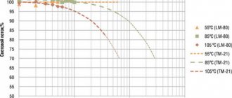
Temperature dependencies
As the temperature of the LED crystal increases, along with a decrease in the luminous flux, the forward voltage and, as a result, power consumption decrease.
The drop in power partially compensates for the decrease in luminous flux, and efficiency drops slowly with temperature - this must be taken into account. Example 1
Graph of efficiency versus temperature of LEDs released more than three years ago, LXM8-PW27 and LXM8-PW30, shown in the Philips Lumileds DS63 documentation (Fig. 1). Efficiency increases up to +25…+50 °C and does not decrease significantly up to a temperature of +75 °C.
Rice. 1. Graph of LED efficiency versus chip temperature from Philips Lumileds DS63 technical documentation
Example 2
The technical documentation for the Osram OSLON Square LED (LCW_CQAR.PC) provides detailed graphs of the dependence of forward voltage and luminous flux on temperature. If you multiply the values from these two graphs, you get the dependence of relative efficiency on temperature (Fig. 2). Efficiency remains virtually unchanged up to a crystal temperature of +85 °C.
Rice. 2. Dependence of the relative efficiency of the Osram OSLON Square LED (LCW_CQAR.PC) on the crystal temperature
Example 3
Cree, in its technical documentation for LEDs, provides graphs of the dependence of luminous flux on temperature, approximating complex dependences by linear ones, and gives the average coefficient of temperature dependence of voltage. This does not determine the temperature up to which efficiency does not decrease, but it does provide an estimate of "on average" how much efficiency will decrease as the temperature increases. With an increase in chip temperature by 10 ° C, the luminous flux of various Cree LEDs decreases by 2–2.5%, forward voltage by 20–30 mV, power consumption by 0.7–1.0%, efficiency by 1.0 -1.5%.
For further assessments, we will use the average values of these ranges: with an increase in temperature by 10 °C, the luminous flux decreases by 2.25%, forward voltage by 25 mV, power consumption by 0.85%, and efficiency by 1.25%.
DIY LED radiator
It’s not difficult to make an aluminum radiator for 1, 3 or 10 W LEDs with your own hands. First, let's look at a simple design, the manufacture of which will take about half an hour and a round plate 1-3 mm thick. Along the circumference, cuts are made to the center every 5 mm, and the resulting sectors are slightly bent so that the finished structure resembles an impeller. To attach the radiator to the body, holes are made in several sectors. It's a little more difficult to make a homemade heatsink for a 10-watt LED. To do this you need 1 meter of aluminum strip 20 mm wide and 2 mm thick. First, the strip is cut with a hacksaw into 8 equal parts, which are then stacked, drilled through and tightened with a bolt and nut. One of the side faces is polished for mounting the LED matrix. Using a chisel, the strips are bent in different directions. Holes are drilled in the places where the LED module is attached. Hot melt adhesive is applied to the sanded surface, a matrix is applied on top, fixing it with self-tapping screws.
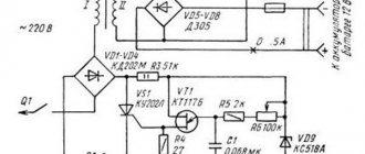
Details
The circuit operates under a mains voltage of 220 V, so capacitors with an operating voltage of at least 600 V, paper type KGB or film K73-17, are used. The thermal dissipation power of the resistor is 0.25÷0.5 W.
The minimum permissible reverse voltage of the diodes is 400 V. D226B, KD105B-G or their imported analogues are suitable. The diodes are replaced by a bridge assembly KTs402-407. The zener diode is selected with a maximum current at an operating voltage of 12 V.
Parallel connection of capacitors increases the total capacitance, summing up the ratings of all elements. The desired value is selected by combining several elements.
Which fan controller should I buy?
Choosing the best PC fan controller just got a lot easier (I hope). The clear winner on the list is the mighty Corsair Commander Pro, and that's down to its functionality as well as its excellent software. While the Commander Pro doesn't have a touchscreen display like the Thermaltake Commander, it certainly gets the job done and has two separate channels for RGB lighting.
For a more budget-friendly, simpler fan controller, we chose the DeepCool FH-10 - it's the way to go, as it's available at an unbeatable price. For a lower profile setup with fewer fans, the Noctua NA-FC1 is a solid option.
Of course, what you choose depends entirely on your preference and build, but rest assured that no matter which fan controller you choose from this list, you won't be disappointed.
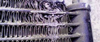
Causes of breakdowns
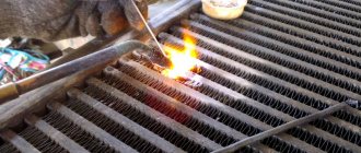
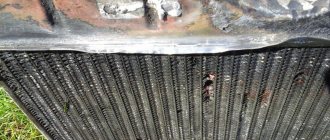
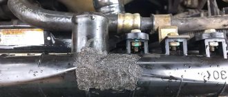
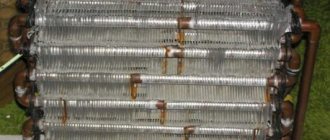
Usually, repair of car radiators is necessary either due to banal human negligence (failure to comply with maintenance rules) or due to an accident (accident, road traffic accident). In the event of an accident, as a rule, the front part of the car suffers, and the radiator, being a relatively fragile structure, receives excessive loads. However, if the cooling radiator leaked after you forgot to drain the water in winter, it means that during the frost the ice did its terrible work. Or, for example, an unscrupulous car enthusiast filled the cooling system not with distilled water, but with tap or well water. In this case, when heated, residues of salts and other slags settled on the inner walls of the pipelines and honeycombs of the radiator, which ultimately reduced the efficiency of the cooling system and led to breakdown.
True, if you know how to use an industrial soldering iron, you can try to repair the cooling radiator yourself. However, quality control of soldered seams, as well as general tightness, must be ensured at the highest level.
What to Consider Before Buying a Fan Controller
There are a few things to consider before purchasing a new fan controller or fan hub. Some fan controllers have different characteristics, number of channels and, of course, software.
Fan controller aesthetics
Most of the time the fan controller may be hidden. Sometimes these fan controllers are designed so that they can sit inside your system without looking like birds made a nest in your case.
Pin support
Different fan controllers support different types of fan pins; this will usually be three or four pin.
3-pin models are more complex than the older 2-pin models, with two pins for negative and positive current and a third pin for RPM control.
The 4-pin pin does all of the above, but with the addition of an additional fourth pin, which is dedicated to pulse width modulation (PWM), acting as a switch that constantly turns on and off, adjusting the amount of power to the fan.
Channels
Number of channels may vary from controller to controller
It's important to make sure you get a controller with the right number of channels. The Noctua in this list only supports up to three channels, so always keep an eye on that!
Control
If any of these devices have controls, they are often very basic with limited customization options. Software like iCUE for Corsair Commander is excellent and gives you real flexibility with configurations. Other control options include touch screens such as the Thermaltake controller.
What is self-cooling and how is it used?
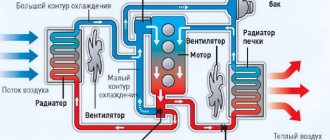
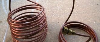
The operating principle of the autonomous cooling system is based on the fact that the coolant liquid is supplied to the refrigerator from a small 5-liter container using a pump. As a result, alcohol vapor condenses in the refrigerator. The heated water from the refrigerator flows to the lower radiator pipe, where it is cooled by a fan. Then the cooled liquid again enters the container from the upper radiator pipe. This installation is shown in the diagram below:
1 - Distillation cube. 2 - Refrigerator. 3 — Radiator with fan. 4 - Canister with water. 5 - Water pump.
Such a system has the following advantages:
- Minimum fluid consumption. It is enough to fill the system with water once. The liquid needs to be changed only after 1-2 distillations.
- The water in the system is under pressure, so its level in the hoses will not change sharply.
- The moonshine unit can be installed regardless of the proximity of the water source - in the basement, garage, loggia, etc.
- There is no problem associated with liquid disposal.
- In the absence of water supply, an autonomous type system will be the optimal solution.
- In winter, an autonomous moonshine still can be placed in fresh air without using a fan.
The only disadvantages include noisy operation, the need for electricity and the cost of purchasing all the necessary parts.
Second calculation method
There is another simple formula, which was obtained through experiments.
S = [22 – (M x 1.5)] x W, where S is the heat exchanger area, W is the supplied power (W), and M is the unused power of the LED.
For the finned type of radiator made of aluminum, you can use the data provided by engineers from Taiwan. The data is not accurate, as it is indicated in ranges with a large run-up rate. In addition, the definition is suitable for the climatic conditions of Taiwan. They can be taken as a basis only when making preliminary calculations.