Correctly calculated overlap of reinforcement during tying affects the final quality of the structure. The reliability of this method is difficult to challenge, however, there are certain nuances in the work process, if not observed, the result of the connection may turn out to be fragile and short-lived. This can also affect the rate at which the concrete hardens, causing the base to become very soft.
Why is it necessary to comply with reinforcement overlap standards when knitting?
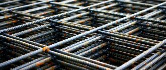
When pouring the foundation of a house or when erecting any other concrete structure (column or monolithic block), the issue of strength and durability of the structure remains pressing. Subject to compliance with all building codes, an additional metal frame will greatly strengthen the structure and make it durable, and the base unaffected by natural conditions and time.
If the rules are not followed, the foundation of the house may soon collapse, which will lead not only to the loss of a large amount of materials, but also to human casualties. This is due to the fact that incorrectly calculated overlap of reinforcement leads to non-hardening of concrete in some places, which leads to weakening of the entire structure as a whole. To build a strong and reliable frame, several methods are used, including knitting, for which it is necessary to use an overlap.
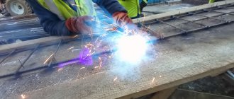
Connecting reinforcement bars by welding
For private construction, welding overlapping reinforcement bars is expensive, since it is recommended to use welded class A400C or A500C reinforcement. Using rods without the “C” symbol in the marking will result in a loss of strength and corrosion resistance. Reinforcement grades A400C - A500C should be welded with electrodes Ø 4-5 mm.
| Reinforcement class | Weld length in rod Ø |
| A 400 C | Ø 8 |
| A 500 C | Ø 10 |
| At 500 C | Ø 10 |
Thus, according to the table, the length of the weld when knitting rods of the B400C brand should be 10 Ø of the rod. When using 12mm rods the seam will be 120mm long.
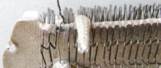
Overlapping weld joint
The amount of overlap when connecting reinforcement according to SNIP
The Sanitary Standards and Rules of 2003 (abbreviated SNiP) describe all types of fittings connections that currently exist. Overlapping joints are created without the use of welding machines, in this they differ from mechanical (for which couplings and special equipment are used) and welded (for which a welding machine is respectively required). There are three types of overlap joints:
- Rods with hooks and claws (bends) at the ends.
- Rods with a straight end (with welding or installation at the intersection of reinforcement).
- Rods with straight ends (profile).
The Sanitary Standards and Rules of 2003 recommend overlapping reinforcement with a cross-section of up to 40 mm. In turn, the world analogue of building codes, namely ACI 318-05, states the maximum permissible value of the cross-section of the rods is 36 mm. This is due to the lack of evidence base for the reliability of connections of larger diameter, since no tests have been carried out. Also during knitting, it is worth leaving a certain free space around the overlap.
It must be taken into account that the minimum distance that must be left for reserve, both horizontally and vertically, is 25 mm. However, if the cross-section of the reinforcement itself is more than 25 mm, then the margin must be calculated according to the diameter step. The largest distance between elements is 8 sections of the rod. But when using wire in knitting, the distance is reduced to 4 sections.
It is not recommended to use tying in areas of greatest pressure, since the joint is not designed for such loads, but only for fastening the reinforcement and maintaining them as a single structure.
Types of connections between reinforcing elements
To construct a frame frame, different types of reinforcement connections are used. There are three main ways to join two reinforcing bars:
The overlapping reinforcement is joined as follows:
- using auxiliary parts: loops, paws, hooks. For A1-class fittings, only hooks and loops are used;
- overlap of reinforcing profile rods with straight ends;
- overlap of reinforcement with straight ends and transverse connection.
Mechanical joining of reinforcement (MSA) is classified as follows:
- pressed anchoring of reinforcement: the ends of the rods are connected inside a steel cylinder, which is crimped with a hydraulic press. As a result, the steel cuts between the ribs of the profile reinforcement
- threaded: made using a connecting cylinder with a cylindrical/conical thread cut inside. The corresponding thread is made at the ends of the connecting reinforcement bars;
- bolted: the reinforcement is connected by bolts screwed into the reinforcement body through the coupling wall;
- screw joining is made using a coupling, inside of which a thread identical to the profile of the reinforcement is cut and secured with locknuts.
Welded connection: The reinforcement is anchored using welding.
Reinforcement overlap under different conditions
The joint locations of the reinforcement and the location of the lattice should be determined by the designer, not the builders. Since the overall picture of the project, as well as knowledge of the load in different places, is known only to him. Otherwise, the design may be damaged.
For example, when reinforcing a column, several fundamentally important steps should be followed:
- The outlet must be bent to a slightly longer length than the cross-section of the reinforcement (for a diameter of 16mm it is 20mm).
- It is necessary to bend the reinforcement without heating, but with the help of special means that can provide the required bending radius.
- The bend radius must be indicated in the project and emphasis should be placed on it, since builders are unlikely to do this without instructions.
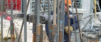
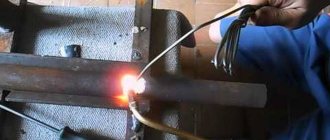
Fixation of reinforcing bars by electric welding
Butt jointing of reinforcing bars by welding is carried out only with reinforcement of classes A500C and A400C, because these grades relate to the materials being welded. The most common grade A400 cannot be joined by welding, since after heating it loses its anti-corrosion property and becomes less durable.
As Russian GOST 10922 and its replacement 14098 state, electric arc welding can be used for joining overlapping reinforcement with a diameter of less than 25 mm.
Attention! The length of the weld seam depends on the type of diameter of the reinforcing bar. For welding, electrodes with a cross section of 4 - 5 mm are used.
Consumption rates for reinforcement for overlap
The required length of reinforcement bars varies according to several criteria:
- For compression reinforcement, the required length will be as follows. So, for fittings with a diameter of 6 mm - length 20-22cm; 8mm - length 20-29cm; 10mm - length 25-36cm; 12mm - length 30-43cm; 14mm - length 35-50cm.
- For tensile reinforcement, the required overlap length of the bars must be greater. For example, for a diameter of 6 mm - length 20-29cm; 8mm - length 27-38cm; 10mm - length 33-48cm; 12mm - length 40-57cm; 14mm - length 46-67cm.
The higher the strength class of concrete, the shorter the length of the overlap rods should be. The only exceptions are 20, 28 and 32 mm fittings. With concrete strength class B35, the length of the rods should be 655, 920 and 1050 mm, respectively.
Do you comply with the norms for overlap of reinforcement when tying?
Yes
No
Basic requirements for making overlap joints
When performing overlapping reinforcement joints, there are rules defined by construction documentation. They define the following parameters:
- The size of the rod lining;
- Features of the location of the connections themselves in the body of the concreted structure;
- The location of adjacent bypasses relative to each other.
Taking these rules into account allows you to create reliable reinforced concrete structures and increase the period of their trouble-free operation. Now about everything in more detail.
Where to place reinforcement overlap joints when knitting
SNiP does not allow the location of overlapping reinforcement ties in areas of the greatest load on them. It is not recommended to place joints in places where steel rods experience maximum stress. It is best to place all connecting rod connections in unloaded areas of reinforced concrete, where the structure is not under stress. When pouring a strip foundation, the bypass ends of the reinforcement are placed in places with minimal torque and minimal bending moment.
If it is not technologically possible to fulfill these conditions, the length of the overlap of the reinforcing rods is taken at the rate of 90 diameters of the joined rods.
What is the amount of overlap of reinforcement when knitting?
Since the overlap of the reinforcement is determined by the technical documentation, the length of the joint connections is clearly indicated there. In this case, the values can vary not only from the diameter of the rods used, but also from such indicators as:
- Nature of the load;
- Concrete grade;
- Reinforcing steel class;
- Connection points;
- Purpose of reinforced concrete products (horizontal slabs, beams or vertical columns, pylons and monolithic walls).
Splicing reinforcing bars when performing overlaps
In general, the length of the overlap of reinforcement bars during tying is determined by the influence of the forces arising in the rods, the perceived adhesion forces with concrete acting along the entire length of the joint, and the forces that provide resistance in the anchoring of the reinforcing bars.
The fundamental criterion when determining the length of the reinforcement overlap during tying is its diameter.
For the convenience of calculating the overlap of reinforcing bars when knitting the load-bearing frame of a monolithic foundation, we suggest using a table with the indicated diameter values and their overlap. Almost all values are reduced to 30 times the diameter of the rods used.
| The amount of reinforcement inlet in diameters | ||
| Diameter of reinforcing steel A400, mm | Overlap amount | |
| in diameters | in mm | |
| 10 | 30 | 300 mm |
| 12 | 31,6 | 380 mm |
| 16 | 30 | 480 mm |
| 18 | 32,2 | 580 mm |
| 22 | 30,9 | 680 mm |
| 25 | 30,4 | 760 mm |
| 28 | 30,7 | 860 mm |
| 32 | 30 | 960 mm |
| 36 | 30,3 | 1090 mm |
Depending on the loads and purpose of the reinforced concrete products, the length of the lap joints of the steel rods changes upward:
| Inlet of reinforcement depending on the purpose of reinforced concrete products | ||
| Type of load | Purpose of concrete products | |
| Horizontal use, in diameters | Vertical use, in diameters | |
| In compressed concrete | 33.8 ᴓ | 48.3 ᴓ |
| In stretched concrete | 47.3 ᴓ | 67.6 ᴓ |
Depending on the grade of concrete and the nature of the load used for pouring the monolithic foundation strip and other reinforced concrete elements, the minimum recommended values for the bypass of reinforcement during the binding process will be as follows:
| For compressed concrete | ||||
| Diameter of reinforcing steel A400 used in compressed concrete, mm | Length of overlap of reinforcing bars for concrete grades (concrete strength class), in mm | |||
| M250 (B20) | M350 (B25) | M400 (B30) | M450 (B35) | |
| 10 | 355 | 305 | 280 | 250 |
| 12 | 430 | 365 | 335 | 295 |
| 16 | 570 | 490 | 445 | 395 |
| 18 | 640 | 550 | 500 | 445 |
| 22 | 785 | 670 | 560 | 545 |
| 25 | 890 | 765 | 695 | 615 |
| 28 | 995 | 855 | 780 | 690 |
| 32 | 1140 | 975 | 890 | 790 |
| 36 | 1420 | 1220 | 1155 | 985 |
| For stretched concrete | ||||
| Diameter of reinforcing steel A400 used in tensile concrete, mm | Length of overlap of reinforcing bars for concrete grades (concrete strength class), in mm | |||
| M250 (B20) | M350 (B25) | M400 (B30) | M450 (B35) | |
| 10 | 475 | 410 | 370 | 330 |
| 12 | 570 | 490 | 445 | 395 |
| 16 | 760 | 650 | 595 | 525 |
| 18 | 855 | 730 | 745 | 590 |
| 22 | 1045 | 895 | 895 | 275 |
| 25 | 1185 | 1015 | 930 | 820 |
| 28 | 1325 | 1140 | 1040 | 920 |
| 32 | 1515 | 1300 | 1185 | 1050 |
| 36 | 1895 | 1625 | 1485 | 1315 |
How to position reinforcement bypasses relative to each other
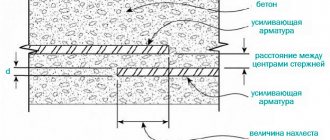
To increase the strength of the foundation's load-bearing frame, it is very important to correctly position the reinforcement overlaps relative to each other in both planes of the concrete body. SNiP and ACI recommend spacing connections so that there are no more than 50% bypasses in one section. In this case, the spacing distance, as defined in regulatory documents, must be at least 130% of the length of the connecting connection of the rods.
Mutual arrangement of reinforcement bypasses in the concrete body
If the centers of overlap of the knitted reinforcement are within the specified value, then it is considered that the connection of the rods is located in the same section.
According to ACI 318-05 standards, the relative position of the connecting connections must be at a distance of at least 61 centimeters. If the distance is not maintained, then the likelihood of deformation of the concrete monolithic base from the loads exerted on it during the construction of the building and its subsequent operation increases.
Mechanical connection method
Reinforcement diagram where stiffeners are used.
Number “1” indicates reinforced mesh, number “2” indicates vertical rods. If the rods are joined using a mechanical connection, then a hydraulic press will be a mandatory requirement. As for materials, this process requires rods, as well as threaded and pressed couplings.
Mechanical connection technology is one of the simplest; installation proceeds as follows:
- A coupling must be placed on the rod.
- Next, crimping occurs using a press.
- For the next reinforcement bar, the work pattern is repeated.
As you can see, the process goes quite quickly. Thick-walled pipes can be used as an alternative to couplings. Couplings with a central partition are also used. A mechanical connection is used for rods of different diameters, since a hydraulic press is involved in the work. The main advantage of this method for private construction is that you can handle the installation yourself. You don’t have to hire workers, since even a novice builder can operate the press
Basic provisions of SNiP
Construction rules and regulations prohibit fastening rods in application areas and places where the structure is subject to maximum load. Installation of rods can be carried out both with and without binding wire. As for the reinforcement, the cross-section of which is 25-30 millimeters, here experts recommend using a coupling or pressed connection.
Between the rods that will overlap, there must be a distance of at least 25 millimeters or more, then the concrete can fill the entire frame of the future structure. The overlap can also be made using a knitting wire, in which case the distance between the rods can be equal to 0. The largest distance between the rods must be chosen so that it does not exceed 4 diameters of the reinforcing elements. As for the distance between pairs of joints, with this type of fastening it should be at least 30 millimeters, but also at least two diameters.
How to properly knit reinforcement for a monolithic slab - general information
Tables of cross-sectional area and reinforcement range
A slab foundation is an important element of a building, consisting of the following components:
- sand-crushed stone cushion damping soil reaction;
- branded concrete made according to a standard recipe;
- power grid, for the manufacture of which you can take reinforcing bars.
The reliability and durability of the foundation is determined by the quality of the slab, the upper part of which has to bear the weight of the structure, and the lower part has to compensate for the reaction of the soil.
For a monolithic slab, tying reinforcement is much simpler than for a strip foundation
A power grid made of steel reinforcement located inside a concrete mass performs a number of serious tasks:
- provides a margin of safety for the foundation;
- prevents destruction of the slab and the formation of cracks;
- absorbs compressive loads and bending moments.
A solid slab is a floating foundation that ensures the integrity of the structure during soil movements. The design ensures the stability of buildings on problematic soils, provided that the reinforcement grid elements are correctly knitted and high-quality concrete is used. When performing knitting work, one should be guided by the requirements of the state standard, as well as building codes and regulations governing the specifics of knitting.
Let us dwell in more detail on the requirements for the reinforcement grid and the nuances of knitting:
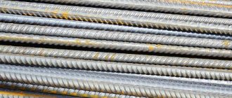
- for the manufacture of gratings, ribbed rods are used, which provide increased adhesion of the elements;
- form two tiers of power grids connected to each other by vertical rods with a concrete thickness of 15 cm or more;
- perform single-layer reinforcement with a grid with square cells ranging in size from 20x20 cm to 40x40 cm with a slab thickness of less than 15 cm;
- For rigid connection of reinforcement frame elements, annealed wire intended for knitting reinforcement is used.
When answering the question about the features of correct tying of reinforcing elements intended to strengthen a monolithic foundation, experts recommend using the following tying methods:
Knitting reinforcement begins with the purchase of metal, the amount of which must first be calculated with the minimum possible margin
- manual, providing reliable fixation at minimal cost. To connect the rods, it is necessary to make significant efforts when performing work with wire cutters or using a crochet hook;
- semi-automatic, allowing you to perform an increased volume of work through the use of a special reversing device. The rotation of the hook occurs as a result of the reciprocating movement of the body;
- automatic, designed for accelerated tying of reinforcement at large industrial facilities. The use of a special knitting gun or a screwdriver with an attachment ensures increased work efficiency.
The choice of knitting tool is carried out individually depending on the volume of work performed:
- for a one-time assembly of a reinforcement grid, a crochet hook or reversible device is suitable;
- When producing reinforcement cages on an industrial scale, an automatic gun should be used.
When performing work, a number of rules must be observed:
- to ensure a strong connection of the rods, correctly use a binding wire with a cross-sectional diameter of 0.8-1.4 mm;
- the connection of individual rods should be made with wire in the areas of their mutual intersection;
- when twisting the wire, force should be applied to ensure rigid fixation of the reinforcing bars
The reinforcement itself is laid and knitted along the footing, which is then connected into a common frame
Scope of application of the reinforcing frame
Reinforcing mesh provides a multiple increase in the strength of any structure that involves its use. The key tasks during construction are considered to be reinforcing the foundation and giving greater strength to the walls - creating a kind of wall frame. which ensures long-term operation of the entire structure.
- Reinforcement of quickly destructible road surfaces.
- For reinforcement during masonry work.
- To strengthen the foundation.
- To improve performance and strengthen thermal insulation.
- For leveling and maximizing the strengthening of the original floor covering.
- For strengthening walls when working with plaster.
- It is also used in the production of partitions in both private houses and apartments.
Technical features of weldless joint
It is necessary to space adjacent connections apart. Moreover, in such a way as to achieve simultaneous connection in one section of up to 50% (no more) of the reinforcing elements. The design section, which we will determine in order to determine the value of the joining reinforcements, is understood as the area of 130% of the total overlap parameter (measured along the bars).
Here it is necessary to understand that when designing, the joints of the rods are considered as lying in the same section, provided that the centers are located exactly in the specified zone. The shortest distance between joints according to SNiP is 610 mm. According to ACI 318–05 and sanitary standards, it is recommended that untied (free) connections of rods be made in structures without prestressing.
This advice is quite logical, because the concrete mixture with such a connection will flood the rods from all sides. And this is a guarantee of ultra-reliable fixation of each rod, which cannot be achieved when pouring an incomplete circle of reinforcement and an adjacent rod tied with binding wire. In addition, the overlap in length cannot be less than 25 cm.
Another important provision of the Sannorm is that in the 1st design section the connection can have no more than 50% of steel rods in the foundation strip. In addition, it is possible to join welded mesh and individual reinforcing elements using the described option without the necessary separation. However, such an assumption will only be valid when using reinforcement for structural reinforcement.
An overlap of 30 cm or more is possible provided that the reinforcement is functioning in compression. In many foreign countries, in construction documentation, the overlap was set at a level of 40 diameters of the connecting reinforcing elements. In the CIS countries, this value is equal to 50 diameters (A400 fittings).
Also, the value of the recommended overlap depends on the grade of concrete for pouring the foundation. For example, for the M300 mixture it has 35 diameters, M250 - 40, M200 - 50. But for reinforcing bars A-II and A-I, the overlap is always selected based on 40 diameters. But it should be borne in mind that all this will be true for the indicators in the calculation. In practice, real (not minimum) overlap values are usually several times larger.
SNiP for welding reinforcement allows you to understand the technology of carrying out and work and determines safety standards.
What a home handyman needs to know:
- when working with the device, exposed areas of the body and eyes are subject to protection (shields, masks, helmets with light filters, gloves, uniforms);
- to prevent poisoning from dust, fumes and harmful gases, a special respirator is used;
- Welding equipment must be checked for serviceability and grounding, otherwise you may receive an electric shock.
- the equipment creates an electromagnetic field, this is not dangerous if you follow the work technology;
- When operating outdoors, the device must be under a canopy;
- Transportation regulations must be observed.
Types of anchored reinforcement
Consumption rate of tying wire per 1 ton of reinforcement
The classification of reinforcement is quite extensive, metal rods are selected according to several parameters, and the calculation takes into account maximum nuances. Depending on the operating conditions, the reinforcement can be prestressed or non-prestressed. Depending on the location in the reinforced concrete structure, it can be transverse and longitudinal.
Transverse reinforcement prevents inclined cracks from appearing and prevents shear stresses that appear near concrete supports. Longitudinal reinforcement prevents vertical cracks from propagating in certain longitudinal zones where tensile stresses are concentrated in concrete.
Classification of fittings by purpose:
- Distribution – secures the frame by welding in the position specified in the project
- Working - perceives forces that appear under the influence of the gravity of the structure, external loads, etc.
- Assembly – increases the rigidity of the reinforcement frame during assembly and transportation to the site
- Anchor – designed for attaching various types of embedded parts to a structure
Depending on the diameter of the rod and the purpose of the metal parts, the reinforcement can be rope, rod, wire (cross-section up to 10 millimeters), etc.
To create a high-quality reinforcement frame, only special profile rods are used. The stronger the concrete and the reinforcement suitable for the operating conditions, the more reliable and durable the reinforced concrete structure will be.