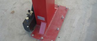
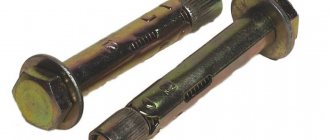
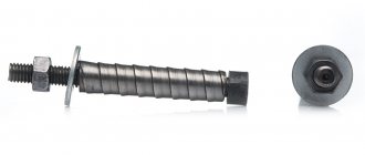
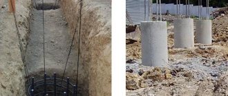
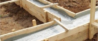
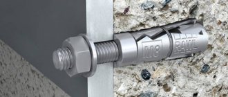
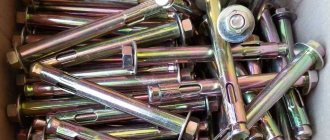
The reliability of building structures is greatly facilitated by the anchor bolts used when connecting the foundation base to the walls of the buildings being built. Fasteners significantly increase the stability of buildings and can also be used for the construction of complex structures. The products are distinguished by their size, high strength, as well as a fixation system that allows for reliable engagement with the building material - the task will be completed subject to a competent approach to implementation, which consists in the correct selection of products and compliance with installation technology.
What are anchor bolts for foundation work made of?
The tasks performed by fastening elements involve high loads, and therefore they are made from high-strength materials. Most often, steel and its variations are used in production, which makes it possible to increase the product’s resistance to temperature changes and other external influences. The manufacturing technology also involves heat treatment of the anchor bolts, which ensures the reliability of the connection of the fastening elements to the structure.
Foundation bolts are characterized by high strength, durability and reliability, while different types of fastening systems are suitable for different tasks. Thus, fasteners can be used in foundation structures of different scales; accordingly, the length of the products will differ (the depth of embedment can be from 15 cm to 5 m), as well as their diameter. The anchor is attached to the support of the structure or wall elements, and in industrial workshops heavy equipment is mounted using bolts.
Depending on the design features, production and permissible loads that the product can withstand, the price also varies. When purchasing foundation anchors, it is important to make sure that the product is made in accordance with the requirements of GOST and has passed the necessary testing (before releasing the product to the market, it is tested under conditions of appropriate loads and potential external influences). The technical features, area and conditions of use of bolts can be determined using special markings that are applied to the product in accordance with GOST.
Unloading the machine from transport.
Let's start with delivering the equipment to the territory where it is intended to be used. Unloading equipment requires sufficient qualifications of personnel involved in unloading work. Lifting mechanisms (forklifts, cranes, slings, traverses) must have a higher lifting capacity compared to the weight of the equipment. The use of mechanisms whose load capacity is lower than the weight of the equipment can lead to emergency situations, damage to equipment, and harm to the health of personnel. For this reason, lifting mechanisms are always chosen, so to speak, “with a reserve.” Speaking about the crane, it should be noted that there is a dependence of the crane’s lifting capacity on the boom reach.
Figure 1: Lifting strap
Rice. 2 Loading the machine with a crane
If slings are used, then textile ones. Here we are not saying that preference should be given to textile slings, but rather that they should be used exclusively.
Figure 3: Textile lifting slings
Transporting a machine from the unloading site to the installation site sometimes causes significant difficulties. It is necessary to consider whether the floor is level, whether there are devices for moving the machine around the workshop, etc. For such transportation the following are used:
- Winch
- Cart
- Forklift
Figure 4: Winch for transporting the machine
Fig 5: Cart for transporting the machine
Figure 6: Forklift for transporting the machine
Main types
As we found out, various variations of anchors are used for connection, differing in design and selected according to the expected load. Taking into account the characteristics of fasteners, several main types are distinguished.
Let's look at the different types of anchor bolts and what are the features of each type.
Curved
The products are made of high-strength steel; in the lower part of the anchor there is a bend that follows the shape of the hook. Regarding foundation work, in this case the rods are mounted in wells or reinforced concrete foundations, after which they are filled with concrete.
With anchor plate
Foundation fasteners of this type are also installed by immersion into the well before concreting. The design difference of this type of product is the presence of a metal plate welded or attached by means of a threaded connection with a hole in the middle, through which a pin is passed. In accordance with the modification, the rods vary in diameter and shape, and washers also come in different sizes and shapes.
Composite
As the name suggests, the products are made of two main parts connected by means of a coupling. Installation of the fastening system involves immersing the lower part in concrete (the lower pin and coupling are mounted before concreting) and screwing the upper part of the bolt, which remains outside, into the coupling, then the top is welded after installation of the equipment.
Removable
Fasteners of this type are installed in two stages. The fastener includes a lower cage (the anchor reinforcement can be composite, cast or welded), installed in the foundation and a threaded stud, which is installed after pouring the concrete. Such fasteners are convenient when repair or replacement of equipment is required during its service life.
Direct
A direct-type product is mounted into hardened concrete, for which a hole is first made in the foundation base, after which the bolt is installed. For reliable fixation, epoxy or silicone glue is used; an alternative option is to use cement mortar. This type of product is used for fastening to a solid base that eliminates deformation loads.
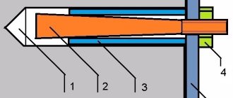
With tapered end
Fasteners are mounted into a finished foundation; this type is often used for fastening pieces of furniture or plumbing fixtures. Reliable fixation is due to an expanding collet that wedges and holds the structure.
Table 1. Basic dimensions for anchor bolts.
Taking into account the tasks and operating conditions, a distinction is made between structural and design fastenings. The former are usually used for fastening massive equipment to ensure stability of the pressure of the weight of the object. The latter take the loads that arise during the operation of the structure or equipment. The length and diameter of the thread are assigned depending on the length of the studs and the diameter of their thread.
If we are talking about large massive structures, care should be taken to ensure accurate markings and correct installation of fasteners.
Table 2. Theoretical mass of product type 1 (length is taken in accordance with GOST 6636, all dimensions in this and the following tables are indicated in millimeters).
Table 3. Theoretical weight of Type 2 bolt.
Table 4. Theoretical mass of product type 5.
Table 5, part 1. Theoretical mass of a type 6 bolt.
Table 5, part 2.
Metal inventory conductor
| Additional Description | Conductor for installation of reinforced concrete columns, conductor for reinforced concrete columns, inverted metal conductor, GOST Inventory metal conductor 400x400mm, conductor for installation of columns diagram, conductor for reinforced concrete columns, Photo of inventory conductor, Inventory conductor, Conductor for installation of columns 400x400mm, Conductor for installation of columns 400x400 , Metal conductor, Conductor for assembling columns, Conductor for assembling reinforced concrete columns, Single conductor for columns of multi-storey buildings, conductor in construction price, Installation devices and tools. Load-handling devices. 8 (4822) 493-659 +7(919) 067 72 75 website: www.td-sgo.ru E-mail: |
Moscow
Provider
CONSTRUCTION EQUIPMENT PLANT (price list)
Telephone
+7
Similar offers
Other offers – Lifting equipment for construction – Moscow
Add to cart Compareyondi.ru
Calculation of anchor bolts
To determine the holding capacity before installation work, you will need to make a calculation using the formula. The main provisions for the calculation of anchor bolts are set out in SP 43.13330.2012. The set of rules contains the necessary information, including requirements and factors that are important to consider when making calculations.
According to the nature of the impact, the loads applied to the bolts can be static (in this case, the pressure is constant and is taken according to the calculated values from the tables) and dynamic (varies depending on the direction of the applied force).
The steel grade of bolts at ambient temperatures down to -65°C is assigned according to table (6):
In this case, you can use in production another grade of steel with quality characteristics not lower than those of the steels included in the table.
The calculated tensile strength of metal products Rba is taken from table (7):
For group installation
The load (P) per bolt is calculated for the most loaded element. The calculation is performed using the formula P = -N / n + M y1 / Σyt², where:
N—design force;
M—calculated bending moment;
y1 — distance from the axis of rotation to the most distant hardware;
n is the number of bolts;
yt is the distance from the axis of rotation to the first hardware, taking into account pressed and tensioned fasteners.
When determining the forces, the rotation axis can be taken to pass through the center of gravity of the equipment support area. Similar expressions are also used to calculate the load for through metal columns and vertical steel products of solid section.
Determining the pre-tension value
The fasteners are tightened manually using appropriate devices to a certain degree of tightening (F). The values for various types of loads should be taken as follows:
- for static F=0.75 P;
- for dynamic F= 1.1 P.
*P – design load acting on the anchor.
The cross-sectional area of the rod is calculated using the formula Asa= ko P/ Rba.
Coefficient ko for dynamics = 1.35, for static loads = 1.05. In the case of removable products with anchor plates, ko for dynamics = 1.15.
The thread cross-section of the bolts should be tested in advance for endurance under dynamic influence; the value is determined by the formula Asa = 1.8 χ µ to P / α Rba, where:
χ is the load factor (see the table and is selected depending on the design of the fastening element);
µ — scaling factor (selected from the table);
α is an indicator of the number of load cycles;
Rba—metal tensile strength;
ko - coefficient according to the table.
Table 8. Embedment depth, distance between axes, tightening factor.
* The embedment depth for rods with a diameter of less than 16 mm is indicated in brackets.
**Values in parentheses are for static loads.
Table 9.
Table 10.
Removing the machine from the shipping pallet
All associated components and mechanisms of the machine are removed from the shipping pallet, such as: coolant tank, chip conveyor, transformer, etc.
Figure 7, 8: Inkor LLC specialists unload and remove the machine from the shipping pallet
Next, the machine is detached from the pallet, the slings are secured at points according to the slinging diagram.
Fig. 9: Transporting the machine without a pallet
How to install
Before directly installing anchor bolts into the foundation, you will need to carry out preparations, making sure that the products are standardized according to GOST 24379.1-80, and also pay attention to such a moment as the length of the product. The depth of embedment in the base will depend on this factor, so it is important to ensure that the length does not exceed the height of the building. Failure to comply with this requirement may affect the reliability of the fastening; for example, a situation is possible when the anchor is not fixed in concrete, but ends up in such a not very reliable material as soil.
The installation method may vary depending on the type of product and tasks. Thus, it is practiced to install anchors in wet concrete, before pouring the foundation or after the base surface has hardened. The most common practice is installation in concrete mortar before it hardens. The method of installation into a finished foundation involves drilling a hole for fasteners and is applicable when using spacer and straight bolts.
Installation rules
In order to complete the task correctly and, as a result, obtain a reliable fastening, you should adhere to certain installation rules:
- The correct choice of mounting location requires preliminary familiarization with the building plan. Thus, foundation fasteners are placed only under the walls of the planned building structure. They are not installed in the locations of the doorways of the building, so this point should be clarified in advance.
- After pouring the concrete composition, the fastening element is immersed in it. During the process, it is important to control the depth of contact (it should not exceed the height of the foundation). If the bolt is immersed in a concrete mass that has not yet hardened, the middle of the base is selected.
- An important role during installation is played by the distance between fasteners. It is easy to calculate - the parameter should be equal to two embedment depths.
- After deepening into the wet concrete mixture to the required depth, you need to line up the bolts exactly vertically, and then allow the solution to harden.
- When the concrete has completely hardened, you need to make a block of anchors, for which the parts protruding above the base are fastened with wooden boards or metal plates (the holes made in advance are positioned with the same spacing as the bolts in the base).
Let's take a closer look at some important points.
Gap from bolt to foundation cut
The distance from the edge of the foundation to the axis of the anchor bolt should be as follows:
- 100 mm. for rods with a diameter of up to 30 mm;
- 150 mm. for hardware with a diameter of 48 mm;
- 200 mm. for fasteners larger than 48 mm. in diameter.
When installing paired fasteners, a single anchor plate is used with a gap between the holes according to the calculation.
If the anchoring depth has been increased by 5 diameters, it is permissible to reduce the distance between the anchors by 2 diameters. If there is sheer reinforcement along the edge at the installation site, the gap from the middle of the rod to the cut of the foundation base can be reduced by another 1 diameter.
Anchoring depth
The immersion depth of the foundation bolts largely determines the reliability of the anchoring, and it directly depends on the length of the fasteners themselves. When the height of the base assumes that the fasteners will be completely screwed in, the holes are drilled to the design size, and after installation they are patched with a cement-sand mixture. If the base does not allow the entire anchor to be immersed, it is replaced with a bolt with a bend and a cone-shaped spacer collet.
If necessary, according to the design of using an element three times smaller than the installed fasteners, the product is buried in the concrete to the required depth, and the hardware works with the absolute design resistance. The depth can be reduced in proportion to the force acting on the fastener.
Instructions for installing anchor bolts in the foundation
The process consists of several steps:
- Preparatory work includes, among other things, studying the features of foundation fasteners that are supposed to be used in the work. The products are marked, so that from the markings you can immediately understand what type of anchor is in front of you and what loads the object is designed for.
- When the search for suitable fasteners is completed, it is necessary to designate the locations of future fastenings, taking into account the installation rules (we do not place elements under doorways).
- We carefully check the distance between the anchors (the value should be twice the insertion depth).
- If we are talking about installation in wet concrete, the work is carried out before it hardens, and it is important to ensure that the anchor pins remain in a strictly vertical position, since subsequently, seemingly insignificant tilts can cast doubt on the reliability of the entire structure.
- Finally, the anchors need to be fastened, for which metal plates or wooden boards are used.
If the fastening is installed in hardened concrete, the fastening points should be marked in advance and the step with which they will line up in the structure should be calculated. Then the surface is drilled, and cement mortar or glue is poured into the resulting holes, after which fasteners are inserted. After the material hardens, blocks are also formed from fasteners.
In order to increase reliability, adhesive-based fasteners can be used, which is convenient when securing the structure in case of asymmetry. For regular vibrations affecting the foundation, it is recommended to use spacer fasteners. Anchors with a tapered end cope well with static influences, but are not suitable for installation where there is a risk of vibration.
Thus, fasteners can be installed both in raw concrete (or poured after installation) and in ready-made concrete. If the process of installing anchor bolts into the foundation is strictly followed, no problems will arise during operation in the future, and the fastening elements will properly perform their task, withstanding significant loads.
Transporting the machine to the installation site
Next, the equipment must be moved, so to speak, to a permanent location. This is usually done in the following way: after removing the machine from the shipping pallet (if this is not done at the direct installation site), it is placed on transport carts and transported to the installation site (on the foundation).
For such transportation, it is important that the floor is level and there is a sufficiently large space (if there are turns).
Separate foundations for columns
For the design and construction of individual foundations, most often, regardless of the type of soil on which they are planned to be located, prefabricated or monolithic foundations are selected. The base is a slab or several slabs with a further stepped structure placed on it. In particularly critical areas, the base area is increased and additionally reinforced with a welded grid of reinforcement. In buildings where separate foundations for columns are planned to be placed in the center of the building to ensure large loads, the area of the base is increased, on an additionally poured monolithic platform.
Calculation of foundations for columns
The starting data for calculating the foundation for one column of a building are:
- the mass of the column itself;
- floor mass;
- mass of wall materials;
- the mass of building structures supported by columns.
The calculation of the pressure that acts on one support is carried out using the calculation of the support area of the column itself. So, with a support size of 50*50 cm, the required area will be 2500 square meters. cm. Next, all the masses of the building are summed up and the result is divided by the area of one support.
To calculate the number of columns themselves, data is required on the properties of the soil, the depth of groundwater, their saturation, while, as practice shows, the number of supports is calculated with a margin of at least 50% of the safety margin for each of the columns. If a smaller result is obtained, as a rule, the number of support points is increased.
Foundation structures for reinforced concrete columns
Monolithic and prefabricated bases for columns include a special form in their design into which a reinforced concrete column is installed. In fact, this is a reinforced concrete form, which in construction is called a “glass”.
Glass type foundation
The foundations themselves for reinforced concrete columns can be presented in two main design options:
- in monolithic design;
- prefabricated structures.
The basis of this design is a rectangular slab on which other smaller slabs are located, thus forming a pyramid in the form of steps with a glass crowning it at the top for support. In a monolithic design, the entire base is one piece, but a prefabricated structure is something like a children's pyramid - at the bottom is the largest slab, and then smaller slabs.
Monolithic foundation for columns
Monolithic bases, poured into one monolithic structure, have the edges of the steps at an angle of 90 degrees. Such foundations are mainly equipped directly at the construction site of the structure. For pouring, the axes of future columns are marked at the bottom of the pit in a pre-equipped and prepared place. For each base, formwork is constructed or a removable formwork structure is assembled, the use of which greatly simplifies the work, since it does not require additional costs to verify the correct installation.
For formwork, according to technological maps, the position is set both vertically and horizontally. The last stage of inspection before pouring concrete into a monolithic base is to check for correct placement along the mounting axes. After installing the formwork of the lower tiers, the column support (glass) is checked and installed.
When pouring the base under a complex shape of a reinforced concrete column, the frame is reinforced with a metal mesh or a welded reinforcement frame. For installation on light soils, difficult soils, where increased strength under the foundation is required, it is possible to install an additional platform or install a pile foundation that provides greater strength.
