This metal detector, despite the small number of parts and ease of manufacture, is quite sensitive. It can detect large metal objects, such as a heating radiator, at a distance of up to 60 cm, while small ones, for example, a coin with a diameter of 25 mm, can be detected at a distance of 15 cm.
The operating principle of the device is based on changing the frequency in the measuring generator under the influence of nearby metals and isolating the difference frequency (beats) between the measuring and reference generators.
Since this frequency is in the audio range, it can be heard through headphones.
DIY pulse metal detector
Pirat - stands for: PI - means pulse metal detector, and RAT - author’s website: “radioscot”.
This metal detector has gained fame as a simple and inexpensive device; there are a small number of available parts that are not in short supply; with proper assembly and serviceable parts, the device works immediately, with virtually no settings. If we compare it with a simple metal detector circuit based on frequency beats, then here the depth of metal detection is an order of magnitude better.
There is no discrimination in this type of metal detector; non-ferrous and ferrous metals react almost identically. But with certain skills, you can understand what target is under the sensor.
The assembly and configuration of this metal detector is much simpler than the previously considered pulse metal detector “VINTIK-PI” .
Characteristics of the PIRATE metal detector
- Supply voltage: 9 – 12 volts .
- Current consumption: 30-40 mA .
- Coin detection depth (25mm): 20cm .
- Large metal detection depth: 150 cm .
Of course, the performance largely depends on the parts used, coil diameter, build quality, etc.
Diagram of the metal detector "PIRAT"
There are many different options for PIRATE metal detector circuits and modifications to them.
Option: generator with transistors, receiver with K157UD2
Option: generator on NE555, receiver on K157UD2
Option: generator on NE555, and receiver on TL072
with generator frequency adjustment:
Option: generator on K561LA7/LE5, receiver on K157UD2
Printed circuit board of the PIRATE metal detector
There are also many different options for PP, below are a few options.
Option: generator on NE555, receiver on K157UD2
Option: generator with transistors, receiver with K157UD2
Option: generator on NE555, receiver on TL072
Description of the scheme
The metal detector circuit consists of two main units: transmitting and receiving .
The transmitting unit consists of a pulse generator on the KR1006VI1 microcircuit (foreign analogue of NE555) and a powerful switch on the KP505A field-effect transistor (foreign analogue of IRF740, IRF840).
You can install a reverse bipolar transistor with a K-E voltage of at least 200V. It can be taken from an energy-saving lamp or a mobile phone charger.
To drive a powerful switch, a BC557 transistor is used.
The receiving unit is assembled on the K157UD2 microcircuit (you can assemble a foreign MS TL072), there are back-to-back limiting diodes at the input of the receiver, at the input of the second stage of the receiver there is a filter that cuts out the required part of the pulses, at the output of the second stage there is a transistor BC547, connected to its collector circuit speaker 8-50 Ohm. In place of T3, you can use almost any NPN structure transistor.
List of parts for the PIRATE metal detector
All these radio components were used in old Soviet technology. You can also order them in online stores.
The speaker can be taken from a Chinese portable radio with a resistance of 8 - 50 Ohms. Also, for setting, you need two potentiometers for 10 kOhm and 100 kOhm. The metal detector is powered from 9 - 12 V. Sensitivity and operation are better from 12V. For this purpose, it is better to use batteries used in laptops.
Installation
We recommend soldering the metal detector circuit using pure rosin or an alcohol-rosin solution. Before you begin assembling the entire structure, we recommend checking the integrity of the parts with a multimeter, since radioelements may be defective. After soldering, be sure to thoroughly rinse the board with alcohol (vodka) using a toothbrush.
Metal detector coil
First option
The coil is wound on a mandrel of about 200 mm, it contains 25-30 turns of wire PEV, PEL, PETV... F-0.4 - 0.7. A pan of this size is suitable as a setting.
It is better to wind the number of turns at 30 and then reduce it during the tuning process, achieving maximum sensitivity.
To do this, we bring the coin to the coil and check with how many turns the coin will be “caught” from the greatest distance.
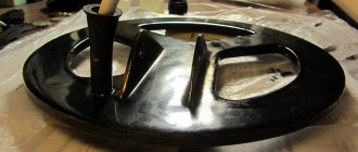
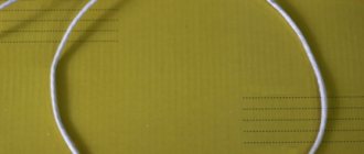
In order for the spool to have good strength and be attached to the barbell, it can be wound, for example, on an embroidery hoop. See photo below.
Second option (basket type coil)
With its help, it is possible to obtain greater detection depth, especially for small metals. The design features of sensors of this type make it possible to obtain a sensitivity up to 20% greater than a conventional sensor.
The coil is wound on a 180 - 200 mm mandrel and contains 4 turns of twisted pair wire for a computer (without foil!) . There are 8 wires in the cable.
4 turns * for 8 wires = we get 32 turns. The inductance of this coil is 330 µH and the resistance is 2 Ohms.
For greater sensitivity, you can wind one turn and get 3 turns of twisted pair 3 ( 3 turns * for 8 wires = we get 24 turns.) , but then you need to adjust the metal detector receiver circuit. Please note that the current consumption will increase.
When we wind the coil: thread the free long end of the cable into the formed loop, wrapping the second turn of the cable around the first. For one turn of the coil, you need to thread the free end of the cable through the coil 4-5 times.
When winding the coil, make sure that the cable is laid, strictly repeating the period of winding the previous turns.
We strip the ends of the wires from insulation, twist them, solder them and put insulating tubes on the connections. The wires of the two ends are connected to form a complete coil. You can connect in any way, one of the options in the table below:
| Wire color of one end | Action | Wire color of the other end |
| connect to the board -> | GREEN | |
| GREEN | WHITE-GREEN | |
| WHITE-GREEN | BLUE | |
| BLUE | WHITE-BLUE | |
| WHITE-BLUE | ORANGE | |
| ORANGE | WHITE-ORANGE | |
| WHITE-ORANGE | BROWN | |
| BROWN | WHITE-BROWN | |
| WHITE-BROWN |
The reel frame must NOT contain metal! The coil itself in this type of metal detector is also NOT wrapped in foil!
The wire connecting the coil and the board must be thick - ordinary electric copper stranded type PVA, PUNGP... 2 x 2.5 mm² or 2 x 1.5 mm², and it is also not advisable to use connections and connectors. In a pulse, the current reaches large values and all of the above affects the sensitivity of the device.
We wrap the coil tightly with electrical tape and solder the connecting wire.
The rod can be made from 4-5 m of PVC water pipe and a couple of jumpers to make the rod more convenient.
At the end of the rod that you will hold, you can install a convenient hand rest made of plastic sewer pipe. Then we install the board in any box of suitable size and attach it to a rod.
The design should not contain any foreign metal elements, as this will greatly distort the electromagnetic field of the device.
Setting up a metal detector
A properly assembled device requires virtually no adjustment. When setting up, you will probably have to select a resistor (R12) in series with the variable (R13) so that clicks in the speaker appear when its motor is in the middle position.
If you have an oscilloscope, you can check the duration of the control pulse and the frequency of the generator at the T2 gate. The optimal pulse option is 130-150 μs, frequency 120-150 Hz.
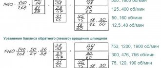
R1 in the generator is responsible for the generation frequency. R2 - for the duration of the control pulse. Voltages at the op-amp terminals (without the presence of metal in the sensor area):
- vyv. 2-6.5v
- vyv. 3-6.5v
- vyv. 5-5.5v
- vyv. 6-3.5v
- vyv. 9-0.7v
- vyv. 13-6.2v
For more detailed settings, as well as when repairing a metal detector, it is advisable to have an oscilloscope. Oscillograms at various points in the circuit are shown in the pictures below.
| 3 leg time.div 10μs volt.div 05v without metal. | 3rd leg - with metal |
| 13 leg-2ms-2v without metal | 13 leg-2ms-2v with metal |
| 13 leg-100mks-2v without metal | 13 leg-100mks-2v with metal |
| 5 leg-1ms-2v without metal | 5 leg-1ms-2v with metal |
| 7 leg-1ms-5v without metal | 7 leg-1ms-5v with metal |
| 7 leg-100mks-5v with metal | legs 2.6 and power—2ms-100mv without metal |
| -1ms - no metal | -1ms- with metal. |
When turning it on, wait 15-20 seconds, after which we use the SENSITIVITY regulator to find a position at which clicks are heard in the speaker - this will be the maximum sensitivity.
Refinement of the metal detector "PIRAT"
Two signal generator circuits
- In order to ensure that there are not clicks in the dynamics, but a “beeping”, a generator circuit is assembled for this purpose in front of the ULF.
Assembling and setting up the device
When the sensor and control unit are ready, you need to connect them into a finished metal detector. For this you will need a barbell. It can be made from PVC pipes and adapters, which are bent to the desired size and shape by heating. You can also use a regular wooden pole, crutch or telescopic fishing rod. Which materials to choose depends on your preferences - consider weight, flexibility and length. For convenience, you can build a handle and an armrest, as well as make the bar collapsible (Fig. 12).
Next, we attach the sensor with ready-made ears to the rod. Use plastic fasteners, reliable glue or plumbing adapters. We fix the control unit in the same way.
To configure, connect the battery and sensor. Since metal detectors are sensitive devices, for proper setup it is necessary to remove all metal objects around. We turn it on and see one of two options:
If after turning on there is perfect silence or a barely audible squeak, then there are two options:
a) Generators operate at the same frequency. Such cases are rare, but they do happen. Try turning the soft R7 and rough R8 adjustment knobs. If the silence changes to a loud tonal sound, then the circuit works. We return the controls to their initial position and try using the smooth control R7 to achieve the best results, for example, complete absence of sound;
b) Circuit malfunction. We carefully recheck the entire circuit and radio components.
If there is a hum or high tone after turning on
, then we try to reduce it by rotating the coarse adjustment knob R8, and having achieved a better result, we adjust R7. If the metal detector does not respond to the rotation of the controls, then the frequency of the reference oscillator is too different from the frequency of the search circuit. In this case, we try to catch the desired frequency by changing capacitor C6 and resistor R6.
An oscilloscope can greatly simplify the entire setup. The essence of the setting is to achieve the same or similar frequency of pins 5 and 6 on the microcontroller. The frequency can be adjusted using the methods described above.
If you have mastered the assembly of this device, you can safely try to assemble a more complex metal detector using three microcircuits or a microcontroller.
DIY metal detector PIRAT
The “Pirate” metal detector circuit is very popular and understandable even to a novice radio amateur.
The Pirate metal detector has quite good characteristics, despite the simplicity of the circuit and the availability of parts.
It can be assembled easily, in an evening, requires virtually no settings or firmware, and starts working immediately after assembly! Below I will present detailed instructions for assembling the Pirate metal detector!
Technical characteristics of MD Pirate:
Current consumption 30-40 mA Supply voltage 9-14 volts No discrimination, reacts to all metals Sensitivity coin 25 millimeters - 20 cm Large metal objects - 150 cm
Nutrition:
To operate the Pirate metal detector, a voltage of 9-14 volts is required.
You can use regular batteries or AA batteries or two batteries connected in parallel, but I would advise spending a little money and buying a battery for an uninterruptible power supply; it can easily be mounted on the metal detector rod and the charge will last for a long time. You can also use a battery from a screwdriver, by the way, at first, that’s what I used!
Coil:
The search coil for the Pirate metal detector is also easy to make. Wound on a 190 mm frame. and contains 25 turns of 0.5 mm PEV wire.
The spool can be wound on an embroidery hoop; by the way, this method is quite common.
Personally, I take an ordinary saucepan, wind a coil on it and tie it all together with electrical tape, then I make a frame out of thin plywood and secure it to it. Here, as they say, to each his own, as it suits.
Required parts:
Download parts list
Pirate metal detector diagram:
The pirate metal detector consists of transmitting and receiving units. The transmitting unit consists of a pulse generator which is assembled on the NE555 microcircuit and a powerful switch on the IRF740 transistor. The receiving unit consists of a K157UD2 microcircuit and a BC547 transistor.
In fact, the details are quite common, but if you still couldn’t find them, try using analogues. The NE555 timer can be replaced with a domestic analog KR1006VI1. Instead of the IRF740 transistor, you can install any bipolar NPN structure with an NEC of at least 200 volts, you can even remove it from an energy-saving lamp or phone charger; in extreme cases, even a KT817 will do.
Transistors BC557 and BC547, for domestic KT3107 and KT3102. The K157UD2 operational amplifier has a complete analogue of the KR1434UD1V, it can also be replaced with an imported TL072, but in this case, you will need to redo the board pinout, since it has 8 legs. I also have a Pirate metal detector on TL072, the circuit diagram and board are in the general archive.
By the way, the pulse generator can also be assembled using transistors:
A little about the details:
Chip K157UD2 and K157UD3
Chip NE555
Transistor IRF740
Film capacitors
Correct connection of resistors.
Assembling the Pirate metal detector:
First, of course, you need to prepare the board. To do this, open the Sprint-Layout program and print a blank of our future board, then transfer the drawing in any convenient way onto the prepared board, etch it and drill holes for the parts. I use LUT technology, although I don’t have a laser printer, I do it at work.
But when it is not possible to print on a laser printer, you can make a drawing on an inkjet printer, then cut the fiberglass of the desired shape, attach the drawing to the board and mark the holes with a sharp object, then drill and draw the tracks manually with a permanent marker. Well, or translate it using a carbon copy.
Metal indicator circuit
A different method of indicating the presence of metal is used in the device according to the diagram in Fig. 9. The device contains a high-frequency generator with a search coil and operates at frequency f1. To indicate the signal magnitude, a simple high-frequency millivoltmeter is used.
Rice. 9. Schematic diagram of a metal indicator.
It is made on diode VD1, transistor VT1, capacitor C1 and milliammeter (microammeter) PA1. A quartz resonator is connected between the output of the generator and the input of the high-frequency millivoltmeter. If the generation frequency f1 and the frequency of the quartz resonator f2 coincide, the needle of the device will be at zero. As soon as the generation frequency changes as a result of introducing a metal object into the field of the search coil, the needle of the device will deviate.
The operating frequencies of such metal detectors are usually in the range of 0.1...2 MHz. To initially set the generation frequency of this and other devices of similar purpose, a variable capacitor or a tuning capacitor connected in parallel with the search coil is used.