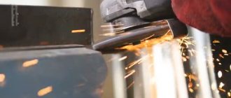
In most cases, grinding machines and center machining machines are used. Where grinding is performed using an abrasive cylinder rotating at high speed. However, in addition to this, there are machines that do not have a single axis of rotation, and the material is processed using several rotating cylinders. But what exactly is centerless grinding? How to work correctly with such a processing machine?
We offer the following types of metal grinding:
- Cylindrical grinding
- Surface grinding
- Centerless grinding
- Gear grinding;
- Thread grinding;
- Grinding.
Leave a request using the form or contact us by phone or e-mail
8 This email address is being protected from spambots. You must have JavaScript enabled to view it.
Cylindrical grinding includes two subtypes of grinding - external grinding and internal grinding .
External cylindrical grinding is grinding work on metal to obtain a cylindrical surface of increased precision. Processing occurs with a radial movement of the grinding wheel cutting into the workpiece. The maximum dimensions of workpieces for external cylindrical grinding are diameter up to 500 mm, length up to 1800 mm.
Internal cylindrical grinding is grinding work to remove allowance inside the cylinder, finishing after boring. The maximum dimensions of workpieces for internal cylindrical grinding are diameter up to 400 mm, length up to 1200 mm.
Surface grinding In this case, the part is mounted on a magnetic plate of a surface grinding machine. This type of processing ensures high flatness and parallelism of surfaces. Dimensions of processed parts – up to 800*400 mm. Processed parts: dies, rings, plates, knives, etc.
Centerless grinding Used in large-scale production for processing internal and external surfaces (bearing races, shafts, etc.). Processing is carried out in two circles located opposite each other. The part is based on a support knife between them.
This is interesting: Cold welding for metal - used correctly
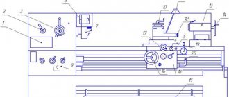
Kinematic diagram of the 3M182 cylindrical grinding machine
Kinematic diagram of the 3m182 cylindrical grinding machine
Rice. 3. Kinematic diagram of the machine:
- grinding wheel head;
- grandmother of the leading circle;
- plunge mechanism;
- straightening devices
- straightening devices
Characteristic
In factories and even in large metalworking workshops, a centerless grinding machine is often found. Its parameters are good enough for the production of products in large batches. The highest possible rigidity of the technological system is achieved. This circumstance guarantees stability of processing and high quality of manufactured products. .
It is possible to significantly improve the technical parameters of manipulation, such as the speed of metal processing and the overall performance of the device, which, of course, engineers take full advantage of.
An important advantage of centerless grinding is the minimal time spent on auxiliary operations. It makes up no more than 2-3% of the total operating time. When using other machines this figure is significantly higher. Therefore, we can confidently say that grinding equipment without a center has much less idle time in the operating cycle and is characterized by increased configuration flexibility. Setting it up in the desired way is not difficult. The main components of such a device :
- bed;
- metalworking headstock;
- fixed support with working knife;
- another grandmother;
- panel containing the control system.
Types of treated surfaces
- screw;
- flat (mold matrices);
- curvilinear;
- cylindrical;
- straight;
- conical;
- holes;
Surface roughness after grinding
Sanding belongs to the category of finishing operations and provides high quality surfaces. One of the qualitative characteristics of a surface is roughness. Depending on this parameter, grinding operations are:
1) Preliminary . It is performed on an untreated surface to remove the outer defective layer, or after rough turning or milling, but before heat treatment. Provides roughness within grade 5 – 7 . 2) Finishing . The operation is performed after pre-treatment, using grinding wheels with a finer grain size. The parts are polished after being heat-treated. Roughness grades 7–9 are obtained . 3) Thin . Used to obtain surfaces of 9–10 class cleanliness . Allowance for processing is minimal. 4) Finishing operation . Otherwise called “nursing.” This is obtaining high-precision dimensions of roughness class 11 - 12 by longitudinal feed of the grinding wheel without allowance for processing. In this case, the elimination of ovality and runout of the treated surfaces is achieved.
Description of the operation of hydraulic equipment during machining using the plunge method
The electric motor of the hydraulic drive pump is turned on by pressing the “Lubrication” button when the operating mode switch is set to the “Adjustment mode for plunge grinding” position, and by pressing the lever “Start the plunge cycle” the plunge is carried out. The speed of rapid approach of the grinding head and the sequence of its approach with the movement of the copier are adjusted during assembly. The working feed speed is controlled by a throttle with regulator 12 (Fig. 4).
When the electric motor is turned on, driving the double vane pump 2, the oil flows approach the pressure spools 4(1), 4(2) and through filters 3(1), 3(2) along lines 1 and 1' are supplied to the distributors.
Types of centerless grinding
There are two main methods - with longitudinal and transverse feed. Below we will briefly look at both methods.
Centerless machining with longitudinal feed
This processing technology is suitable for parts with a constant diameter over the entire surface (pipes, bolt blanks, uniform rods, etc.). During operation of the machine, the part, in addition to stabilizing rotation, can move in the longitudinal direction, which helps the master to better control the grinding. The rotating cylinders are not located parallel to each other, but at a slight angle.
Therefore, when the abrasive wheels rotate, the part can carry out longitudinal advancement of the material, and the greater the angle of inclination, the higher the speed of movement (the operator can change the angle of inclination manually). You need to choose the angle of inclination depending on several parameters - the total length of the part, its diameter, the quality of processing, and so on. Recommendation standards:
- Small workpieces of medium thickness - from 1 to 2.5 degrees.
- Long parts of medium and large thickness - from 1.5 to 3.5 degrees.
- Very small workpieces of any diameter - from 3 to 4.5 degrees.
Please note that these standards apply only to rough grinding - when finishing, the angle of inclination must be reduced by 20-30% to obtain a smooth, uniform surface. Longitudinal grinding should be carried out in several passes. During roughing passes, about 0.1-0.2 millimeters of metal is removed from the surface, and during finishing – 0.02-0.05 millimeters (subject to the standards specified above).
Cross feed grinding (plunge)
This technology is used for processing parts that have various protruding parts, recesses or grooves on the surface (objects of complex shape, jagged things, shaped composition products, etc.) that need to be preserved. The product is fed to the grinding shaft by the leading element perpendicular to the axis of rotation - this allows you to grind the product not as a whole, but in its individual parts. General instructions for using a centerless grinding machine using plunge-in technology look like this:
- Before starting the device, the drive shaft is removed from the grinding shaft, and then the part to be processed is placed on the supporting structure.
- To prevent the workpiece from moving in the longitudinal direction, it is pressed against the supporting structure using a special stop. The stop itself simultaneously serves as a pushing device.
- A guide shaft operating at low speed is brought to the surface, which transmits the rotation of the part. After this, the workpiece is brought to the grinding wheel using a guide shaft.
- During operation, the operator has the ability to control the depth of processing using a guide wheel.
If necessary, the abrasive wheel can be rotated slightly so that the axis of rotation is not strictly perpendicular, but at a slight angle. This procedure may be necessary when you need to firmly press the workpiece against the stop.
Centerless external grinding
Centerless external grinding is distinguished by the fact that the workpieces being processed are rotated and ground without fastening in the centers, and the base for grinding is the surface being processed. Centerless grinding is the most mechanized and productive process that can easily be automated.
During centerless external grinding (Fig. 1), both wheels rotate in the same direction at different speeds: the working wheel - at a speed of 30-35 m/s, the driving wheel - at a speed 60-100 times lower. The support for the workpiece to be ground is a knife with a beveled edge, located between the working and driving wheels. The knife is installed so that the center of the workpiece is above or below the line of circle centers. Workpieces located on the same axis as the circles will be non-circular in shape. Most workpieces are ground when they are mounted above the center line, with the exception of long thin parts such as bars, the center of which is located below the center line. In this case, the workpieces are pressed against the surface of the knife by cutting forces, and the grinding process proceeds more calmly, without the workpieces being thrown out of the grinding zone.
The position of the driving circle in relation to the working circle can be changed by setting the driving circle at different angles (0-6o). This allows the driving wheel during through grinding (the angle of rotation of the driving wheel during preliminary grinding is 2.5-6o, during final grinding 1-2o) to act as a feed mechanism, and during plunge grinding (the angle of rotation of the driving wheel is no more than 0.5o) to ensure a tight pressing the workpiece against the stop.
The workpiece being processed, located between the circles and resting on the surface of the knife, rotates at the speed of the leading circle. The rotation of the workpiece occurs due to the friction forces between it and the driving circle in the direction opposite to the rotation of the driving circle. The difference in speed between the working wheel and the workpiece being processed ensures the grinding process.
In centerless external grinding, processing is carried out with longitudinal feed of the workpiece by plunge grinding, as well as grinding with longitudinal feed to the stop (Fig. 2). When grinding with longitudinal feed of a workpiece (Fig. 2a), the longitudinal feed speed is determined by the formula S=V*sina, m/min, where V is the speed of the drive wheel, m/min, and is the angle of rotation of the drive wheel or the inclination of the support knife in degrees .
When grinding with longitudinal feed, the most common method of centerless grinding, the workpiece is passed into a gap between the working and driving wheels equal to the diameter of the workpiece minus the thickness of the layer removed in one pass. This method processes cylindrical workpieces (ball bearing rings, piston pins, cylindrical bearing rollers, pipes, studs, etc.).
When processing workpieces whose length is less than the height of the wheels, it is necessary to strive to ensure that the workpieces pass in a continuous flow in the working area of the machine without a gap between them. This creates stable operation of the machine, ensures stable dimensions of parts, and uniform wear of the working and driving circles. When grinding workpieces whose length is many times greater than the height of the wheels, heavy workpieces of large diameter, as well as narrow rings with a height of much smaller diameter, it is necessary to use special mechanisms that continuously feed the workpieces into the processing zone.
In cases where the shape of the workpieces does not allow the use of longitudinal feed (valves, bolts, journals of cardan shaft crosspieces and other stepped parts), plunge-cut grinding is used (Fig. 2b). With this grinding, the workpiece rests on the knife and receives rotation from the drive wheel. Allowance is removed from the surfaces being processed by moving the drive wheel perpendicular to the axis of the workpiece at the speed of its transverse feed. At the end of grinding, the leading wheel, together with the knife and the workpiece, is removed from the working wheel and the workpiece is changed. This type of grinding is easy to automate the process due to the use of a special shape of the drive wheel and the use of mechanisms for automatically loading and unloading the working area of centerless grinding machines.
Plunge grinding is widely used for simultaneous processing of journals of stepped workpieces, when it is necessary to ensure their high concentricity, as well as when processing workpieces of spherical and other profiles. Often in this case, multi-circle setups are used, in which a set of grinding wheels is mounted on special flanges, with bushings installed at a height corresponding to the non-grinding areas of the workpiece.
Grinding of workpieces using this method is carried out at various feeds and cutting depths. At the beginning of the process, most of the stock is removed with an increased depth feed, then the depth feed is reduced. At the end of processing, the workpiece is ground without applying depth. When plunge grinding, the number of transitions is less than when grinding with longitudinal feed, since large allowances can be removed during preliminary transitions.
An intermediate position between the considered methods of centerless grinding is occupied by grinding with longitudinal feed to the stop (Fig. 2c). This is how workpieces with surfaces limiting the passage of workpieces between the circles are processed: bolts, valves with a stem and plate, stepped rollers greater than the height of the circle, length, etc. When approaching the stop, the caliper carriage and the drive circle are moved away from the working circle, and the workpiece removed from the working area by an ejector.
For grinding the outer surfaces of workpieces, PP type wheels with an outer diameter of 250-750, a height of 40-250 mm and more on a ceramic bond are used as working wheels, and PP type wheels with an outer diameter of 200-350 mm, a height of 40-200 mm are used as driving wheels. on vulcanite or bakelite bonds. In rare cases, when it is necessary for one of the mounting flanges to be hidden in a recess, PV type wheels with an outer diameter of 500-600 mm are used.
For small centerless grinding machines, PVD type wheels with an outer diameter of 250-300 and a height of 75-100 mm are used as working wheels; wheels of this type on vulcanite and bakelite bonds with a diameter of 300-350 and a height of 100-275 mm are used as driving wheels. The presence of a recess on both sides of the circle allows you to use a shorter spindle for its fastening and almost completely hide the flanges in the recess.
Currently, when grinding workpieces with a diameter of up to 15 mm, cast iron and duralumin rollers are successfully used instead of vulcanite bonded driving wheels. Metal drive rollers have high durability between truings: no less, and in some cases even greater, than wheels on a vulcanite bond. Their use ensures high labor productivity and helps reduce the consumption of diamond tools (metal rollers are straightened to the required profile with carbide cutters, while only diamond tools are used to straighten vulcanite wheels).
The rigidity of the technological system (machine - grinding wheel - workpiece - drive wheel) during centerless grinding is 1.5-2 times higher than during cylindrical grinding of workpieces installed in centers, and even more so in a chuck. Therefore, with centerless grinding, the cutting conditions are correspondingly increased by 1.5-2 times, the processing of non-rigid workpieces (thin shafts, drills, etc.) is greatly facilitated, high stability of the dimensions of a batch of processed workpieces is ensured, and grinding allowances are reduced due to the basing of the workpieces on the surface being processed and their self-centering during processing. With centerless grinding, the auxiliary time associated with installation, alignment on the machine and removal of the workpiece is significantly reduced. When grinding with longitudinal feed, the auxiliary time is practically reduced to zero, since the workpiece processing process is carried out in a continuous flow. All this makes centerless grinding one of the most productive and efficient types of external grinding of workpieces.
Currently, centerless grinding is becoming even more developed and used due to an increase in the operating speed of the wheel to 60 m/s. Thus, increasing the working speed of the wheel from 30 to 60 m/s during plunge-cut grinding reduces the roughness of machined surfaces by approximately one class, allows you to increase the transverse feed speed of the driving wheel up to 2 times and, accordingly, increase the cutting depth, and increases the grinding coefficient by reducing wheel wear. 1.5-3 times. With an increase in the operating speed of the wheels, a decrease in errors in the geometric shape of the processed surfaces is observed due to a decrease in cutting forces and an increase in the stability of the grinding process. Increasing the operating speed of the wheel allows the centerless grinding cycle to be reduced by up to 2-4 times compared to the commonly used grinding process at the operating speed of the wheel ~30 m/s.
General concept of grinding
- In primitive cases, use hard granular sand or harder emery, pour it onto a hard surface and rub the object being processed against it. The angular grains, rolling between both surfaces, produce a large number of impacts, from which the protruding places of these surfaces are gradually destroyed, and the grinding grains themselves are rounded and disintegrated into pieces. If one of the surfaces is soft, the grains are pressed into it, remain motionless, and produce a series of parallel scratches on the second surface; in the first case, a matte surface is obtained, covered with uniform pits, and in the second, a so-called “stroke” gives the surface a shine that turns into polishing, when the stroke is so small that it becomes invisible to the eye. So, when grinding two copper plates against each other with emery, both will turn out matte, and the same emery, being glued to the surface of the paper, will impart shine when rubbed against the brass surface.
- Fragile, hard glass wears off more than a soft and elastic metal plate, and diamond powder can wear off the surface of the diamond itself, and pieces of quartz can be processed on a sandstone sharpener. The pits produced by the grains of emery are smaller, the finer the grains themselves; Therefore, grinding can produce the most precisely machined surfaces, as is done when grinding optical glasses.
This is interesting: Hole processing: types of operations and tools used
Principle of operation
The workpiece is not fixed in the clamping devices. It is placed in a special position, ensuring the simultaneous use of 2 grinding wheels at once. The knife located below is responsible for mechanical support.
Attention: the axis of rotation of the part is raised compared to the axis of the abrasive elements. One circle has a leading role, and the other has a driven role.
The dominant circle rotates at a speed of 10-50 m per minute. The speed of circulation of the driven circle is much higher, it can reach 30-35 m/s. The leading block is usually made using a vulcanite binder. The workpiece being processed rotates faster than this block. But the difference is small and usually ranges from 1 to 3%. If it exceeds this figure, special tuning is often required.
Speaking about centerless grinding methods, it is worth considering that they all come down to 2 options. Sometimes you have to work with long workpieces with a constant grinding diameter along the entire length. Then you need to feed the part in the longitudinal plane. But the mortise (cross-feed) method also plays an important role. It is used if:
- there are grooves on the surface;
- the product contains protrusions;
- the workpiece has a stepped or shaped configuration.
Plunge grinding works well if the workpiece has a continuous cross-section throughout. This is why it is recommended:
- for pipes for various purposes;
- semi-finished bolts and screws;
- rods with a homogeneous structure.
Sometimes stabilizing rotation is supplemented by longitudinal shear. This technique increases the control of grinding manipulations. They try to position the working cylinders not strictly parallel, but with a certain small angle. By increasing its value, operators increase the pace of work. But at the same time, it is important not to get carried away beyond measure, otherwise the quality begins to suffer.
This nuance is especially important during the final processing of workpieces. Only strict limitation of the angle makes it possible to achieve smoothness and uniformity of the entire surface.
The supply of lubricant through the pump allows you to effectively remove scale (rust) and perform other manipulations. Air-oil systems are specifically optimized to operate at the fastest possible rotation speed. The transfer of cutting fluid occurs through a special pipeline inside the machine. Electrical and hydraulic lubrication and cooling systems can also be used. Typically, not only cooling, lubrication, but also all other functions are controlled from a single command panel.
Kinematics of a centerless grinding machine model 3M182
The main movement - rotation of the grinding wheel - is produced from the M1 electric motor (7.5 kW; 1450 rpm) through a 188/140 V-belt drive (Fig. 3). The drive circle rotates through a 3/30 worm gear from the M2 electric motor (0.85 kW; 120–1650 rpm, stepless control).
Accelerated transverse movement of the grinding wheel head along the rolling guides is carried out from the M3 engine, manual movement - from the P4 flywheel. In both cases, the movement from shaft IV is transmitted through a 1/50 worm gear to the running nut. With a stationary screw in 4 mm increments, the nut rotates and moves the headstock. With each press, the push handle РЗ ensures rotation of shaft IV by one dial division (through the ratchet mechanism X with wheel 80).
During plunge-cut grinding, a hydraulic mechanism operates, moving the lead screw V along its axis (without rotation) together with the grinding headstock. In cylinder C2, the piston rod is rigidly connected to the lead screw V. A groove is made in the rod through which the wedge K passes, and a roller resting against the wedge is fixed. The pressure in the right cavity of the C2 cylinder moves the headstock to the left. When oil is supplied to the left cavity, the headstock is quickly retracted until the roller rests against the wedge. Then the wedge is gradually pulled out of the groove by cylinder C1 - the headstock continues to move to the right and cutting occurs. When the thrust collar of the rod reaches the body, the headstock stops and nursing begins (the wedge, having come off the roller, continues to move until it stops). At the end of grinding, cylinder C2 retracts the headstock. Screws with handles P1 and P2 regulate the stroke of the pistons in both cylinders. When grinding “on pass”, the screw with handle P1 must be screwed all the way into the body. Devices for dressing the wheels are installed on the headstocks of the grinding and driving wheels. Dressing of wheels is carried out by standardized devices, each of which imparts longitudinal movement to the diamond pencil A from the M4 engine (0.09 kW; 1500 rpm) or from the P5 handle (lead screw pitch 2 mm), transverse movement from the P6 handle (lead screw pitch screw 1.5 mm). Clutch M is safety. Setting the drive wheel headstock to the size of the workpiece during adjustment is carried out using the P7 handle using a screw with a pitch of 6 mm. In addition, the headstock of the driving circle rotates in a horizontal plane. After the necessary installation, the headstock is fixed using clamps. 7. Operating principle of the machine model 3M182 The workpiece is installed between the grinding and driving wheels on the support knife so that the centers of the part are slightly higher than the line of the centers of both wheels. The grinding wheel is given a fast rotational movement, the peripheral speed of which must correspond to the cutting speed adopted for the grinding operation and must be directed at the point of contact with the workpiece towards the support knife.
The driving wheel is also given a rotational movement in the same direction as the grinding wheel, but with a lower speed of circular feed of the part (10–50 m/min). The system of forces acting on the part from the abrasive wheels and the support knife causes it to rotate at a peripheral speed almost equal to the rotation speed of the drive wheel. The slide with the support knife and the drive wheel headstock is installed so that the distance between the abrasive wheels exactly corresponds to the specified diameter of the workpiece. When working with the longitudinal feed method, the axis of the driving wheel is set at a small angle (for rough grinding α = 1.5...6°, and for finishing α = 0.5...l.5°) to the axis of the workpiece, as a result of which an axial component of the circumferential the force under which the part moves along its axis. When working with the cross-feed method, the axis of the driving circle is located parallel to the axis of the part or at a slight angle of inclination (no more than 1°). There is no longitudinal feed in this case. Radial feed is communicated to the headstock of the driving circle. Figure 1 shows a scheme for grinding on centerless grinding machines the outer surface of a part with longitudinal feed “per pass”. Part 3, supported by knife 4, is located between two wheels 1 and 2, of which 1 is a grinding wheel, rotating at a peripheral speed of 30–40 m/sec, removing allowance from the workpiece, and 2 is a driving wheel, rotating at a peripheral speed of 10–50 m/min imparts rotation to the workpiece - circular feed. The longitudinal feed is imparted to the workpiece being ground by the leading wheel as a result of its installation at a certain angle to the axis of the grinding wheel or due to the tilting of the support knife at an angle α.
Application
A centerless grinding machine allows you to process structures with different external surfaces:
- conical;
- cylindrical;
- shaped.
The through grinding method is used if you need to work:
- with piston or piston pin;
- bushing;
- lead screw;
- technical shaft.
This involves running the part inside the entire machine (hence the name). Grinding until it stops is necessary if there are protrusions . Scoring is used almost exclusively for shaped structures. With it, the adjusting circle is fed in the transverse plane. The feed rate per revolution ranges from 0.0003 to 0.002 cm.
When working with conical workpieces, the axis of the main circle is tilted by 0.5-1°. The knife that creates the support is tilted to half the cone angle of the part. In this option, all the circles experience a powerful load, and they will need to be corrected much more often. To prevent the shape of the treated surface from being lost, use a soft spring stand. Grinding with a rigid support is recommended for parts with thin walls.
It is worth noting that centerless grinding machines have noticeable weaknesses. Thus, when processing hollow products, they do not allow achieving maximum concentricity of cylindrical surfaces. It will not be possible to ensure concentricity when working with a stepped roller. The necessary parameters are achievable, but the corresponding manipulations are economically justified only for large series. The centerless grinding machine in through-run mode guarantees an accuracy of up to 0.005 mm.
Model overview
There are a number of good models.
3M182
The device is designed for cylindrical grinding of metal. A special feature of this machine is the use of a horizontal spindle. The designers claim that their development is suitable for surfaces:
- stepped;
- smooth;
- cone-shaped;
- shaped on bodies of rotation with a cross-section from 0.08 to 2.5 cm.
The permissible length of the treated surface is normally up to 95 mm.
Its maximum value is 170 mm. Preliminary heat treatment is not essential. It is possible to work not only with metal, but also:
- with plastics;
- glass;
- textolite.
Features of work:
- non-roundness no more than 1 micron;
- the resulting surface roughness is at level V10;
- ensuring the first and second ranks in accuracy;
- presence of an automatic plunge-cut grinding cycle;
- Possibility of processing with through feed and advancing method.
3M184
Its parameters:
- the outer diameter of the circle is from 40 to 50 cm;
- up to 1370 turns per minute;
- circle hole 30.5 cm;
- spindle tip diameter 8 cm;
- maximum movement of the headstock on the dominant circle is 30 cm;
- weight 6850 kg.
ZE184
Its working diameter is 8 cm. There are modifications designed for higher and even precision accuracy. The line also includes versions with programmable controllers. The smallest cross-section of processed workpieces is 4 mm, the largest (in some variations) is up to 125 mm.
ZA184
Machine characteristics:
- works with parts up to 16.5 cm in length and up to 8 cm in diameter;
- has a mass of 5670 kg;
- has category B accuracy;
- develops a force of 13 kW.
Location of controls for the 3M182 centerless grinding machine
Location of controls for centerless grinding machine 3m182
List of components of the 3M182 centerless grinding machine
- 2. Infeed unit
- 3. Grinding wheel head
- 4. Plunge commutation
- 5. Plunging mechanism
- 20. Electrical cabinet
- 22. Setting for through and plunge grinding
- 23. Driving wheel editing mechanism
- 24. Headstock of the driving circle (non-rotating part)
- 43. Headstock of the driving circle (turning part)
- 51. Grinding wheel housing
- 52. Lamp
- 56. Control panel bracket
- 57. Electrical equipment of the plunge mechanism
- 58. Electrical equipment
- 60. Cooling communication
- 61. Electrical cabinet lock
- 62. Electrical cabinet base
- 63. Lubrication unit
- 65. Grinding wheel drive
- 68. Grinding wheel drive housing
- 69. Cooling unit
- 70. Caliper base
- 71. Through grinding support (rear)
- 72. Plunge grinding support
- 75. Drive wheel feed bracket
- 79. Through grinding support (front)
- 83. Grinding wheel dressing mechanism
List of controls for the 3M182 grinding machine
- 1. Flywheel and feed mechanism dial
- 6. Screw for adjusting the working stroke of the plunger mechanism piston
- 7. Screw for moving the carriage of the plunging mechanism
- 8. Stopping the longitudinal movement of the diamond carriage
- 9. Ruler reversal screw
- 10. Installation location of the copier alignment indicator
- 11. Diamond feed dial
- 12. Editing speed regulator
- 13. Quill withdrawal handle
- 14. Button for rapid retraction of the grinding headstock (to the left)
- 15. Main switch
- 16. Switch for machine operating modes “Adjustment mode”, “Plunge grinding” (semi-automatic) and “Pass grinding”
- 17. “Stop circle” button
- 18. Button “Start grinding wheel”
- 19. “All stop” button
- 21. Signal light “Machine on”
- 22. Signal light “No lubrication”
- 23. Ammeter
- 24. “Stop cycle” button
- 25. Lubrication button
- 26. Button “Start leading circle”
- 27. Button for rapid advance of the grinding head (to the right)
- 28. “Start editing” button
- 29. Switch “Grinding wheel dressing”, “Drive wheel dressing”
- 32. Lamp
- 33. Straightening mechanism clamp nuts
- 34. Rotation scale for the straightening mechanism
- 35. Screws securing the rotating part of the drive wheel headstock
- 36. Turning screw for the turning part of the drive circle headstock
- 37. Drive circle speed regulator
- 38. Scale for reversing the turning part of the driving circle headstock
- 40. Headstock clamp screw
- 41. Handle “Start the plunge cycle”
- 42. Plate clamp
- 44. Screw for tightening the front support of the drive circle
- 45. Bearing shell adjustment screws
- 46. Caliper base clamp handle
- 47. Caliper cheek adjustment screws
- 48. Screws for adjusting the knife height
- 49. Caliper reversal screws
- 50. Knife mounting screws
- 53. Diamond offset screw
- 54. Plunge speed regulator
- 55. Screw for adjusting the amount of rapid advance of the grinding head
- 59. Time relay
- 64. Screws for fixing the engine plate
- 66. Main drive belt tension screw
- 67. Duplicate button “All stop”
- 73. Leadstock zero position scale
- 74. Screw for moving the drive wheel headstock
- 76. Screw for turning the headstock of the driving circle in the horizontal plane
- 77. Table for calculating the turn of the headstock of the driving circle
- 78. Installation location of the driving circle headstock reversal indicator
- 80. Cooling valve when grinding
- 81. The valve for turning on the cooling on the diamond when dressing the grinding wheel
- 82. Jog handle (compensation)
- 83. Grinding wheel dressing mechanism
Manual
The workpiece is installed as carefully as possible before grinding. Adjustment contains 2 stages: one helps to process parts more accurately across the diameter, and the other helps longitudinally. The middle of the part is placed above the center line. For more efficient grinding, the support knife is placed with a bevel. Additional recommendations:
- adjust the machine using a device placed on the supporting plane of the knife support;
- when choosing the rotation speed of the workpiece, take into account the required quality and safety of work;
- use coolant at a rotation speed of the part faster than 50 m per minute;
- take into account fluctuations when cutting.
Cyclogram of the 3M182 cylindrical grinding machine
Cyclogram of operation of cylindrical grinding machine 3m182
By pressing the “Start the plunge cycle” button, the electromagnet 2EM of spool 8(2) is turned on. As a result of turning on the electromagnet 2EM, the sample will be loaded into the grinding zone and the limit switch 4VK will be pressed (Fig. 5), which will turn on the electromagnet 1EM of spool 8(1). As a result of turning on the electromagnet 1EM, the grinding headstock will be quickly brought to the product and the spools 11 and 9 will be activated. The piston of the hydraulic cylinder 14 of the copier will be able to move at a speed corresponding to the working feed of the grinding wheel. Simultaneously with the switching on of the electromagnet 1EM, the time relay PB is switched on (see Fig. 5), which controls the processing time of the part in the grinding zone. At the end of processing, the time relay is activated and turns off the 1EM electromagnet. The grinding head and the copier return to their original position, the limit switch 4VK is pressed, turning off the electromagnet 2EM of spool 8(2). The processed part is pushed out of the grinding zone, the limit switch 4VK is turned off. The ejector is located in the sample loading area. By pressing the “Start plunge cycle” lever, the cycle is repeated.
Features of the technology
The adhesion of the part to the surface of the leading abrasive wheel is ensured by its rotation, and the higher the rotation speed, the more reliable and stable the adhesion will be. A working machine has one characteristic feature - the lower the axial rotation speed of the guide element, the better the cutting abrasive wheel will work (that is, the cutting force is inversely proportional to the rotation speed of the guide element). Therefore, in most cases, vulcanization or some other rubber coating is applied to the guide wheel to further increase the adhesion force of the part.
Centerless grinding is widely used in large modern enterprises where the production and processing of parts is carried out in large batches. This technique is mainly used for machining external surfaces only, although if necessary it can be adapted for turning some through and internal holes. Centerless grinding of external surfaces has many advantages:
- The technique significantly reduces the time for processing one part. This allows you to speed up production and save on energy costs.
- The combination of the previous factors ultimately leads to a reduction in production costs, which has a beneficial effect on the competitiveness of the company's products in the market.
- The technology is simple; the master will master the technology almost from the first approach to the machine.
- The rotation of the guide element reliably stabilizes the workpiece, so grinding is very high quality and precise.
- The machines do not require special care or adjustment; The rubber coating on the guide element lasts quite a long time, and if necessary, it can be quickly replaced.
Cylindrical grinding of parts
Cylindrical grinding of parts is used in the manufacture of many products. Such as plungers, rods, pistons, cutting rings, punches and many others.
As a rule, these are parts that have special requirements. Special surface finish, dimensional accuracy.
Often the process takes place in two stages, since the parts require both external and internal sanding.
High qualifications and extensive experience of our production employees allow us to guarantee high quality processing of any manufactured product.
Centerless cylindrical grinding machine 3M182
| Parameter name | 3M182 | — |
| Main settings | ||
| The largest guaranteed diameter of the installed product, mm | 25 | |
| The largest permissible diameter of the installed product, mm | 35 | |
| Minimum diameter of the installed product, mm | 0.8 | |
| Smallest diameter recommended for plunge grinding | 2,5 | |
| Maximum length of processed products (limited by the rigidity and stability of the products) during through grinding, mm | 170 | |
| Maximum length of processed products (limited by the rigidity and stability of the products) during plunge-cut grinding, mm | 95 | |
| Height from the base of the machine to the axis of the circles, mm | 1060 | |
| Height from the bridge mirror to the axis of the circles, mm | 160 | |
| Grinding wheel | ||
| Maximum outer diameter, mm | 350 | |
| Smallest outer diameter, mm | 280 | |
| Maximum height, mm | 100 | |
| Hole diameter, mm | 203 | |
| RPM | 1910 | |
| Peripheral speed, m/sec | Up to 35 | |
| Leading Circle | ||
| Maximum outer diameter, mm | 250 | |
| Smallest outer diameter, mm | 200 | |
| Maximum height, mm | 100 | |
| Hole diameter, mm | 127 | |
| Maximum angle of inclination in the vertical plane, degrees | ±5 | |
| Maximum tilt angle in the horizontal plane, min | ±30 | |
| RPM during operation (stepless regulation) | 17—150 | |
| Number of revolutions per minute when straightening | 300 | |
| Grinding head | ||
| Grinding wheel spindle end size according to GOST 2323-67, mm | 80 | |
| Maximum installation movement, mm | 90 | |
| The greatest accelerated movement during plunge-cut grinding, mm | 20 | |
| Working movement per one division of the feed mechanism dial, mm | 0,001 | |
| Working movement per one revolution of the feed mechanism dial, mm | 0,08 | |
| Working movement of jog feed from the handle, mm | 0,001 | |
| Working displacement by plunge mechanism, mm | Up to 0.95 | |
| Feed rate during plunge-cut grinding is the highest, mm/min | 10 | |
| Feed rate for plunge-cut grinding is the lowest, mm/min | 0,06 | |
| Grandmother | ||
| Maximum displacement, mm | 80 | |
| Movement of the feed screw dial by one division, mm | 0,05 | |
| Movement of the feed rate dial per revolution, mm | 6 | |
| Wheel dressing mechanism | ||
| Transverse movement of diamond per dial division, mm | 0,01 | |
| Transverse movement of the diamond per one revolution of the dial, mm | 1,5 | |
| Maximum speed of diamond movement in the longitudinal direction, mm/min | 250 | |
| The speed of diamond movement in the longitudinal direction is the lowest, mm/min | 30 | |
| Maximum rotation angle of the copier, gra | ±2 | |
| Caliper | ||
| Maximum adjustment movement of the caliper knife in height, mm | 10 | |
| Hydraulic drive of the plunge mechanism | ||
| Pump capacity, l/min | 12/8 (double) | |
| Nominal pressure, kgf/cm2 | 10 | |
| Hydraulic tank capacity, l | 100 | |
| Lubrication unit | ||
| Capacity of the grinding wheel head spindle bearing lubrication pump, l/min | 5 | |
| Capacity of the spindle headstock bearing lubrication pump, l/min | 1,6 | |
| Grinding wheel bearing tank capacity, l | 65 | |
| Capacity of the drive wheel bearing tank, l | 15 | |
| Cooling unit | ||
| Pump capacity, l/min | 45 | |
| Magnetic separator throughput, l/min | 50 | |
| Capacity, tank, l | 120 | |
| Drive, dimensions and weight of the machine | ||
| Type of supply current | AC three-phase, current frequency 50Hz | |
| Supply voltage, V | 380 | |
| Electric drive voltage, V | 380 | |
| Control circuit voltage, V | 110 | |
| Voltage of local lighting circuits, V | 36 | |
| Signaling voltage, V | 5,5 | |
| DC voltage, V | 110 | |
| Grinding wheel drive motor - type | AO2-51-4-S1 | |
| Grinding wheel drive electric motor - power, kW, | 7,5 | |
| Grinding Wheel Drive Motor - RPM | 1460 | |
| Drive circle drive motor - type | PBST-22-V | |
| Drive circle drive electric motor - power, kW | 0,85 | |
| Drive Circle Drive Motor - RPM | 2200 | |
| Electric motor for driving an electric machine amplifier - type | EMU-12A-S1 | |
| Electric motor for driving an electric machine amplifier - power, kW | 1,2 | |
| Electric machine amplifier drive motor - rpm | 2900 | |
| Hydraulic pump drive electric motor - type | AOL2-21-4-S1 | |
| Hydraulic pump drive electric motor - power, kW | 1,1 | |
| Hydraulic pump drive motor - rpm | 1400 | |
| Grinding wheel spindle bearing lubrication pump drive motor - type | AOL21-4-S1 | |
| Electric motor drive of the grinding wheel spindle bearing lubrication pump - power, kW | 0,27 | |
| grinding wheel spindle bearing lubrication pump drive - rpm | 1400 | |
| Electric motor drive for lubrication pump of drive wheel spindle bearings - type | AOL11-4-S1 | |
| Electric motor driving the drive wheel spindle bearing lubrication pump - power, kW | 0,12 | |
| driving wheel spindle bearing lubrication pump drive - rpm | 1400 | |
| Cooling pump drive motor - type | PA-45-S1 | |
| Cooling pump drive electric motor - power, kW | 0,15 | |
| Coolant Pump Motor - RPM | 2800 | |
| Magnetic separator drive motor - type | AOL11-4-S1 | |
| Magnetic drive electric motor - power, kW | 0,12 | |
| Magnetic drive motor - rpm | 1400 | |
| Grinding wheel dressing drive electric motor - type | PL-062-S1 | |
| Grinding wheel dressing drive electric motor - power, kW | 0,09 | |
| Grinding wheel dressing drive motor - rpm | 1440 | |
| Drive wheel dressing drive electric motor - type | PL-062-S1 | |
| Drive wheel dressing drive electric motor - power, kW | 0,09 | |
| Drive Wheel Dressing Motor - RPM | 1440 | |
| Electric motor for driving rapid movement of the grinding headstock - type | AOL12-4-S1 | |
| Electric motor for driving the accelerated movement of the grinding head - power, kW | 0,18 | |
| Grinding headstock rapid movement motor - rpm | 1400 | |
| Total power of electric motors, kW | 11,67 | |
| Machine dimensions (length X width X height), mm | 2230 x 1455 x 2120 | |
| Weight of the machine with attached equipment, kg | 3470 |
Moscow, Mechanical Engineering. Encyclopedia 2002. Edited by K.V. Frolova
Information about the manufacturer of the centerless cylindrical grinding universal machine 3M182
The manufacturer of the 3M182 centerless cylindrical grinding machine is the Vitebsk machine tool plant Vistan , founded in 1914.
In 1960, by government decision, it was decided to produce universal and special centerless grinding machines.
Vitebsk Machine Tools is one of the leading enterprises producing cylindrical grinding, center and centerless machines, gear cutting, CNC machining centers, lathes, special, mini, woodworking machines.
Products of the Vitebsk machine tool plant Vistan named after. S. Kirov
- 2A592
- radial drilling machine, Ø 25 x 130 - 2B118
- vertical drilling machine, Ø 18 - 3A184
- centerless cylindrical grinding machine, Ø 80 - 3E180v
- centerless cylindrical grinding machine, Ø 10 - 3E184
- centerless cylindrical grinding machine, Ø 80 - 3M182
- centerless cylindrical grinding machine, Ø 25 - 3M184
- centerless cylindrical grinding machine, Ø 80 - 5B312
- gear hobbing machine for cylindrical wheels, semi-automatic, Ø 320 - 5B312
- gear hobbing machine for cylindrical wheels, semi-automatic, Ø 320 - 5K310
- gear hobbing machine for cylindrical wheels, semi-automatic, Ø 200 - 16VT20p
– screw-cutting lathe, Ø 500 - 53A30P
- semi-automatic gear hobbing machine for cylindrical wheels, Ø 320 - 53V30P
- gear hobbing machine for cylindrical wheels, semi-automatic, Ø 320 - 371, 371M-1
- surface grinding machine with a horizontal spindle, 600 x 200 x 250 - 2206VMF4
- horizontal drilling-milling-boring machine with CNC and ASI, 630 x 800 - 3184
— centerless cylindrical grinding machine, Ø 75 - 5702
— semi-automatic gear shaving machine, 320 - VST-028
— tabletop screw-cutting lathe, Ø 200
Grinding metal surfaces
There is simply a huge number of different metal processing operations, all of which are characterized by the use of certain equipment and tooling. A common finishing process is the sanding process. It involves removing a small surface layer, due to which a certain roughness and more accurate dimensions are achieved. Let us consider the features of this process in more detail.
Metal grinding
The processing of metal and various alloys using an abrasive material is usually called grinding.
This technology allows you to change the roughness and other parameters of the outer or inner cylindrical, as well as flat surface.
Metal grinding can be carried out using various special equipment. When considering the features of such mechanical processing, you need to pay attention to the following points:
- The grinding process is the final stage of processing, which is carried out to obtain a certain roughness.
- This technology is not used to change sizes over a large range.
- Using modern equipment, the surface can be brought to the required roughness after heat treatment of the metal.
When carrying out the operation in question, a fairly large number of features are taken into account:
- Wheel speed is a parameter that depends on the outer diameter of the abrasive and the capabilities of the machine.
- Speed of movement of the part.
- Depth of cut.
- Possibility of cross feeding.
It is worth noting that today such technology is gradually being replaced by fine turning of metal at high speeds and minimal feed.
Main types of grinding
Grinding of parts can take place using a variety of technologies. The most widespread are the following:
- Circular grinding of metal.
- Changes in the roughness of internal surfaces.
- Gear grinding.
- Centerless technology.
- Sanding flat surfaces.
In addition, classification can be carried out according to the type of material used during processing. To automate the process and reduce labor costs, specialized machines are used. There are also models with a built-in CNC unit, which automates the process and ensures high quality of the resulting surface.