ang=»ru»>
Color wiring diagram of screw-cutting lathe 16K20VF1
It is difficult to understand an electrical circuit with many similar elements. To make it easier to find the desired element on the diagram, as well as to distinguish elements marked the same way, I added colored geometric shapes to the designations. Identical shapes mean that the elements next to them belong to the same device (for example, a contactor, relay or switch). I call this technology colorism. I made the description in two versions: I made the description in two versions:
- One with the need to scroll. I did this so that when reading the description the diagram would not go out of sight).
- Other traditional
Use the form that you find more convenient. The machine's passport with a description of the electrical circuit can be easily found on the Internet.
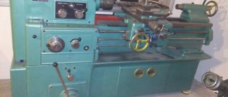
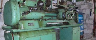
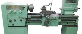
Screw-cutting lathe 16K20
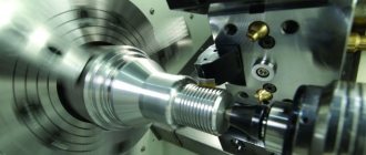
The 16K20 screw-cutting lathe is designed to perform a variety of turning operations: turning and boring cylindrical and conical surfaces, cutting external and internal metric, inch, modular and pitch threads, as well as drilling, countersinking, reaming, etc. Deviation from cylindricity is 7 microns, taper is 20 microns at a length of 300 mm, deviation from straightness of the end surface at a diameter of 300 mm is 16 microns. However, there are 16K20 machines without a lead screw. On such machines you can perform all types of turning work, except for cutting threads with a cutter.
The machines are equipped with a mechanical clutch, a drive for rapid movements of the caliper, the tailstock has aerostatic unloading, the bed guides are hardened HRCе 49...57.
The technical parameters by which screw-cutting lathes are classified are the largest diameter D of the workpiece (part) being processed or the height of the centers above the bed (equal to 0.5 D), the greatest length L of the workpiece (part) being processed and the weight of the machine. A number of the largest processing diameters for screw-cutting lathes look like: D = 100, 125, 160, 200, 250, 320, 400, 500, 630, 800, 1000, 1250, 1600, 2000 and further up to 4000 mm. The greatest length L of the workpiece is determined by the distance between the centers of the machine. Manufactured machines with the same value of D can have different values of L. By weight, lathes are divided into light - up to 500 kg (D = 100 - 200 mm), medium - up to 4 tons (D = 250 - 500 mm), large - up to 15 t (D = 630 - 1250 mm) and heavy - up to 400 t (D = 1600 - 4000 mm). Lightweight lathes are used in tool production, instrument making, the watch industry, and in experimental and experimental workshops of enterprises. These machines are available with or without mechanical feed.
16K20T1 Location of lathe controls
Location of controls for lathe 16K20T1
16K20T1 List of lathe controls
- Machine control panel
- Spindle speed range setting handle
- Manual Caliper Movement Generator
- Socket for the handle for transverse movement of the caliper
- Tailstock quill clamp handle
- OSU system control and display panel
- Tailstock clamp handle on bed
- Emergency stop button
- Axis of manual movement of the carriage
- Emergency cam release button
- “Control panel lock” switch
- Cooling switch
- Quill travel pedal (double)
- Switch "Start", "Stop" of spindle and feed
- Bulb
- Chuck control pedal
- Spindle speed shift knob
Technical characteristics of the machine 16K20
The technical characteristics of the 16K20 machine are the main indicator of the machine’s suitability for performing certain jobs. For screw-cutting lathes, the main characteristics are:
- largest diameter D of the workpiece (part) being processed
- greatest distance between RMC centers
- maximum length of the workpiece
- spindle revolutions per minute
Below is a table with the technical characteristics of the 16K20 screw-cutting lathe. More detailed technical characteristics of the screw-cutting lathe can be found in the passport of the machine 16K20
| Quantities | ||
| Accuracy class | N | |
| The largest diameter of the workpiece being processed above the bed | mm | 400 |
| Largest turning diameter over cross slide | mm | 220 |
| The largest diameter of the processed bar | mm | 50 |
| Maximum length of the processed product | mm | 710, 1000, 1400, 2000 |
| Spindle speed limit | rpm | 12,5-1600 |
| Feed Limits | ||
| - longitudinal | mm/rev | 0,05-2,8 |
| - transverse | mm/rev | 0,025-1,4 |
| The greatest force allowed by the feed mechanism at the stop | ||
| - longitudinal | kgf | 800 |
| - transverse | kgf | 460 |
| The greatest force allowed by the feed mechanism on the cutter | ||
| - longitudinal | kgf | 600 |
| - transverse | kgf | 360 |
| Main drive motor power | kW | 11 |
| Machine dimensions (Length) | ||
| - length | mm | 2505, 2795, 3195, 3795 |
| - width | mm | 1190 |
| - height | mm | 1500 |
| Machine weight | kg | 2835, 3005, 3225, 3685 |
Passport for screw-cutting lathe 16K20
This operating manual “ Passport for screw-cutting lathe 16K20 ” contains information necessary both for the maintenance personnel of this machine and for the employee directly involved in working on this machine. This manual is an electronic version in PDF format of the original paper version. This documentation contains the Passport and Manual (instructions) for the operation of the universal screw-cutting lathe 16K20.
Content
- Introduction
- Unpacking and transporting the machine
- Removing anti-corrosion coatings
- Machine installation
- Preparing the machine for start-up
- Machine lubrication
- Electrical equipment of the machine
- Pneumatic equipment of the machine
- Controls
- Starting up the machine and some operating conditions
- Instructions for the use and installation of chucks and steady rests
- Machine mechanics
- Brief description of the main components and their regulation
- Kinematic diagram of the machine
- Bearing layout diagram
- Typical possible malfunctions.
- Repair.
- Instructions for carrying out accuracy control
- Machine passport
- Applications
You can download the passport of the screw-cutting lathe 16K20 in good quality using the links below:
Location of controls for the 16K20T1 lathe. Remote Control
Control panel for lathe 16K20T1
List of controls for the 16K20T1 lathe. Remote Control
- Button “Lubricate bed guides”
- Spindle Jog button
- Lamp "Presence of voltage"
- Minimum release switch of the input circuit breaker
- Mechanical interlocking of the minimum release switch of the input circuit breaker
- Introductory machine handle
- AKS lubrication control warning light
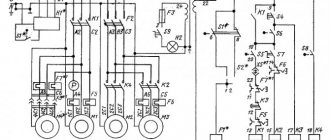
Electrical circuit diagram of a screw-cutting lathe 16K20
The electrical circuit diagram of the 16K20 screw-cutting lathe is shown in the following figure:
You can download a free electrical circuit diagram of a 16K20 screw-cutting lathe with specifications and in excellent quality from the link below:
16K20 screw-cutting lathe is shown in the following figure:
You can download this version of the electrical circuit diagram of a 16K20 screw-cutting lathe for free with specifications and in excellent quality from the link below:
Repair of screw-cutting lathe 16K20
Below are links to three albums dedicated to the repair of a 16K20 screw-cutting lathe . This documentation was developed by the State Design and Technological Institute for Modernization and Automation, Repair of Metal-Cutting Machine Tools and Maintenance of Metalworking Equipment with Software Control - GPKTI STANCOSERVICE.
Content
- General description of the machine
- Purpose and brief technical characteristics
- Controls
- Specification of main components
- Basic parameters of gears, worms, screws, nuts, racks
- Kinematic diagram
- Specification of rolling bearings
- Machine lubrication
- Lubrication map
- Description of the electrical circuit
- Electrical circuit diagram
- Machine electrical equipment specification
- Drawings of machine components
- Bed 16K20.010.001; 16K20.011.001; 16K20.012.001; 16K20.016.001
- Spindle head 16K20.020.001
- Tailstock 16B20.030.001; 16B20P.030.001
- Four-position tool holder 16K20.041.001
- Carriage and support 16K20.040.001 and 16K20.050.001
- Apron 16B20P.061.000
- Feed box 16B20P.070.000
- Gearbox 16K20.080.001
Download for free “Repair of screw-cutting lathe 16K20. Album 1. General description" in normal quality (70 pages) can be found at the link below:
Contents “Repair of screw-cutting lathe 16K20. Album 2. Technological process of major repairs"
- Route of a 16K20 screw-cutting lathe during a major overhaul
- List of equipment used during major repairs of the machine
- Route technological process of disassembling the machine into units
- Recommendations for defect detection and restoration of parts
- Route technological processes for parts repair
- Requirements for the quality of machine assembly
- Route technological process for assembling machine components
- Route technological process of assembly and debugging of the machine
- Testing the machine after a major overhaul
- Protocol for checking the machine for rigidity and accuracy according to GOST 18097-72
- Noise Level Standards and Test Methods
- Applications
Download for free “Repair of screw-cutting lathe 16K20. Album 2. Technological process of major repairs" in good quality (100 pages) can be found at the link below:
Contents “Repair of screw-cutting lathe 16K20. Album 3. Replaceable parts"
- Temporary norms for the consumption of replaceable parts when repairing a 16K20 machine
- Working drawings of replacement parts
Download for free “Repair of screw-cutting lathe 16K20. Album 3. Replaceable parts" in good quality (196 pages) can be found at the link below:
Description of the main components of a lathe with OSU 16K20T1
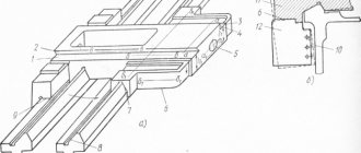
Headstock
The design of the spindle assembly (Fig. 2.6) largely determines the operational performance of the machine, i.e., the cutting modes used and the achieved accuracy and processing performance. Therefore, the headstock body 1 is made in the form of a rigid cast iron and is securely fixed to the frame. The gears are hardened and ground according to the tooth profile. The most important part of the spindle head is the spindle 5, which directly perceives the cutting forces. The front end of the spindle has a flange to which the jaw chuck is attached. The front support is a double-row tapered roller bearing 4, and the rear support is a single-row tapered roller bearing 3. The use of springs 2 in the supports, intended for constant selection of clearances in the bearings, helps to increase the accuracy and rigidity of the spindle assembly. The bearings are adjusted by the machine manufacturer, which ensures their operation without operator intervention (except in cases of repair).
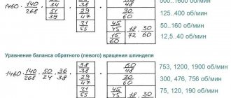
The spindle head provides manual switching of three speed ranges with the ratio: 1.17:1; 1:2; 1:8, which together with a 9-speed gearbox provides 22 spindle speeds in the ranges: 12.5..200; 50-800; 125-2000 rpm (9 speeds in each range) with the main version of the machine with an electric motor of 1460 rpm).
The spindle is mounted in double-row and single-row conical bearings. Bearings are adjusted at the machine manufacturer's factory and do not require adjustment during operation. The spindle head is installed with the spindle axis along the calculated line of the machine centers on the bed using two screws (see Fig. 5).
On the 16K20T1 machine without AKS, a spindle head with two electromagnetic clutches is installed, providing speed switching with a 1:2 ratio when manually setting the speed with two handles that move movable gear blocks. Spindle speeds for different positions of handles or clutches for functions M38, M39, see table.
Drive for longitudinal movement of the caliper
The drive for longitudinal movement of the caliper (Fig. 2.7) includes a ball screw gear (diameter 63 mm, pitch 10 mm), screw supports 2, gearbox 1 (gear ratio 1:1), DC electric motor 6 and feedback sensor 3 connected with screw via coupling 4.
If the machine is equipped with a frequency-controlled asynchronous motor, then a gearbox with a gear ratio of 1:2 is installed, and a feedback sensor is built into the electric motor. The gap in the gear mesh of the gearbox is selected by moving the adapter plate 5 (with the electric motor installed on it) relative to the gearbox housing.
Drive for transverse movement of the caliper
The drive for the transverse movement of the caliper (Fig. 2.8) includes a ball screw gear (diameter 40 mm, pitch 5 mm), screw supports 1, gearbox 2 (gear ratio 1:1), DC electric motor 5 and feedback sensor 4 connected with a screw using an elastic coupling 3. If the machine is equipped with a frequency-controlled asynchronous motor, then a feedback sensor is built into the electric motor. The gap in the gearing is selected by the vertical displacement of plate 6 (with an electric motor installed on it).
Six position turret
A six-position turret (Fig. 2.9) with a horizontal axis of rotation is installed on a transverse slide. Six cutter inserts or three tool blocks are mounted in the tool head.
The tool removable head is mounted on the output shaft 5 and is rigidly connected to the movable element 6 of the flat-toothed coupling. The turret head is rotated as follows: from the electric motor 2 (via a worm gear), rotation is transmitted to the shaft 7 of the cam coupling half 8, which is rigidly connected to the shaft 5. At the initial moment of rotation, the elements 3 and 6 of the flat-gear coupling are disengaged and the head rotates to the desired position, which is controlled by an electric sensor 10. Then the electric motor is reversed, the shaft 7 of the cam clutch rotates in the opposite direction, and the movable element 6 of the flat-toothed coupling (with the tool head) is kept from rotating by a lock, as a result of which element 6 is fixed on the teeth of the fixed element 3 of the flat-toothed coupling. The clamping signal from the limit switch 9 is supplied to the control panel, and the rotation motor is turned off and the processing cycle begins. For manual rotation and clamping of the turret head (when setting up the machine), a hexagonal wrench is provided on shaft 1. The cutting tool should be positioned as evenly as possible on the tool head to avoid imbalance when the head rotates.
Tailstock
The tailstock (Fig. 2.10) is mounted on the frame using handle 3, eccentric shaft 5, bar 8 and a lever system. The force of pressing the tailstock to the frame is adjusted with screws 7 and 2 (with lock nuts 6 and 1 released), changing the position of the clamping bar 8. The quill is moved manually (using a flywheel) or using an electromechanical drive 4.
Cartridge
The machine is equipped with a three-jaw chuck (Fig. 2.11) with an electromechanical drive for clamping the workpiece.
The cams 3 of the cartridge move in the radial direction as a result of the translational movement of the wedge 4 associated with the rod 5, which is connected to the rod 7 through a package of disc springs 6. The latter is connected by a screw-rod 8 to the electromechanical head 1, which is a special asynchronous electric motor, in the armature of which nut is built in. When the armature rotates, the screw-rod 8 moves in the longitudinal direction, driving the rod 7. The greater the amount of movement of this rod, the greater the compression force of the spring package and, consequently, the clamping force of the cartridge. This force can be adjusted by moving the proximity switches 2.
Machine lubrication 16k20t1
The machine uses an automatic spindle head lubrication system. The gear pump draws oil from the reservoir and delivers it through a strainer to the spindle bearings and gears. About a minute after the main electric motor is turned on, the oil indicator disk begins to rotate. Its constant rotation indicates normal operation of the lubrication system. The oil from the spindle head is drained into the reservoir through a mesh filter and a magnetic cartridge. During operation, it is necessary to monitor the rotation of the oil indicator disk; When it stops, you must turn off the machine and clean the filter by rinsing its elements in kerosene. The filter is cleaned as it becomes clogged, but at least once a month.
Every day before starting work, check the oil level at the oil indicator and, if necessary, add oil.
Lubrication of the carriage and bed guides is also carried out automatically from the C48-12 station installed on the base of the machine. When the pump is turned on, oil is supplied under pressure (via a hose) to the junction box on the carriage. The pump is turned on simultaneously with the machine turning on, and subsequently upon command from the time relay (with an interval of 10..240 minutes). When the pump is running, the warning light comes on. If necessary, you can add additional oil by pressing the “Lubricant Push” button.
The supports of the caliper feed screw pairs and the ball nut are lubricated manually (through an oiler) with plastic lubricant.
Proper and regular lubrication of the machine is essential for its normal operation.
Operating procedure of the machine
Before starting work, turn on the machine and check the position and reliability of fastening of the emergency travel limit cams on the longitudinal and transverse rulers, as well as the position and reliability of fastening of the tailstock on the frame (if used). When processing in a chuck, the tailstock is moved to the extreme right position. Using special handles, the ease of movement of the caliper in the longitudinal and transverse directions is checked. In the “Manual Control” mode, the operation of the machine mechanisms is checked: switching rotation speed ranges; movement of the caliper in the longitudinal and transverse directions at high speed and working feeds; operation of emergency and interlocking electrical switches; lubricant supply; spindle rotation, etc.
After checking the operation of the machine in manual mode and making sure that it is correct, turn on the automatic cycle - bypassing the circuit at idle (without installing the workpiece).
During normal operation of the machine, the first part is processed according to the NC, it is measured, and the CP is corrected using the CNC.