Control during installation of monolithic grillages
| Stages of work | Controlled Operations | Control (method, volume) | Documentation |
Prepared
works | Check: | General work log, acceptance certificate for previously completed work, passports (certificates) |
| — availability of certificates for previously completed work; | Visual |
| — correct installation and reliability of fastening of formwork, supporting scaffolding, fastenings and scaffolding; | Technical inspection |
| — preparedness of all mechanisms and devices that ensure the production of concrete work; | Visual |
| — cleanliness of the pile heads, the previously laid layer of concrete and the inner surface of the formwork; | Same |
| — presence of lubricant on the inner surface of the formwork; | Same |
| — the condition of the reinforcement and embedded parts, compliance of their position with the design; | Technical inspection, measuring |
| — a leader of the design mark for the top of concreting on the inner surface of the formwork. | Measuring |
| Laying concrete mixture, concrete hardening, stripping | Control: | General work log |
| — quality of the concrete mixture; | Laboratory |
| - condition of the formwork; | Technical inspection |
| - the height of dropping the concrete mixture, the thickness of the laid layers, the step of rearranging the deep vibrators, the depth of their immersion, the duration of vibration, the correct execution of working joints; | Measuring, 2 times per shift |
| — temperature and humidity conditions of concrete hardening; | Measuring, in places specified by PPR |
| - actual concrete strength and formwork removal time. | Measuring at least once for the entire volume of stripping |
| Acceptance of completed work | Check: | Acceptance certificate for completed work, as-built geodetic diagram |
| - actual strength of concrete; | Laboratory |
| — quality of the grillage surface, geometric dimensions of the grillage, compliance with the design position of the entire structure; | Visual, measuring, every structural element |
| — quality of materials used in the design. | Visual |
| Control and measuring instruments : plumb line, tape measure, metal ruler, level, theodolite, two-meter staff, tacheometer. |
| Operational control is carried out by : a foreman (foreman), a construction laboratory engineer, a surveyor - during the execution of work. Acceptance control is carried out by : quality service workers, foreman (foreman), surveyor, representatives of the customer’s technical supervision. |
| Note : operational control of the surveyor during the concreting process is possible only for the purpose of monitoring deformations; adjustment of the formwork at this moment is unacceptable, because affects the change in the continuity of the concrete mixture and the formation of voids in it. |
SNiP 3.02.01-87 “Earth structures, foundations and foundations.”, table. 18 (excerpts from the table) or SP 45.13330.2012 “Earth structures, foundations and foundations.”, table. 12.1 (extracts from the table),
| Parameter | Limit deviations | Control (method and volume) |
| 19. Displacement of the axes of the head relative to the axes of the pile | ± 10 mm | Measuring, each head |
SNiP 3.03.01-87 “Load-bearing and enclosing structures”, table. 11 or SP 70.13330.2012 “Load-bearing and enclosing structures”, table. 5.12
| Parameter | Limit deviations | Control (method, volume, type of registration) |
| 1. Deviation of the lines of the intersection planes from the vertical or the design slope to the entire height of the grillage | 20 mm | Measuring, each structural element, work log |
| 2. Deviation of horizontal planes over the entire length of the area being verified | 20 mm | Measuring, at least 5 measurements for every 50-100 m, work log |
| 3. Local unevenness of the concrete surface when checking with a two-meter strip, except for supporting surfaces | 5 mm | Same |
| (from JV) | depending on the class of concrete from 2 mm to 15 mm, see the table “Classes of concrete surfaces” below |
| 4. Grillage length | ±20 mm | Measuring, each element, work log |
| 5. Grillage cross-sectional size | +6 mm; -3 mm | Same |
| (from joint venture) with size | +6 mm |
| (from SP) with size = 400 mm | +11 mm; -3 mm |
| (from SP) with size > 2000 mm | +25 mm; -9 mm |
| (from SP) intermediate dimensions are interpolated |
| 6. Markings of surfaces and embedded products that serve as supports for steel or precast concrete columns and other precast elements | -5 mm | Measuring, each support element, executive circuit |
| 7. Slope of the supporting surfaces of foundations when supporting steel columns without grout | 0,0007 | The same, each foundation, executive diagram |
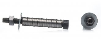
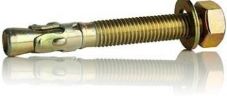
| 8. Location of anchor bolts: | The same, each foundation bolt, executive diagram |
| in plan inside the support contour | 5 mm |
| in plan outside the support contour | 10 mm |
| in height | +20 mm |
| 9. Difference in height marks at the junction of two adjacent surfaces | 3 mm | The same, each joint, executive diagram |
SP 70.13330.2012 “Load-bearing and enclosing structures”, Table X.1 - Classes of concrete surfaces
| Concrete surface class | Straightness tolerances for measured distances, mm |
| local unevenness (0.1 m) | 1m | 2 m | 3m |
| Note - Straightness tolerances are applied subject to tolerances on the thickness of the protective layer and on the cross-sectional dimensions (thicknesses) of the elements. If the surface class is not specified in the design documentation, then it is accepted as A6 or A7 depending on the purpose: A6 - surface without finishing or for simple painting, A7 - surfaces to be plastered and hidden. |
Material quality requirements
GOST R 52085-2003 “Formwork. General technical conditions." (excerpts)
6.2.5 For wooden load-bearing and supporting elements, round coniferous timber of grades I - II should be used in accordance with GOST 9463 “Round coniferous timber. Technical conditions", table. 2 (extracts from the table),
| Purpose of timber | OKP code | Wood type | Variety | Thickness, cm | Length, m | Length gradation, m |
| 14. For construction | 531441 | Pine, spruce, fir, larch | 1, 2 | 14 — 24 | 3,0 — 6,5 | 0,5 |
lumber of softwood species I - II grades according to GOST 8486 “Lawn softwood. Technical conditions".
6.2.6 For class 1 and 2 formwork decks, lined (laminated) birch plywood must be used; for class 2, combined lined plywood can also be used; for the 3rd class - softwood lumber in accordance with GOST 8486 “Coniferous lumber. Technical conditions" and hardwood according to GOST 2695 "Lumber of hardwood.
Technical conditions" not lower than grade II, particle boards in accordance with GOST 10632 "Particle boards. Technical conditions", fiberboards according to GOST 4598 "Fibreboards. Technical conditions", bakelized plywood according to GOST 11539 "Bakelized plywood. Technical conditions", FSF grade plywood according to GOST 3916.1 "General purpose plywood with outer layers of hardwood veneer. Technical specifications", GOST 3916.
2 “General purpose plywood with outer layers of softwood veneer. Technical specifications" and other materials.
Note - grades of timber and lumber are determined depending on the number and size of wood defects (knots, rot, etc.) according to the above-mentioned GOSTs.
GOST 23478-79 “Formwork for the construction of monolithic concrete and reinforced concrete structures. Classification and general technical requirements" (GOST is not valid in the Russian Federation)
4.14 Deck boards should have a width of no more than 150 mm, the moisture content of the wood used for the deck should be no more than 18%, for supporting elements - no more than 22%.
4.20 The formwork elements must fit tightly to each other during assembly. Gaps in butt joints should not be more than 2 mm.
GOST 10922-2012 “Reinforcing and embedded products, their welded, knitted and mechanical connections for reinforced concrete structures. General technical conditions", clause 5.3, table. 1 (excerpts from table)
| Linear size of the product and its nominal value | Maximum deviation of dimensions of products used in monolithic reinforced concrete structures |
| 1. The length of individual rods of non-prestressing reinforcement, the distance between the outer rods along the length, width or height of the product with their values: |
| from 500 to 1000 incl. | ± 10 |
| from 1000 to 1600 inclusive. | +10, -14 |
| from 1600 to 2500 inclusive. | +12, -18 |
| from 250 to 4000 incl. | +15, -30 |
| from 4000 to 8000 incl. | +20, -40 |
| from 8000 to 16000 inclusive. | +30, -50 |
| 2. The distance from the outermost rod of one direction to the end of the rod of the other direction (bar release length) in reinforcement products with the release length: |
| from 500 to 1000 incl. | ± 12 |
| 3. The distance between two adjacent longitudinal bars (except for the outer ones) in reinforcement cages with its values: |
| from 120 to 250 incl. | ± 10 |
| from 250 to 500 incl. | ± 12 |
| from 500 to 1000 incl. | ± 15 |
| 4. Length and width of the flat element of the embedded product: |
| 5. The same, if the dimensions of the flat element of the embedded product and the cross section of the reinforced concrete structure are equal: |
| 6. Distance from the flat element of the embedded product to the nearest point on the surface of the anchor rod: |
| from 120 to 250 incl. | + 10 |
| 7. Distance between the external elements of the product to the nearest point on the surface of the anchor rod: |
| 8. The length of the anchor rods of open-type embedded products with its value: |
| from 250 to 500 incl. | ± 12 |
| Note - the nominal distance between the rods is taken to be the size between their axes. |
5.6 The elements of reinforcement products and embedded parts should be free of flaking rust and scale, as well as traces of oil, bitumen and other contaminants.
GOST 23279-85 “Welded reinforcement mesh for reinforced concrete structures and products. Technical specifications"
3.15 Maximum deviations from straightness of mesh rods should not exceed 6 mm per 1 m of mesh length.
GOST 7473-2010 “Concrete mixtures. Technical conditions."
8.2 Before the start of delivery of a concrete mixture of a given quality, the consumer has the right to demand from the manufacturer (supplier) information about the quality of the materials used and the nominal composition of the concrete mixture, as well as the results of preliminary tests of the concrete mixture of a given nominal composition and concrete for all indicators specified in the supply contract. This information is presented in concrete composition selection cards.
8.4 When delivering a ready-mixed concrete mixture of a given quality, the manufacturer (supplier) must provide the consumer in printed and certified form with the following accompanying documentation:
- for each batch of concrete mixture - a document on the quality of the concrete mixture and a test report to determine the standardized quality indicators of concrete;
- for each load of concrete mixture - a delivery note;
- In addition (if specified in the supply contract), the manufacturer must provide the consumer with information in accordance with 8.2.
8.5 When delivering a ready-mixed concrete mixture of a given composition, the manufacturer must provide the consumer in printed and certified form with the following accompanying documentation:
- for each load of concrete mixture - a delivery note and a document on the quality of the concrete mixture;
- for each batch of concrete mixture - copies of passports for the materials used;
- Additionally (if specified in the supply contract), the manufacturer must provide the consumer with protocols for determining the quality indicators of the concrete mixture and concrete.
