Preparatory activities
The first thing to note is that the procedure for replacing capacitors is a very delicate, almost surgical procedure that will require appropriate skill and experience. If you are not confident in your abilities, then it is better to entrust the replacement to a specialist.
If you have the necessary experience, make sure that in addition to it you have the appropriate equipment.
Replacement capacitors The most important element. These components differ from each other in two key parameters: voltage and capacitance. Voltage represents the operating voltage of the element, capacitance represents the amount of charge that the capacitor can hold. Therefore, when choosing new components, make sure that their voltage is equal to or slightly higher than the old ones (but in no case less!), and that the capacity exactly matches the failed ones.
Soldering iron This procedure requires a soldering iron with a power of up to 40 W with a thin tip. You can use a soldering station with power adjustment. In addition, be sure to purchase a suitable flux for your soldering iron.
Steel needle or piece of wire A sewing needle or piece of thin steel wire will be needed to clean and widen the hole in the board for the capacitor legs. It is not advisable to use thin objects made of other metals, as they may be seized by the solder, which will create additional difficulties.
Once you are sure that the inventory meets the requirements, you can proceed directly to the replacement procedure.
Parallel inclusion of a working component in the circuit
Another way to check a capacitor without desoldering is to connect a known-good analogue of the same capacitance in parallel with it. If the device works, then the problem really was in the capacitor and it needs to be replaced.
This test method cannot be used in high voltage circuits.
Checking for spark
If you don’t have a measuring device at hand or if the capacitor capacity is large, you can check it “by eye”.
The element is charged, then a metal tool with insulated handles is used to short-circuit its terminals. You should wear rubber gloves on your hands.
A bright spark accompanied by a characteristic sound indicates the serviceability of the capacitor. If the discharge turns out to be sluggish, it is time to dispose of the radio component.
To obtain comprehensive information about the condition of the capacitor, you need a multimeter with a capacitance measurement function (there is a “CX” sector on the control panel).
But even a tester not equipped with such an option will tell a lot about this element. Removing the capacitor from the board is not always necessary, but you should be prepared for the fact that when taking measurements on the board, the accuracy will be far from ideal.
The tracks and pads on modern boards are becoming smaller and smaller, and the boards themselves are often multi-layered.
All this greatly complicates the process of disconnecting an element in order to monitor its performance.
Therefore, the question becomes relevant: how to check a capacitor with a multimeter without desoldering it? Let's try to find a solution.
Replacing faulty capacitors
Warning! You take further actions at your own peril and risk! We do not bear any responsibility for possible damage to the board!
This procedure takes place in three stages: desoldering old capacitors, preparing the site, installing new elements. Let's look at each in order.
Stage 1: Desoldering
To avoid failures, it is recommended to remove the CMOS battery before starting manipulations. The procedure goes like this.
- Locate the location of the faulty capacitor on the back of the board. This is a rather difficult moment, so be extremely careful.
- Having found the fastening, apply flux to this place and heat one of the legs of the capacitor with a soldering iron, carefully pressing on the corresponding side of the element. Once the solder melts, the leg will be free.
Be careful! Prolonged heating and excessive force during this action can damage the board!
- Repeat these steps for the second leg and carefully remove the capacitor, making sure that no hot solder gets on the motherboard.
If there are several capacitors, repeat the above procedure for each. Having pulled them out, proceed to the next step.
Stage 2: Preparing the seat
This is the most important part of the procedure: competent actions determine whether you can install a new capacitor, so be extremely careful. In most cases, when removing elements, solder gets into the leg hole and clogs it. To clear the area, use a needle or piece of wire as follows.
- From the inside, insert the end of the tool into the hole, and from the outside, carefully heat the place with a soldering iron.
- Using gentle rotating movements, clean and widen the hole.
- If the hole for the leg is not clogged with solder, just carefully enlarge it with a needle or wire.
- Clean the capacitor seat from excess solder - this will avoid accidental shorting of inconspicuous conductive paths, which can damage the board.
After making sure that the board is prepared, you can move on to the last stage.
Stage 3: Installation of new capacitors
As practice shows, most mistakes are made at this step. Therefore, if the previous stages have tired you, we recommend taking a break and only then proceeding to the final part of the procedure.
- Before installing new capacitors on the board, they must be prepared. If you are using a used version, strip the legs of old solder and carefully warm them with a soldering iron. For new capacitors, it is enough to treat them with rosin.
- Insert the capacitor into the seat. Make sure its legs fit freely into the holes.
- Coat the legs with flux and carefully solder them to the board, taking all precautions.
Be careful! If you reverse the polarity (soldering the positive pin to the negative pin), the capacitor may explode, destroy the board, or cause a fire!
After completing the procedure, let the solder cool and check the results of your work. If you followed the above instructions exactly, there shouldn't be any problems.
Alternative replacement option
In some cases, in order to avoid unnecessary heating of the board, you can do without soldering the faulty capacitor. This method is rougher, but is suitable for users who are not confident in their abilities.
- Instead of desoldering the element, it should be carefully broken off from the legs. To do this, try to swing the faulty part in all directions and, with careful pressure, break it off first from the first contact, and then from the second. If during the process one of the legs comes out of place on the board, it can be replaced with a piece of copper wire.
- Carefully remove the top part of the remaining legs with traces of attachment to the capacitor.
- Prepare the legs of the new capacitor as in step 3 of the last stage of the main method and solder them to the remains of the legs of the old one. The picture should look like this.
The capacitor standing at an angle can be carefully bent to a vertical position.
That's all. Finally, we would like to remind you once again - if you think that you cannot cope with the procedure, it is better to entrust it to the master!
We are glad that we were able to help you solve the problem. In addition to this article, there are 12,720 more instructions on the site. Add the Lumpics.ru website to your bookmarks (CTRL+D) and we will definitely be useful to you. Thank the author and share the article on social networks.
Describe what didn't work for you. Our specialists will try to answer as quickly as possible.
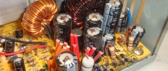
Symptoms of malfunction
Swelling of the capacitors on the motherboard causes the computer to freeze, and the following malfunctions may also occur:
- the system unit does not turn on;
- when you turn on the computer tries to start, but immediately turns off;
- The system unit turns on, but the monitor screen remains dark.
In such a situation, they usually contact a specialized service for repairs. But if the breakdown is caused by swollen capacitors on the motherboard, you can try to repair it yourself.
Minus symbol
The principle of marking the polarity of imported products differs from traditional standards of the domestic industry and consists of an algorithm: “to find out where the plus is, you first need to find where the minus is.” The location of the negative contact is indicated by both special symbols and the color of the housing.
For example, on a black cylindrical body, the negative terminal side, sometimes called the cathode, has a light gray stripe applied along the entire height of the cylinder. A dashed line, or elongated ellipses, or a minus sign, as well as 1 or 2 angle brackets with an acute angle directed towards the cathode, are printed on the strip. The model range with other denominations is distinguished by a blue body and a pale blue stripe on the side of the negative contact.
Other colors are also used for marking, following the general principle: dark body and light stripe. Such markings are never completely erased and therefore you can always confidently determine the polarity of the “electrolyte,” as electrolytic capacitors are called for brevity in radio engineering jargon.
The body of SMD containers, manufactured in the form of a metal aluminum cylinder, remains unpainted and has a natural silver color, and the segment of the round upper end is painted with an intense black, red or blue color and corresponds to the position of the negative terminal. After mounting the element on the surface of the printed circuit board, the partially painted end of the housing, indicating the polarity, is clearly visible on the diagram, since it has a greater height compared to flat elements.
The polarity designation of a cylindrical SMD device corresponding to the marking is applied to the surface of the board: this is a circle with a segment shaded with white lines where the negative contact is located. However, it should be noted that some manufacturers prefer to mark the positive contact of the device in white.
By appearance
If the markings are worn out or unclear, determining the polarity of the capacitor is sometimes possible by analyzing the appearance of the case. In many containers with terminals located on one side and not mounted, the positive leg is longer than the negative leg. Products of the ETO brand, now obsolete, look like 2 cylinders placed on top of each other: a larger diameter and small height, and a smaller diameter, but significantly higher. The contacts are located in the center of the ends of the cylinders. The positive terminal is mounted at the end of a cylinder with a larger diameter.
For some powerful electrolytes, the cathode is located on the body, which is connected by soldering to the chassis of the electrical circuit. Accordingly, the positive terminal is isolated from the housing and located on its upper part.
The polarity of a wide class of foreign, and now domestic, electrolytic capacitors is determined by the light stripe associated with the negative pole of the device. If the polarity of the electrolyte cannot be determined either by the markings or by its appearance, then even then the problem of “how to find out the polarity of a capacitor” is solved by using a universal tester - a multimeter.
Minus symbol
The principle of marking the polarity of imported products differs from traditional standards of the domestic industry and consists of an algorithm: “to find out where the plus is, you first need to find where the minus is.” The location of the negative contact is indicated by both special symbols and the color of the housing.
For example, on a black cylindrical body, the negative terminal side, sometimes called the cathode, has a light gray stripe applied along the entire height of the cylinder. A dashed line, or elongated ellipses, or a minus sign, as well as 1 or 2 angle brackets with an acute angle directed towards the cathode, are printed on the strip. The model range with other denominations is distinguished by a blue body and a pale blue stripe on the side of the negative contact.
Other colors are also used for marking, following the general principle: dark body and light stripe. Such markings are never completely erased and therefore you can always confidently determine the polarity of the “electrolyte,” as electrolytic capacitors are called for brevity in radio engineering jargon.
The body of SMD containers, manufactured in the form of a metal aluminum cylinder, remains unpainted and has a natural silver color, and the segment of the round upper end is painted with an intense black, red or blue color and corresponds to the position of the negative terminal. After mounting the element on the surface of the printed circuit board, the partially painted end of the housing, indicating the polarity, is clearly visible on the diagram, since it has a greater height compared to flat elements.
The polarity designation of a cylindrical SMD device corresponding to the marking is applied to the surface of the board: this is a circle with a segment shaded with white lines where the negative contact is located. However, it should be noted that some manufacturers prefer to mark the positive contact of the device in white.
By appearance
If the markings are worn out or unclear, determining the polarity of the capacitor is sometimes possible by analyzing the appearance of the case. In many containers with terminals located on one side and not mounted, the positive leg is longer than the negative leg. Products of the ETO brand, now obsolete, look like 2 cylinders placed on top of each other: a larger diameter and small height, and a smaller diameter, but significantly higher. The contacts are located in the center of the ends of the cylinders. The positive terminal is mounted at the end of a cylinder with a larger diameter.
For some powerful electrolytes, the cathode is located on the body, which is connected by soldering to the chassis of the electrical circuit. Accordingly, the positive terminal is isolated from the housing and located on its upper part.
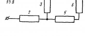
Behavior of a capacitor in DC and AC circuits
In DC circuits, a charged capacitor forms a gap that prevents the flow of current. If voltage is applied to the plates of a discharged part, current will flow. In this case, the capacitor will charge, the current will drop, and the voltage on the plates will increase. When the voltage on the plates and the power supply is equal, the current flow stops.
With constant voltage, the capacitor holds a charge when the power is on. After switching off, the charge is discharged through the loads present in the circuit.
A charged capacitor also does not allow alternating current to pass through. But during one period of the sinusoid, the storage device is charged and discharged twice, so the current is able to flow through the capacitor during its discharge period.
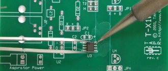
Soldering process
Before soldering, you need to insert the legs into the socket, observing the polarity.
The negative leg of the part is usually shorter than the positive leg; it is installed on the “minus” pad (usually painted white). Soldering must be done from the reverse side; to do this, the board is turned over and the legs are bent. Soldering the capacitor will be much easier if you first moisten the contact “spots” with a drop of flux.
The soldering iron is heated, brought to the contact pad, and the solder wire is brought to it. Use a sting to touch the solder so that a droplet slides onto the soldering site. So you need to solder all the contacts sequentially, and then bite off the extra protruding legs with pliers.
You may not be able to solder beautifully the first time, and you will need to practice. It is better to learn soldering methods in advance on unnecessary parts. After replacing the faulty element, you should try to turn on the motherboard and check its functionality.