Thyristor power regulators are used both in everyday life (in analog soldering stations, electric heating devices, etc.) and in production (for example, to start powerful power plants). In household appliances, as a rule, single-phase regulators are installed; in industrial installations, three-phase ones are more often used.
These devices are electronic circuits that operate on the principle of phase control to control the power in the load (more on this method will be discussed below).
Some nuances of choice
Making a thyristor voltage regulator with your own hands is not difficult. This may be the first craft for a novice radio amateur that can provide temperature control for the soldering iron tip. In addition, soldering irons with the ability to adjust the temperature of factory production are more expensive than simple models without this ability. Therefore, you can familiarize yourself with the basics of soldering and radio design, and also save a considerable amount. With the help of a small number of components you can assemble a simple thyristor with surface mounting.
The mounted type of installation is carried out without the need to use a special printed circuit board. With good skills in this area, you can assemble simple circuits in this way quite quickly.
You can save time and install a ready-made thyristor on the soldering iron. But if you want to understand the circuit completely, then you will have to make the thyristor power regulator yourself.
Important! A device such as a thyristor is a total power regulator. In addition, it is used to adjust the speed of various equipment.
But first of all, you need to understand the general principle of operation of the device and understand its circuit. This will make it possible to correctly calculate the required power for optimal operation of the equipment on which it will perform its direct duties.
Assembling the device
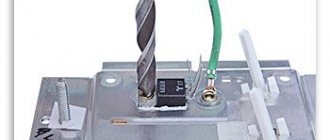
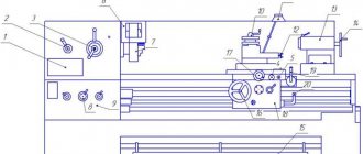
We will not describe all standard assembly actions; we will only note the main points. The transistor must be placed on a heat sink. Why? Because the circuit is linear and at high currents the transistor will get very hot. What is the radiator made of? It can be made from a regular aluminum corner and attached directly to the power supply fan. And, despite the fact that the radiator is quite small in size, thanks to the intense airflow it will cope with its task perfectly.
A transistor is screwed to the radiator through thermal paste; in this circuit it uses a field-effect, N-channel IRFZ44 with a maximum current of 49 A. Since the radiator is isolated from the main board and case, the transistor is screwed directly without insulating spacers.
The stabilizer board is fixed to the same aluminum corner through a brass stand. To regulate the output current, a 5 kOhm variable resistor is used. The wires are secured with plastic ties to prevent them from dangling.
As a result, you should get the following connection diagram for this stabilizer for the charger.
The power supply can be absolutely anything, either a computer power supply or a regular transformer. The cord used to connect to the outlet is a regular computer one.
All is ready. You can now use such an adjustable voltage stabilizer for the charger. It should be noted that the circuit is simple and inexpensive: it simultaneously functions as a stabilizer and a charger.
Design features
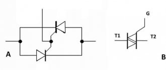
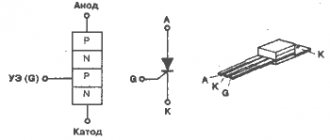
A thyristor is a semiconductor element that can be controlled. It can very quickly conduct current in one direction if necessary. Unlike classical diodes, a thyristor is used to regulate the moment of voltage supply.
It has three elements for outputting current:
- cathode;
- anode;
- controlled electrode.
Such an element will only work if certain conditions are met. Firstly, it must be placed in the circuit under common voltage. Secondly, the necessary short-term impulse must be supplied to the control part of the electrode. This will allow you to adjust the power of the device in the desired direction. It will be possible to turn off the device, turn it on and change operating modes. Unlike a transistor, a thyristor does not require holding a control signal.
It is inappropriate to use a thyristor to provide constant current, since the thyristor can be easily closed if the flow of current into it through the circuit is blocked. And for alternating current in devices such as a thyristor regulator, the use of a thyristor is mandatory, since the circuit is designed in such a way as to fully ensure the necessary closing of the semiconductor element. Any half-wave is capable of completely closing the thyristor section in case of such a need.
The scheme is quite difficult for beginners to understand, but using instructions from experts, they will greatly simplify the creation process.
How to make a current stabilizer for LEDs yourself
Making a stabilizer for LEDs with your own hands is carried out in several ways. It is advisable for a beginner to work with simple circuits.
Driver based
You will need to choose a chip that is difficult to burn out - LM317.
It will act as a stabilizer. The second element is a variable resistor with a resistance of 0.5 kOhm with three terminals and an adjustment knob. Assembly is carried out according to the following algorithm:
- Solder the conductors to the middle and extreme terminals of the resistor.
- Set the multimeter to resistance mode.
- Measure the parameters of the resistor - they should be equal to 500 Ohms.
- Check connections for integrity and assemble the circuit.
The output will be a module with a power of 1.5 A. To increase the current to 10 A, you can add a field switch.
Stabilizer for car lighting
Stabilizer L7812
To operate, you will need a linear device in the form of an L7812 microcircuit, two terminals, a 100n capacitor (1-2 pcs.), textolite material and a heat-shrinkable tube. Manufacturing is carried out step by step:
- Selecting a circuit for L7805 from the datasheet.
- Cut out the required size piece from the PCB.
- Mark the paths by making notches with a screwdriver.
- Solder the elements so that the input is on the left and the output is on the right.
- Make a housing from a thermal tube.
The stabilizing device can withstand up to 1.5 A load and is mounted on a radiator.
Areas and purposes of use
First you need to understand the purposes for which a device such as a thyristor power regulator is used. Power regulators are used in almost all construction and carpentry electric tools. In addition, kitchen appliances cannot be used without them. They allow, for example, to regulate the speed modes of a food processor or blender, the air blowing speed of a hairdryer, and also function to ensure the completion of other equally important tasks. The semiconductor element allows you to more effectively regulate the power of heating devices, that is, their main part.
If you use thyristors in a circuit with a highly inductive load, they may simply not close at the right time, which will lead to equipment failure. Many users have seen or even used devices such as grinders, grinders or drills. You will notice that the power is mainly adjusted by pressing a button. This button is located in a common block with a thyristor power regulator, which changes the engine speed.
Important! A thyristor regulator cannot change speed automatically in asynchronous motors. But in a commutator engine equipped with a special alkaline unit, the adjustment will work correctly and fully.
Operating principle
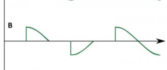
The peculiarity of the work is that in any device the voltage will be regulated by power and interruptions in the electrical network according to sinusoidal laws.
Any total power thyristor can only pass current in one direction. If the thyristor is not turned off, it will continue to work and will turn off only after certain actions have been completed.
When making it yourself, it is necessary to design the structure in such a way that there is enough free space inside to install a control lever or button. In the case when the device is installed according to the classical scheme, it is advisable to connect it through a special switch that will change color at different power levels.
In addition, this addition allows you to partially prevent the occurrence of situations with electric shock to a person. There will be no need to look for a suitable housing, and the device will also have an attractive appearance.
Types of Variable Resistors
Wire
It consists of a tubular plastic or ceramic frame, on which a thin wire with high resistance (manganin or constantan) is laid in the form of a single-layer winding.
A metal slider slides along the surface of the wire, which, when moved, touches the next turn of the winding before leaving the previous one - this ensures smooth adjustment.
To ensure reliable contact between the slider and the conductive layer, the surface of the wire is carefully polished.
Thin film
It consists of a frame in the form of a horseshoe-shaped dielectric plate coated with a thin film made of carbon, boron, metallized or composite materials. A slider, firmly connected to the adjustment mechanism, slides over the surface of the film.
Methods for closing a thyristor
There are many ways to close thyristors. But first of all, it is necessary to remember that applying any signals to the electrode will not be able to close it and extinguish the action. The electrode is only capable of starting the device. There are also analogues - lockable thyristors. But their intended purpose is a little broader than that of conventional switches. The classic thyristor voltage regulator circuit can only be turned off by interrupting the current supply at the anode-cathode level.
There are at least 3 ways to close the power regulator on the Ku202n thyristor. You can simply disconnect the entire circuit from the battery. This will turn off the diode. But if you turn on the device again, it will not turn on, since the thyristor remains in the closed state. It will remain in this position until the corresponding button is pressed.
The second way to close a thyristor is to interrupt the current supply. This can be done by simply shorting the cathode connection of the anode using ordinary wire. You can check it on a circuit with a simple LED instead of a device. If a wire jumper is connected as indicated above, then all the voltage will go through the wire, and the current level that will go to the thyristor will be zero. After taking the wire back, the thyristor will close and the device will turn off. In this case, the device is an LED, and it will go out. If you experiment with such circuits, you can use tweezers as a jumper.
If instead of an LED you install a high-power heating coil, you can get a complete thyristor regulator.
The third method is to reduce the supply voltage to the minimum, and then reverse the polarity. This situation will result in the device turning off.
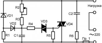
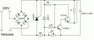
Scheme number 1
There was a stabilized switching power supply that gave an output voltage of 17 volts and a current of 500 milliamps. A periodic change in voltage was required in the range of 11 - 13 volts. And the well-known voltage regulator circuit on one transistor coped with this perfectly. I added only an indication LED and a limiting resistor to it. By the way, the LED here is not only a “firefly” signaling the presence of output voltage. With the correct value of the limiting resistor, even a small change in the output voltage is reflected in the brightness of the LED, which provides additional information about its increase or decrease. The output voltage could be changed from 1.3 to 16 volts.
KT829, a powerful low-frequency silicon compound transistor, was installed on a powerful metal radiator and it seemed that, if necessary, it could easily withstand a heavy load, but a short circuit occurred in the consumer circuit and it burned out. The transistor has a high gain and is used in low-frequency amplifiers - you can really see its place there and not in voltage regulators.
On the left are removed electronic components, on the right are prepared for replacement. The difference in quantity is two items, but in terms of the quality of the circuits, the former and the one that was decided to be collected, it is incomparable. This begs the question: “Is it worth assembling a scheme with limited capabilities when there is a more advanced option “for the same money”, in the literal and figurative sense of this saying?”
Simple voltage regulator
To produce a simple 12-volt system, you will need key elements such as a rectifier, a generator and a battery. The generator is one of the main components. For manufacturing, you will need the above-mentioned radio components, as well as a circuit of a simple power regulator. It is worth noting that it does not contain stabilizers.
For manufacturing it is necessary to prepare the following elements:
- 2 resistors;
- 1 transistor;
- 2 capacitors;
- 4 diodes.
It is better to install a cooling system specifically for the transistor. This will avoid system overloads. It is better to install the device with a good power reserve in order to subsequently charge batteries with a small capacity.
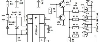
Scheme number 2
The new circuit also has a three-pin electrical connection. component (but this is no longer a transistor) constant and variable resistors, an LED with its own limiter. Only two electrolytic capacitors have been added. Typically, typical diagrams indicate the minimum values of C1 and C2 (C1=0.1 µF and C2=1 µF) which are necessary for stable operation of the stabilizer. In practice, capacitance values range from tens to hundreds of microfarads. The containers should be located as close to the chip as possible. For large capacities, the condition C1>>C2 is required. If the capacitance of the capacitor at the output exceeds the capacitance of the capacitor at the input, then a situation arises in which the output voltage exceeds the input, which leads to damage to the stabilizer microcircuit. To exclude it, install a protective diode VD1.
This scheme has completely different possibilities. Input voltage is from 5 to 40 volts, output voltage is 1.2 - 37 volts. Yes, there is an input-output voltage drop of approximately 3.5 volts, but there are no roses without thorns. But the KR142EN12A microcircuit, called a linear adjustable voltage stabilizer, has good protection against excess load current and short-term protection against short circuits at the output. Its operating temperature is up to + 70 degrees Celsius, works with an external voltage divider. Output load current is up to 1 A during long-term operation and 1.5 A during short-term operation. The maximum permissible power when operating without a heat sink is 1 W, if the microcircuit is installed on a radiator of sufficient size (100 cm2) then P max. = 10 W.