When expanding existing or constructing new openings in load-bearing walls, an apartment redevelopment project may contain various methods of metal reinforcement. Here we will look at such a common option as channel reinforcement.
Channel reinforcement in the form of a U-shaped frame or horizontal lintel is suitable for concrete and brick load-bearing walls.
A frame or lintel made of metal profiles takes on the load that previously fell on the dismantled section of the wall, which allows you to maintain the load-bearing capacity of the wall without reducing it. Thus, strengthening the doorway with a channel helps prevent cracking or even collapse of the wall.
Examples of strengthening openings in concrete walls
An example of strengthening openings in brick walls
How to properly install a channel on a floor
- Types of floors
- Channel for floors
- Calculation of channel bending for floors
- Selection of cross-section and checking for channel rigidity
- How are openings strengthened with channels?
- How is an opening made in a brick wall?
- Insertion methods:
During the construction of residential buildings and other structures, everyone is faced with the need to correctly calculate and install floors. The ceiling is a horizontal structure located inside the building, which divides it vertically into adjacent rooms (floors, attic, etc.). In addition, this structure is load-bearing, since it takes all the loads coming from furniture, people, equipment and the ceiling itself and transfers them either to the walls or to the columns (depending on the type of structure).
Channels as interfloor slabs
Hello! I have a question. I am planning to build a 2-story brick house. Is it possible to use channels instead of a monolithic slab for interfloor slabs? In order to save money.
Marat, Nizhny Novgorod.
Hello, Marat from Nizhny Novgorod!
If you have calculated that the cost of a monolithic (reinforced concrete slab) in the interfloor slab of a two-story house is more expensive than a structure made of channels, then you are in the cards.
Far from widespread, but quite applicable.
The only note. The monolithic slab has support along the entire perimeter of the external walls (and internal partitions), that is, this is quite a decent area. If you are going to use channels, then they will rest only with their ends on sections of these walls and on partitions. The support area will be significantly smaller. This creates significantly larger loads at the support points (in kg/cm2).
To avoid deformation and destruction in the designated areas, it is necessary to use their reinforcement. To do this, you will have to lay reinforced lintels along the top of the walls almost along the entire perimeter, or (which is done much more often) make a continuous armored belt. As an option, a metal beam in the form of a channel or I-beam is laid along the top of two opposite walls of the house, on which the ends of the channels rest.
Construction in Moscow and Moscow region
Wide range of construction services. Foundation, walls, ceilings, roofing, turnkey!
Other questions on the topic of gender:
Construction in Moscow and Moscow region
Wide range of construction services. Foundation, walls, ceilings, roofing, turnkey!
Construction in Moscow and Moscow region
Wide range of construction services. Foundation, walls, ceilings, roofing, turnkey!
Construction in Moscow and Moscow region
Wide range of construction services. Foundation, walls, ceilings, roofing, turnkey!
Semenych (author of materials)
Our site is regularly updated with interesting and unique materials and articles on the topics of lumber, building materials and works, the author's opinion and knowledge of a real coven with more than 15 years of experience are provided. There is a section - funny stories of shabashniks. If you would like to receive information about this, subscribe to our website's newsletter. We guarantee that your address will not be shared with third parties.
Apartment renovation in Moscow and Moscow region
Wide range of repair work. Professional craftsmen.
Reinforcement with corner profile
Strengthening the doorway in the interior brick partition is carried out using corners. Holes are first drilled in corresponding pairs of profiles. There is no need to cut out wide niches in the wall for corners. It is enough to make grooves in it, into which the profile shelves will completely fit.
First, a groove is cut from one side of the partition. A corner is inserted into it, through the holes of which marks are placed on the wall. After drilling through holes in it, a groove is made on the other side. A second corner is inserted into it. The crossbar elements are secured with fasteners. As with the installation of channels, the profiles are connected with steel jumpers.
If additional reinforcement of the doorway is necessary, its verticals are also framed with corners. They are connected by welding to the crossbar. Steel plates are welded between pairs of corners. Holes are made in them through which anchors will be inserted into the partition.
Sometimes it may be necessary to reinforce an old opening in the wall. In these cases, the window or doorway is bordered by a frame of channels or corners. She will take on part of the load.
The methods for installing the frame are practically no different from the methods described above for installing channel and angle profiles.
When expanding openings in an apartment or creating new ones in load-bearing walls, they must be strengthened. For this, various metal structures can be used. The most common option is channel reinforcement. It involves creating a frame or straight crossbar. This method is used for load-bearing foundations made of concrete or brick.
The created metal structures take on the load that previously applied to the dismantled part of the wall. Reinforcing the doorway with a channel prevents cracks or destruction of the base.
Channel for floors
Let's take a closer look at structures made from channel beams for flooring as a load-bearing base. They are the ones who bear the entire load falling on the floors of the second floor. If U-shaped rolled products are used to install the ceiling, then the following points must be taken into account:
- the channel must be laid vertically, since the moment of resistance of the section in this direction is several times higher than the value of the moment in the opposite direction
- The laying scheme is as follows: from the middle of the ceiling, the profile should be turned in the opposite direction, since the center of gravity of the channel does not belong to its wall
This laying scheme is necessary to compensate for tangential stresses. It should be remembered that ceiling channels are subject to bending stresses.
Technology for strengthening the opening with a channel
When making openings, it is best to use diamond cutting technology. Modern tools allow you to carry out work quietly, cleanly and without damaging the rest of the wall. Using an angle grinder or a jackhammer to dismantle the base can lead to collapse. First, the craftsmen install safety supports, which should temporarily distribute the load.
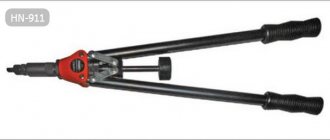
The easiest and most common method of strengthening is a U-shaped channel frame. It is made of vertical shelves and a crossbar. This design is installed along the edges of the opening and secured with special chemical anchor bolts and pieces of reinforcement. Additionally, support heels are fixed to the floor, to which the object is welded with its lower edges. Also, strengthening the opening with a channel means welding at the junction corners of the metal structure parts.
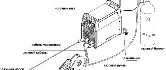
Reliability is ensured by chemical anchors. These are special fasteners that have a capsule with an adhesive base. It is inserted into the prepared hole, where the bolt is then installed. The container breaks, a chemical reaction occurs for some time, after which the fasteners are tightened with a nut. This type of connection can withstand heavy loads. With its help, joint work is ensured to distribute the pressure of the wall and the channel itself. Upon completion of installation, anti-corrosion treatment of the metal structure is carried out.
How to properly install a channel on a floor
During the construction of residential buildings and other structures, everyone is faced with the need to correctly calculate and install floors. The ceiling is a horizontal structure located inside the building, which divides it vertically into adjacent rooms (floors, attic, etc.). In addition, this structure is load-bearing, since it takes all the loads coming from furniture, people, equipment and the ceiling itself and transfers them either to the walls or to the columns (depending on the type of structure).
Numbers, letters and GOSTs
According to the production method, the channel can be bent or hot-rolled. It is easy to distinguish them even for a non-specialist - a hot-rolled channel has a clearly defined edge, while a bent channel it will be somewhat rounded. Other features of various types of channel are determined by their markings.
In particular, the letters A, B and C in relation to batches of hot-rolled channels will indicate that the rolling was carried out with high (A), increased (B) or normal accuracy (C).
The channel number indicates the height of its section, expressed in centimeters.
The width of the profile corresponds to the width of the shelf and can range from 32 to 115 mm. The marking of a channel, for example 10P, reflects its height and type of profile. The height of the channel section is generally the main parameter in its marking. The channel number is its height in centimeters, and the letters adjacent to it indicate that the channel cross-section can be:
1) with a slope of edges (series U and C), where U is the slope, and C or Sb are special series. 2) with parallel edges (P, E and L series), where E means economical series, and L means light. Letters C (for example - 18С, 20С, etc.) can be found in products intended for the automotive industry or for the construction of railway cars (GOST 5267.1-90). Sometimes there are also exotic types of channels. For example, GOST 21026-75 determines the parameters of channels with a bent flange (they are used in the production of trolleys for mines and mines).
The most popular channel sizes
The most popular among consumers are channels with numbers from 8 to 20. Their geometric parameters in categories P (that is, with parallel edges) and series Y (with a slope of internal edges) are the same, the difference is observed only in the radii of curvature and the angles of inclination of the shelves.
It is mainly used to strengthen structures inside domestic and industrial buildings. In its production, semi-quiet (3PS) and mild (3SP) carbon steels are used, which are characterized by excellent weldability.
widely used in mechanical engineering, machine tool manufacturing and other areas of industry. It is also successfully used in the construction of bridges, walls and load-bearing supports in the construction of industrial buildings.
is very similar to the “eight” channel, but has higher strength characteristics and load-bearing capacity, which makes it possible to reduce the metal consumption of structures erected with its participation.
- one of the most popular types of channels. used in building structures for rigid reinforcement of load-bearing parts, giving metal structures special strength and rigidity. Channel 14 comes in standard and increased accuracy.
Channel 20 acts as a load-bearing element when reinforcing bridges, when reinforcing floors (including complex ones) of multi-storey buildings, and in roof purlins.
Due to its high performance qualities, the “twenty” is often used in structures with high loads - both dynamic and static.
Areas of application of the channel, deflection calculations, characteristics
23.10.2018
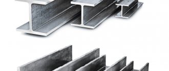
A channel is a type of shaped metal product produced by hot rolling or bending and has a U-shaped cross section. Mass hot-rolled products are made from ordinary quality steel (3 ps/3sp) or low-alloy grades.
Products made from low-alloy steels (most often 09G2S) are designed for operation at low temperatures.
The initial workpiece for the production of bent channel is a strip, the materials are “black” and corrosion-resistant steels, aluminum and its alloys, copper and alloys based on it (bronze, brass).
Profile products made of aluminum and its derivatives can be manufactured by hot pressing without or with further heat treatment (annealing, hardening with natural or artificial aging). The most widely used steel is hot-rolled and bent channel.
Hot rolled steel channel: standards, range, characteristics
The range of these products is determined by GOST 8240-89. The profile size is characterized by a number that is equal (approximately) to the height of the wall, taken in centimeters. In accordance with the standard, the following products are produced:
- With a slope of the inner edges of the shelves. The marking contains the letter “U” after the number. The standard provides for the production of products with a wall height of 50-400 mm, a shelf width of 32-115 mm, a wall thickness of 4.4-8.0 mm, and a shelf thickness of 7.0-13.5 mm. If the designation contains the letter “a” between the profile number and the letter “U,” this means that the product has an increased width and thickness of the shelves. The main area of application of this type of channel is construction. Due to some thickening in the inner corners, the profile has increased strength characteristics. Such metal products are used in frame construction, for the installation of floors, the construction of trusses, stairs, small architectural forms, and metal structures for various purposes.
- With parallel inner edges of shelves. The marking indicates the letter “P” after the number. The index “a” indicates the presence of reinforced shelves. In accordance with the standard, the wall height of products is in the range of 50-400 mm, shelf width - 32-115 mm, wall thickness - 4.4-8.0 mm, shelf thickness - 7.0-13.5 mm. This type of channel has areas of use similar to products with sloped internal edges of shelves. A profile with parallel internal edges is effective in cases where the interface with other parts of the structure occurs along the internal surface of the product.
Table of geometric characteristics of hot-rolled channel
| Channel number | Profile height, cm | Shelf width, mm | Wall thickness, mm | Shelf thickness, mm | Weight 1 m, kg |
| With a slope of the internal edges of the shelves | |||||
| 5U | 5 | 32 | 4,4 | 7,0 | 4,84 |
| 6.5U | 6,5 | 36 | 4,4 | 7,2 | 5,9 |
| 8U | 8 | 40 | 4,5 | 7,4 | 7,05 |
| 10U | 10 | 46 | 4,5 | 7,6 | 8,59 |
| 12U | 12 | 52 | 4,8 | 7,8 | 10,4 |
| 14U | 14 | 58 | 4,9 | 8,1 | 12,3 |
| 16U | 16 | 64 | 5,0 | 8,4 | 14,2 |
| 16аУ | 16 | 68 | 5,0 | 9,0 | 15,3 |
| 18U | 18 | 70 | 5,1 | 8,7 | 16,3 |
| 18аУ | 18 | 74 | 5,1 | 9,3 | 17,4 |
| 20U | 20 | 76 | 5,2 | 9,0 | 18,4 |
| 22U | 22 | 82 | 5,4 | 9,5 | 21,0 |
| 24U | 24 | 90 | 5,6 | 10,0 | 24,0 |
| 27U | 27 | 95 | 6,0 | 10,5 | 27,7 |
| 30U | 30 | 100 | 6,5 | 11,0 | 31,8 |
| 33U | 33 | 105 | 7,0 | 11,7 | 36,5 |
| 36U | 36 | 110 | 7,5 | 12,6 | 41,9 |
| 40U | 40 | 115 | 8,0 | 13,5 | 48,3 |
| With parallel edges of shelves | |||||
| 5P | 5 | 32 | 4,4 | 7,0 | 4,84 |
| 6.5P | 6,5 | 36 | 4,4 | 7,2 | 5,9 |
| 8P | 8 | 40 | 4,5 | 7,4 | 7,5 |
| 10P | 10 | 46 | 4,5 | 7,6 | 8,59 |
| 12P | 12 | 52 | 4,8 | 7,8 | 10,4 |
| 14P | 14 | 58 | 4,9 | 8,1 | 12,3 |
| 16P | 16 | 64 | 5,0 | 8,4 | 14,2 |
| 16aP | 16 | 68 | 5,0 | 9,0 | 15,3 |
| 18P | 18 | 70 | 5,1 | 8,7 | 16,3 |
| 18aP | 18 | 74 | 5,1 | 9,3 | 17,4 |
| 20P | 20 | 76 | 5,2 | 9,0 | 18,4 |
| 22P | 22 | 82 | 5,4 | 9,5 | 21,0 |
| 24P | 24 | 90 | 5,6 | 10,0 | 24,0 |
| 27P | 27 | 95 | 6,0 | 10,5 | 27,7 |
| 30P | 30 | 100 | 6,5 | 11,0 | 31,8 |
| 33P | 33 | 105 | 7,0 | 11,7 | 36,5 |
| 36P | 36 | 110 | 7,5 | 12,6 | 41,9 |
| 40P | 40 | 115 | 8,0 | 13,5 | 48,3 |
Calculation of the table weight of the channel is carried out using the average value of the density of various steel grades - 7.85 g/cm3.
Bent steel channel: GOST, assortment, technical characteristics
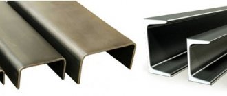
The starting material for the production of bent profiles is hot- or cold-rolled steel strip. The manufacturing process takes place on profile bending units. A bent metal profile can be distinguished from a hot-rolled one by its rounded outer corners and the same thickness of the wall and shelves, which does not exceed 8 mm. Bending eliminates some surface defects.
Unlike hot-rolled metal products, which are produced only as equal flanges, bent metal products are produced both as equal and unequal flanges. The range of equal flange products is determined by GOST 8278-83, unequal flange products - by GOST 8281-80. Their range is much wider than the list of hot-rolled U-shaped products.
The height of the wall of the equal-flange profile is 25-410 mm, the width of the shelf is 26-65 mm, the wall thickness is 2-8 mm.
Due to the strength, which is inferior to the similar characteristics of hot-rolled metal products, various brands of bent channel are used as additional reinforcing elements in metal structures, during finishing work, and reconstruction of dilapidated buildings, in which the low mass of metal plays a decisive role.
Calculation of channel for loads
Rolled steel with a U-shaped cross section is a popular type of rolled metal in demand in construction.
When using a channel to create floors and other critical building structures, calculations for bending and deflection are made using formulas, tables, and online calculators.
To simplify calculations, the operating conditions of profile products lead to standard diagrams. The main ones:
- The channel works as a single-span hinged-supported beam, which is affected by a distributed load; this type of calculation is used when using rolled metal in interfloor slabs.
- Cantilever beam, rigidly fixed at one end, the load is evenly distributed. This pattern is typical for canopies made by welding rolled steel on one side to outlets from a vertical enclosing structure.
- A simply supported beam with two supports and a cantilever. This option is used in the case of organizing a span with the release of rolled metal beyond the wall to support the balcony slab.
- A single-span beam with a hinged support, which is subject to one or two concentrated forces. This scheme is used to calculate the load-bearing capacity of a channel that acts as a lintel on which one or two floor beams rest.
For the online calculator, in addition to the calculation diagram, you will need: span length, design and standard load, design resistance, channel type (the calculator will determine its area independently). The result is strength calculations.
When purchasing a channel, your manager will help you make calculations for the correct selection of rolled metal.
Types of channels
A channel is a type of metal profile with a U-shaped section (50-400 mm high, with a wall thickness of 4-15 mm and a shelf width of 32 to 115 mm). Steel channels are produced mainly by hot rolling of billets on section mills, as well as by cold or hot rolling of coiled steel on roll forming mills. The channel is designed to impart rigidity and stability to the structure in which it is used. It works well in bending and absorbs axial loads.
Channels (GOST 8240-89) are divided into:
- channel with a slope of the inner edges of the shelves (the letter U is placed).
- channel with parallel edges of the shelves (put the letter P).
Good day everyone. It is necessary to make an interfloor ceiling in a rectangular opening between the walls 4x6m. For reasons of lowest cost, the supporting structure is planned to be made of channel bars. Laying on the edge. The channels will be laid in one direction, across the opening. The 15 cm ends will be inserted into the walls and covered with mortar. On top there is a sheathing made of timber, across the channel. There are also two layers of chipboard on top, spaced apart. The load on the floor is normal - a living space and two light plasterboard partitions. Partitions in the letter T.
Which channel should I use and with what pitch should I lay it?
What load can the channel withstand?
A channel is a very popular product made of metal today. Its main distinguishing property is its U-shaped cross-section. The thickness of the finished product can be from 0.4 to 1.5 cm, and the height of the walls can be 5-40 cm.
Thin flange products are manufactured by processing flexible strip using special profile mills. Channels made from non-ferrous metals are obtained after processing the workpiece by pressing and extrusion, and steel channels are obtained using the technology of hot rolling of a metal billet on section mills.
What load can the channel withstand?
A channel is a rolled metal product that is actively used in construction. Moreover, it is quite difficult (almost impossible) to determine a specific area of construction.
After all, the channel is used in the construction of almost any structure. However, the channel is made in various configurations from various alloys.
This means that the load-bearing capacity of channel variations is not the same.
Buying a channel in Rostov will not be too difficult. You just need to clearly understand the characteristics of the channel before purchasing. You will learn how to calculate the load-bearing capacities of structural metal products from the publication below.
Perception of mechanical loads
The main task of the channel is precisely the perception and distribution of mechanical loads in building structures of various types. In other words, the channel will bend under load in any case.
However, there is an acceptable bend and a critical one. When the channel bends critically, its plastic deformation begins, and then the destruction of the product in principle.
The bending of a channel is directly affected by its geometric size.
The following are the characteristics of structural metal products, which are, in principle, used to perform load-bearing capacity calculations:
- standard load;
- channel type (shelf configuration, special purpose, lightweight, etc.);
- channel span length;
- the number of channels laid next to each other;
- elastic modulus (this characteristic naturally applies to steel);
- standard size with maximum vertical deflection.
The calculation is carried out mathematically. Sopromat offers several dependencies that allow you to determine with a high degree of accuracy the load-bearing characteristics of a channel (regardless of the type and configuration).
Maximum permissible deflection: the most important characteristic of a channel
When choosing a structural material and approving it for use in construction, various calculation data are used: minimum moment of resistance, bending moment, normal stress, etc.
However, the most important characteristic is the maximum permissible deflection. It is calculated as follows: the coefficient 5/384 is multiplied by the fraction. The numerator of the fraction contains the product of the design load and ¼ of the length of the channel span. The denominator is the product of the moment of inertia and the longitudinal elasticity index of the material from which the channel is made (its modulus).
The results obtained are a comprehensive calculation that allows you to find out whether the channel is really suitable for use in a particular part of the structure.
What load can channel 10 withstand?
The channel is considered the most common rolled metal product. This is a metal blank in the form of a beam, which has the shape of the letter “P”. The main useful functions of the channel include increasing the stability and rigidity of various structures, which allows the latter to withstand high loads.
The product is manufactured by hot deformation of metal on a rolling mill without the subsequent use of additional heat treatment. All norms for the production of 10P channel are specified in the norms of the GOST 8240-97 standard.
Channel 10 technical specifications
Each GOST standard specifies the technical characteristics of a 10P channel depending on the type and method of its manufacture. But the main ones include the width and length of the workpiece.
The standard length of channel 10 varies from 4m to 12m, but there are also non-standard sizes with a length of 13m. In this case, metal rolling companies produce the product to order. After the length of the rolled product, its marking is indicated - the index “P”, which means the presence of parallel edges in the metal product. The width of the channel between the shelves indicates its number in the assortment.
When producing the product, ordinary steel grades PS 3 or SP 3 are used, low-alloy steel - 09g2s, which increases the strength and reliability of the workpiece, since the steel contains a manganese alloy. You can usually distinguish a hot-rolled billet from a cold-rolled one by its appearance: a hot-rolled channel has a slightly rounded outer corner. The weight of one meter of the product is 8.59 kg.
What load can a 10 channel channel withstand?
Thanks to its technical characteristics and design, the product is able to withstand axial loads and is very resistant to bending loads. The small thickness of the channel serves, as a rule, for the construction of floors on a small shoulder and the creation of crossover structures of medium length.
Channels are used to make supports for high-voltage power lines, cranes, oil rigs and other structures. Also, such samples often find application in machine tool building, mechanical engineering and carriage building.
The wide spread of 10P channel in industrial production has been facilitated by its high strength and reliability characteristics, as well as its affordable price.
Channels come in different sizes and therefore for each type of work it is necessary to select special rolled metal. And for this you need to know what load you can count on it. The channel load is calculated based on what type of beam it is and where the load goes. It is more convenient to make the calculation by presenting a diagram of the beam.
Types of loads and channels
Type A. This type includes beams with rigid embeddings. The load is usually applied evenly . These could be canopies over entrances. Welding is used for their manufacture. They are made of two channels attached to the wall, and the space is filled with reinforced concrete.
Type B. This type includes single-span beams, the load is distributed evenly. Usually these are beams of interfloor floors.
View C. These are simply supported beams. They have two supports with a console, the load is distributed evenly between them. These are floor beams, usually they extend beyond the outer walls. This is necessary to create support for the balcony slabs.
View .E These are single-span simply supported beams where one force is concentrated. Usually these are lintels on which the floor beams rest.
View F. These are cantilever beams where one force is concentrated. This could be a canopy over the entrance or entrance to the house. Only in this case, metal sheets are laid between the channels, and a brick wall is placed on top of them.
The usual way to calculate the load on a channel
To make the calculation you need to do the following:
- First, collect the entire load that will be directed to the beam - normative and calculated, and at the same time already multiplied by the safety factor for the loads.
- The result obtained must be multiplied by the pitch of the beams (in this case this applies to channels).
- Next, you need to calculate the maximum bending moment. The formula is as follows: M max will be equal to the design load multiplied by the length of the channel (but squared) unit of measurement kNm.
- Then proceed to calculate the required moment of resistance of the beam. The formula is as follows: Wtr will be equal to Mmax, which is multiplied by the operating conditions coefficients and everything must be divided by the product 1c equal to 1.12 (this is a coefficient for taking into account plastic deformations).
This will give you the required section cm cubic. In this case, it is necessary to assume that the channel number is greater than the required section moment. All data is taken according to GOST.
Floor installation
In order for a building to last for a long time, beam floors must meet a high level of strength. Have good sound and heat insulation, as well as good ventilation.
When installing wooden beams, the lighthouse installation method is most often used. First, the outer beams are installed, and then the intermediate ones. To avoid mistakes during work, use a level. In case of height differences, the beams can be leveled by placing cuttings soaked in bitumen primer under the end ends.
Difference from other I-beams
The column-type I-beam has some differences from any other variations of this product. The main difference lies in the fact that the wall thickness of the columns is much higher than that of other models. Thanks to this, we can say with confidence that the strength and rigidity of this product is much higher. In addition, this significantly expands the scope of its use. However, there is also some disadvantage here. As the thickness of the walls increases, the mass of one column also increases.
For example, an I-beam with a cross section of 30 cm and marked “B” will weigh about 33 kg. But if we take the same section for a column type, then its mass will be about 87 kg (twice as much). One of the distinctive features lies in the fact that the beam faces can be located at different angles. This means that it can be changed for each application, which will further increase the strength and rigidity of the structure on an individual basis.
One of the main differences and advantages of this type of beam is a well-calculated interface. This allows the beams to cope well not only with static loads, but also with dynamic ones. This type of load can arise due to a variety of factors. This feature has led to the fact that column I-beams have been successfully used in areas where there is increased seismic activity.
Preliminary Considerations
The calculator provides calculations of beams for various schemes of their fastening and load. The load of beams can be distributed (“q” in diagrams 3,4,5,9,15, etc.) or concentrated (“P” in diagrams 1,2,6,7,8, etc.)
Read also: Installing a fitting on a pipeline
The fastening of beams can be: a) cantilever with rigid termination of one of the ends (for example, schemes 1,2,3 and others); b) “sealing - sealing”, when both ends of the beam are rigidly clamped (sealed), schemes 6,7,8,9; c) “hinge - hinge” (diagrams 12,13,14,15 and others), with the left hinge being fixed and the right hinge being movable; d) “sealing - hinge”, (diagrams 9,10,11 etc.)
Rigid embedding of the beam prevents the beam from turning and moving in any direction. A fixed hinge allows only rotation of the beam at the point of attachment in the vertical plane. The movable hinge allows the beam to rotate at the point of attachment in a vertical plane and move along its own axis.
These movements are very insignificant and are a consequence of the deformation of the beam under load. The main type of this deformation is its deflection, the magnitude of which, along with the load applied to the beam, also depends on the length of the beam, the dimensions of its cross section and the physical characteristics of the material, in this case, on its modulus of elasticity (“E”). The modulus of elasticity of carbon steel is (2-2.1)10^5 MPa; alloyed (2.1-2.2)10^5 MPa; therefore, the calculator uses an average value of 2.1*10^5 MPa, which is 2142000 kg/cm2.
From the dimensional characteristics of the cross section of the beam, the moment of inertia of the section (“I”) is used to calculate the deflection; the amount of deflection also depends on the position of the beam point being checked relative to the supports. The permissible amount of deflection of beams is determined by their purpose and place in building structures and is regulated by the relevant SNiP; in mild cases it should not exceed 1/120 - 1/250 of the length of the beam.
THEREFORE, IT IS STRONGLY RECOMMENDED TO CHECK THE CALCULATION RESULTS FOR ACCEPTANCE.
In the construction of critical objects and structures, channels are used that have high strength and are able to withstand significant loads, as well as the resulting shear and axial stresses without loss of load-bearing properties. However, situations may arise when the building was erected with errors in the calculations of the expected loads or they were changed during operation, as a result of which the limit of its strength was reached.
This means that further operation of the structure is impossible, since there is a high probability of creating an emergency situation. Therefore, the only way out of this situation without changing the loading conditions will be to strengthen the structure.
Strengthening the channel for deflection and bending
One of the simplest ways to strengthen a channel is to install a support. It will allow you to significantly relieve the load-bearing beam without making significant changes to the finished structure. The connection method must fully correspond to the type of loading: in the case of constant shear force, you can make any connections of parts that can provide high reliability and strength, but in the case of dynamic ones, you should use riveted and bolted connections.
In some situations, installing a support is not possible due to the operating conditions of the facility. Consequently, you will have to increase the cross-section by welding steel plates or angles in the longitudinal direction, or weld another channel so that a symmetrical structure is obtained. Thanks to this, the main load will shift from the point of possible metal rupture and will be distributed evenly over the area of the new shaped beam.
Another way to strengthen the channel is to redistribute the load between the entire structure using structural changes to the frame or its elements. This will reduce the bending stresses that arise and provide the necessary margin of safety. However, you should not forget about carrying out new calculations of the object, as the problem may become more serious.
Strengthening the channel torsion
To strengthen the channel torsion, it is necessary to install a symmetrical structure by welding. It is believed that welds in the corners of the beam can weaken it, since when the metal is heated, it can become deformed, and the overlay metal, especially when installed locally, can take on the load. Therefore, special double-sided welding methods must be used.
The standard method of reinforcement is to weld a second channel parallel to the installed one to ultimately obtain an I-beam or box. Both options are approximately the same in effectiveness, but their implementation is only possible with full access to the entire surface of the steel frame, otherwise it will be necessary to destroy part of the finish, as well as install temporary safety supports.
The second way to increase torsional resistance is to perform concreting.
Why is an I-beam used in construction?
There are various applications for these steel beams in the production of structural steel. Typically, I-beams are used as support systems or in building frames. Typically, I-beams are laid to provide structural support due to steel's strength, durability, and rust resistance.
When used in construction, I-beams require much less other support structures, which helps save cost and time, and also provides greater structural stability. Versatile I-beams can support a wide variety of loads when used horizontally.
Preparation for work and selection of rolled metal
The technological process of strapping is associated with the arrangement of the pile site. The algorithm for preparatory installation work includes:
- Conducting a site survey, marking pile points for drilling.
- Installation of screw columns and leveling the height.
- Pouring concrete mortar into the cavity of screw piles.
To create a single structure after installing the pile elements, there is no need for standing.
The columns are not subject to shrinkage, so you can start tying without delay. For a foundation protruding a meter or more above the ground surface, it is necessary to install an additional grillage or control stiffening rods at a height of 30–50 cm.
A good result is achieved by using black-rolled metal . Hot-rolled strips or I-beams are used for strapping.
For walls with a thickness of 250 mm, you should choose a profile 24P - 30P; for supports with a cross-section of 108 mm, rolled metal 14P is used.
The metal has significant weight. The weight of the prefabricated structure depends on the length of the channel and its weight. Sometimes it is advisable to use lifting construction equipment for installation, which can be difficult in small areas.
Before tying, it is necessary to level the surfaces of the supports . This is the main condition for installing the channel on screw piles.