Screw-cutting lathe 1K62
1K62
The purpose of the 1K62 screw-cutting lathe is external and internal turning, cutting right and left metric, inch, modular and pitch threads, single and multi-start threads with normal and increased pitch, face threads, etc.
Technical characteristics of the machine 1K62
- The largest diameter of the part installed above the frame is 400 mm
- Distance between centers in mm 710, 1000 and 1400
- Spindle bore diameter in mm 47
- Number of spindle speeds 23
- Spindle speed in rpm 12.5-2000
- Number of innings 42
Feeds per 1 revolution in mm:
- Longitudinal 0.07 - 4.16
- Transverse 0.035 - 2.0
Thread pitch:
- Metric in mm 1-192
- inch (number of threads per 1″) 2 - 24
- modular in mm (0.5-48)Pi
Electric motor power 10kW
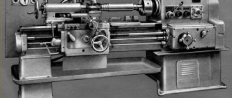
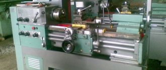
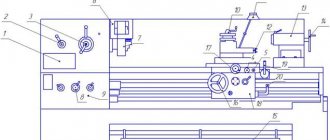
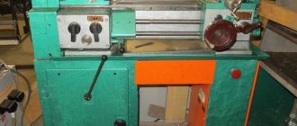
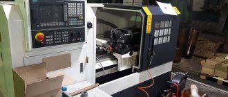
Figure 1 shows a 1K62 screw-cutting lathe. Bed 1, installed on the front 2 and rear 3 stands, carries all the main components of the machine. On the left side of the frame there is a headstock 4. It has a gearbox with a spindle, at the front end of which a chuck 5 is fixed. A tailstock 6 is installed on the right. It can be moved along the guides of the frame and secured depending on the length of the part at the required distance from the headstock. The cutting tool (cutters) is secured in the support holder 7.
Figure 1 — Screw-cutting lathe 1K62
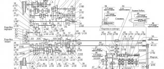
Longitudinal and transverse feed of the caliper is carried out using mechanisms located in the apron 8 and receiving rotation from the running shaft 9 or lead screw 10. The first is used for turning, the second for thread cutting. The amount of caliper feed is set by adjusting the feed box 11. In the lower part of the frame there is a trough 12, where chips are collected and coolant drains. The kinematic diagram of the 1K62 machine is shown in the figure
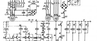
Figure 2 - Kinematic diagram of a 1K62 screw-cutting lathe
Main movement
The main movement in the 1K62 machine is the rotation of the spindle, which it receives from electric motor 1 through a V-belt drive with pulleys 2-3 and a gearbox. A double-sided multi-disc friction clutch 97 is installed on the receiving shaft II. To obtain direct rotation of the spindle, the clutch 97 is shifted to the left and the rotation drive is carried out along the following chain of gears: 4-5 or 6-7, 8-9 or 10-11, or 12-13 , shaft IV, wheels 14-15, spindle V, or through a bust consisting of a group of gears with double-crown blocks 16 - 17 and 18 - 19 and gears 20 and 21. The last pair engages when block 15 - 21 is moved to the right spindle. By switching the wheel blocks, you can get six options for gear engagement when transmitting rotation from shaft IV directly to the spindle, and 24 options when transmitting rotation through an overdrive. In reality, the number of spindle rotation frequency values is less (23), since the gear ratios of some options are numerically the same. The spindle is reversed by moving the coupling 97 to the right. Then the rotation from shaft II to shaft III is transmitted through gears 22 - 23, 24 - 12 and further along the previous chain. The number of gearing options is 15, the actual values of rotation speeds are 12, since the gear ratios of some options are also numerically the same.
Feed movement
The feed mechanism includes four kinematic chains: screw-cutting, longitudinal and transverse feed, and a chain of accelerated movements of the caliper. Rotation of shaft VIII is transmitted from spindle V through gears 25 - 26, and when cutting threads with an increased pitch - from shaft VI through the pitch increasing link and then through gears 27 - 28. In this case, the pitch increasing link can provide four transmission options:
- spindle V, wheels 21 - 20, 29 - 19, 17 - 27 - 28, shaft VIII
- spindle V, wheels 21 - 20, 29 - 19, 16 - 30, 27 - 28, shaft VIII
- spindle V, wheels 21 - 20, 31 - 18, 17 - 27 - 28, shaft VIII
- spindle V, wheels 21 - 20, 31 - 18, 16 - 30, 27 - 28, shaft VIII.
From shaft VIII of the 1K62 screw-cutting lathe, the movement is transmitted through a chain of wheels 32 - 33 or 34 - 35, or through a reversing mechanism with wheels 36 - 37 - 38, replaceable wheels 39 - 40 or 41 - 42 and an intermediate wheel 43 to shaft X. From here, the movement can be transmitted through two options for the engagement of gears. 1. Rotation is transmitted through gears 44 - 45 - 46 to shaft XI, then through wheels 47 - 48 and a ring wheel 49 to the gear cone of the Norton mechanism (wheels 50 - 56) and further along the chain of gears 57 - 58, 59 - 60, 61 - 62 or 63 - 64 through wheels 65 - 66 or 64 - 67 - to the XV shaft. Rotation can then be transmitted to either the lead screw 68 or the lead shaft XVI. In the first case - through clutch 101, in the second - through a pair of 69 - 70 and an overrunning clutch 106. 2. From shaft X through clutch 98, i.e., when the external and internal gears 44 - 71 engage, rotation is transmitted to the Norton cone, which becomes the leading link, and then through wheels 49 - 48 - 47 to shaft XI and further, through coupling 100 to shaft XIII, and from the latter further along the chain of the first option.
Longitudinal and transverse feed of the caliper
To transmit the rotation of the apron mechanism, the running shaft XVI is used. A gear 72 slides along it along the keyway, transmitting rotation from shaft XVI through a pair of gears 73 - 74 and a worm pair 75 - 76 to shaft XVII. To obtain the longitudinal feed of the caliper and its reversal, one of the cam clutches - 102 or 103 is turned on. Then the rotation from shaft XVII is transmitted by gears 77 - 78 - 79 or 80 - 81 to shaft XVIII and then by a pair of 82 - 83 - to rack and pinion wheel 84. Since the rack 85 is fixedly connected to the machine bed, the rack wheel 84, rotating, simultaneously rolls along the rack and pulls the apron with the caliper. Transverse feed and its reversal are carried out by turning on clutches 104 or 105. In this case, through gears 77 - 78 - 86 or 80 - 87
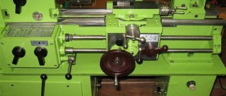
Figure 3 — Gearbox of the 1K62 machine
rotation is transmitted to shaft XIX and then through gears 88-89-90 to screw 91, which imparts movement to the transverse support.
Caliper rapid movement chain
To carry out the accelerated (installation) movement of the caliper, the running shaft XVI is given rapid rotation from the electric motor 92 through the V-belt drive 93-94. In this case, the caliper feed mechanism through the feed box does not need to be turned off, since an overrunning clutch 106 is installed in the drive chain of the drive shaft. Using screw pairs 95 and 96, you can manually move the cutting slide and the tailstock quill. Let's look separately at some components of the 1K62 screw-cutting lathe.
Headstock
Rotation from the main electric motor is transmitted to a driven pulley sitting on shaft I. This shaft carries a reversible friction clutch, from which movement is transmitted to shaft II either through a block z = 56-z = 51, or through a wheel z = 50 and an intermediate block z = 24 — z = 36, sitting on a cantilever axis. From shaft II to shaft III, rotation is transmitted through a triple block z = 47 - z = 55 - z = 38. In the left position of the block z = 43 - z = 52, sitting on the spindle, movement from shaft III is transmitted to the spindle directly through the wheels z = 65 - z = 43, and in the right position of this block - through a bust mounted on shafts IV and V. All shafts rotate on rolling bearings, which are lubricated both by splashing, since the gearbox is filled with oil, and by force - with the help pump The feed movement from spindle VI is transmitted to bit shaft VII and then to the feed mechanism.
Tailstock
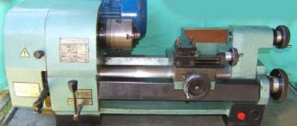
The tailstock 1K62 has a plate 12 and can move along the bed guides. In the hole of the tailstock housing 3 there is a retractable quill 6, which moves using a flywheel 10 and a screw pair 7-8. Handle 5 fixes a certain reach of the quill, and with it
Figure 4 — Tailstock of the 1K62 machine
and the rear center 4. The body 3 of the headstock, using a screw pair 1, can be shifted in the transverse direction relative to the plate 12. With a bolt 14 and a shoe 2, the tailstock can be secured to the bed of the 1K62 machine. This can also be done using handle 9, eccentric 11 and shoe 13. In the conical socket of the quill, you can install not only the rear center, but also a cutting tool for processing holes (drill, countersink, etc.).
Gearbox
The feed box is fixed to the frame below the headstock, has several shafts on which are installed: a stepped block of the Norton mechanism 3, blocks of gears 6 and 13 and switchable clutches 1, 2, 4, 5, 7, 5, 14, 15. On the right In the position of clutch 7, the lead screw 9 rotates, and in its left position (as shown in the figure), the lead shaft 10 rotates through the overrunning clutch 11-12.
Figure 5 — Feed box of the 1K62 machine
Caliper
The support consists of the following main parts: lower slide 1 for longitudinal movement of the support of the screw-cutting lathe 1K62 along the guides 2 of the frame, a transverse carriage 3 and a cutting slide 4. The transverse carriage moves in the guides of the lower slide using a screw 5 and a backlash-free nut 6. When manual when feeding, the screw rotates using handle 7, and with automatic
from gear 8.
Figure 6 — Machine support 1K62
In the circular guides of the transverse carriage 3 there is a rotary plate 9, in the guides of which the cutting slide 4 with a four-position tool holder 10 moves. This design allows you to install and bolt the rotary plate with the cutting slide at any angle to the spindle axis. When the handle is turned counterclockwise, the tool holder 10 is raised by the spring 12 - one of its lower holes comes off the clamp. After fixing the tool holder in the new position, it is clamped by turning the handle in the opposite direction.
Apron mechanism
The apron mechanism is located in a housing screwed to the caliper carriage. Worm wheel 3 rotates from the running shaft through a series of gears. Rotation from shaft 1 is transmitted by the gears of shafts II and III. These shafts are equipped with couplings 2, 11, 4 and 10 with end teeth, which activate the movement of the caliper in one of four directions. The longitudinal movement of the caliper is carried out by a rack wheel 1, and the transverse movement is carried out by a screw rotating from a gear wheel 5. The handle 8 serves to control the uterine nut 7 of the lead screw 6. The shaft with cams 9 blocks the lead screw and the lead shaft of the 1K62 screw-cutting lathe so that it is impossible turn on the caliper feed from them simultaneously.
Figure 7 — Apron mechanism of machine 1K62