The construction of greenhouses and sheds, the laying of utilities - all this requires a bent metal profile. But buying pipes bent to order is expensive, and purchasing a ready-made pipe bender is also not a cheap pleasure. So modern craftsmen use devices and self-made mechanisms to create metal arcs of the required radius.
In this article we will consider the following questions:
- Types of homemade pipe benders and their features.
- The design of the simplest device for bending square pipes.
- Design of a three-roll machine for bending round and square pipes.
- Technology for bending pipes using a three-roll homemade pipe bender.
Types of pipe bending devices and mechanisms
Nowadays, you can find examples of pipe bending equipment that have different designs: from relatively simple devices for manual bending to homemade machines with manual or electric drive.
According to their purpose, pipe benders are divided into two types.
The first type is angular (they allow you to give the desired radius to a certain area of the workpiece).
The second type is three-roll pipe benders - machines and devices that allow you to form a given bending radius along the entire length of the workpiece.
Depending on the method of adjusting the radius, pipe benders are mechanical.
And hydraulic.
The support shaft drive can be either manual or electric.
How to make a rolling machine
The main advantage of this scheme is a smooth increase in load for more precise adjustment of the bending radius. Pressure is smoothly applied to the central roller using a screw, hydraulic or rack jack. The leading ones can be either support or central rollers.
It is possible to use a manual or mechanical drive.
A reliable platform is welded from metal profiles, on which fastenings for the frame can be immediately provided. A frame is welded to the platform - a supporting structure for the central roller and jack. Choose a jack with the smoothest possible stroke of the rod.
If the bending of the pipe is controlled by the position of the outer rollers (and the central one is the leading one), then the supporting structure can be made of wood. However, some parts will still be made of metal:
- roller axes;
- stock;
- fasteners;
- handle for scrolling the rollers.
Next, support rollers are installed on the platform and the drive mechanism is installed. In some cases, an adjustable distance between the stops is provided: through grooves are drilled in the base, the clamps are pressed tightly with bolts and washers.
A simple device for bending metal pipes
The design of a homemade pipe bender depends on the volume and complexity of the work that is planned to be performed with its help. If the device is needed for one-time use (for example, for building a home greenhouse), then there is no need to create a complex three-roll mechanism with hydraulic adjustment of the bend radius.
belor44 FORUMHOUSE user
We urgently need to install a greenhouse. I want an arched one, but neither one based on metals nor my friends have a pipe bender. Build a pipe bender on shafts and rollers? There is neither time nor need for this. I think that a device for manual bending is suitable for one construction.
Yes, indeed, the simpler the pipe bender, the less hassle there is in its manufacture. The main thing is to correctly determine the dimensions of the device, which will directly depend on the bending radius.
We present to your attention a device made by the user moning. It is designed to work exclusively with thin-walled pipes, because bending pipes by hand is hard physical labor.
Moning User FORUMHOUSE
I made this thing for a 30*30 square pipe. The radius that was obtained was approximately 1 meter. You can weld something like spacers or legs on the sides of the device so that it doesn’t throw from side to side when you press on the pipe. Regarding the jumpers at the bottom of the pipe bender: first, the pipe is placed under the top jumper (for the initial bend), then the pipe is placed under the next jumper (for further advancement).
Consistent bending is necessary so that if there is a sharp bend, the pipe does not break.
Calculating the dimensions of the device is very simple: to do this, it is enough to know the bending radius that needs to be obtained on the finished part. The strip (40 mm wide), which serves as a mandrel for the workpiece to be bent, initially has a curvature that provides a given bending radius (R).
Taking into account the presence of elastic deformations, the radius of the mandrel should be slightly smaller than the required bending radius of the workpiece.
According to the author of the invention, the radius of the workpiece is, although not significantly, larger than the radius of the mandrel itself.
Knowing how to use welding, a grinder and auxiliary tools, this device can be made in less than 1 day.
Each metal pipe has its own elastic limit, therefore, the bending radius cannot be reduced below certain values. Permissible minimum radii can be taken from the corresponding tables.
We present an example of a table of permissible radii for round pipes.
Minimum bending radii of pipes in a cold state
| Pipe outer diameter, mm | Bend radius, min | |||
| 45 | 35 | 20 | 10 | |
| R bend, min | ||||
| 18 | 74 | 62 | 56 | 43 |
| 24 | 95 | 79 | 65 | 55 |
| 32 | 115 | 96 | 79 | 67 |
| 38 | 156 | 131 | 107 | 91 |
| 50 | 197 | 165 | 136 | 115 |
| 60 | 238 | 199 | 165 | 139 |
| 75 | 280 | 260 | 194 | 173 |
| 80 | 324 | 270 | 224 | 190 |
| 90 | 362 | 302 | 250 | 213 |
Manufacturing of electromechanical pipe bender
In the design of an electromechanical pipe bender, three main working parts can be distinguished: one pressure and two support (drive) shafts. Hence the name of the machine – three-roll rolling pipe bender.
Such a device has a rather complex design, so if you were unable to get the drawings of a homemade pipe bender, we recommend that you first draw each of its elements on paper (at least as a sketch). And we will tell you step by step what dimensions and characteristics the main components of the future product should have.
So, the main function of a pipe bender is to bend parts to a given bending radius. The bending radius depends on the distance between the support rollers (shafts) and is adjusted by the pressure roller. The distance between the support rollers is a constant value. This is what should be taken into account when starting to design a machine.
Alli58ru FORUMHOUSE user
The distance between the lower rollers depends on the minimum bending radius. When determining it, keep in mind that the smaller the distance between the rollers, the harder it is to lower the pressure roller and the harder it is to pass the workpiece between the shafts. And vice versa: the greater the distance, the easier it is to twist. For me, if memory serves, the distance is about 35-40 cm. The shafts rotate quite easily: I bent a minimum radius of about 50 cm, but less is possible.
The bend radius (arc radius) is calculated using a simple geometric formula.
Guided by it in relation to your equipment, you can quickly adjust the machine to the specified parameters.
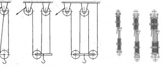
Winding machines
To make a homemade pipe bender that works on the winding principle, a massive metal rotating disk is attached to a fixed frame, to which the pipe is fixed with a clamp or clamp. The pressure roller only allows rotation around its axis. The rotary disk is driven by a jack (hydraulic, electrohydraulic, rack and pinion), the impact of which is transmitted through a rod connected to the template through a lever. The lever rotates freely around the template. To transmit force, clamps are used that are installed in holes around the circumference of the template.
Gearbox-based models have a different design . A hole is drilled in the tabletop through which the rotating template and the output of the gearbox are connected. A handle for independent rotation or an electric motor is installed at the input of the gearbox. The motor/gearbox pair is selected individually in each case. The pressure disk stops are placed next to the template. This design allows you to easily change templates depending on the required bend radius and pipe cross-section. The electric motor speeds up the work process significantly.
As in the previous version, wooden discs can be used for soft metal pipes. In this case, it is not necessary to resort to the use of jacks; the operator’s muscular strength is sufficient for the work. But combining the template and the base will not work here.
Manufacturing of rollers
To make rollers, you should look for reliable materials that have already passed the strength test. Some use rotors from electric motors of old washing machines or kingpins from a KamAZ vehicle, others use carbon steel circles. In fact, there are many options, the main thing is not to forget that the chosen material must be strong enough. User Dva11, for example, used wheel hubs from an old sprinkler installation.
Dva11 FORUMHOUSE user
Hub diameter – 75 mm, length – 110 mm, bearings were selected according to the hub (205 fit). I had to buy 5 bearings and 1 pulley, and made the rest of the parts from scrap metal.
Smooth cylindrical shafts are a universal option. They are used to bend pipes of various sections. If the profile of the shafts is brought into line with the profile of the pipes being bent, the quality of bending will noticeably improve.
You can also use blanks designed for different profiles of bent workpieces.
Ideally, removable nozzles or ring clamps (limiters) are installed on the shafts, with the help of which the profile of the rollers is adjusted to the width of the pipe.
rusi45 FORUMHOUSE user
I made some improvements to the design of the rollers: I made attachments for the pipe on the outer shafts, where the stops are located. Tests were carried out on a 1 inch pipe. The attachments are easy to replace. To do this, I made one side of the bearings sliding. The nozzle is made of steel 65G (plus hardening). There is virtually no wear, and the file does not take hardness.
The internal radius of the roller or nozzle for a round pipe should be made with a margin: the radius of the pipe plus 1-2 mm. For example, if the pipe diameter is 24 mm, then the internal radius of the roller will be 13-14 mm. Only in this case the pipe will not jam during rolling.
This is the size we are talking about.
If a pressure roller designed for bending rectangular pipes has a slight convexity in the middle, this will help maintain the geometry of the profile being bent. The roller will press the upper wall of the pipe inward, preventing the workpiece from spreading out to the sides.
What is a punch
The punch is one of the most important components of a pipe bender. It is also called a shoe. You can make it from any available materials. To make a metal shoe, you need to take a thick-walled steel pipe, slightly larger in size than the profile one, which needs to be bent. The pipe for the punch is cut lengthwise on a milling machine or with a grinder into the required length elements. Then the resulting part is bent and the ends are welded to a metal ring. Next, the punch can be attached to a pipe bender and used for its intended purpose.
Compared to factory punches, homemade shoes have a number of advantages:
- Cheapness of the part;
- Structural strength;
- Long service life;
- Ease of installation and minimal time costs;
- Reliability.
The pipe bender can vary significantly in size.
The metal punch will be more durable and strong, and it is also very easy to make.
Frame design
Having decided on the center distance and the design of the rollers, you can mark the blank parts for the frame. Based on the experience of FORUMHOUSE users, it should be concluded that the strongest frames are made from steel channels (at least 80 mm wide). This material is easy to get, so you can safely take note of it.
The photo shows the machine at the manufacturing stage. And here is the drawing that is taken as a basis.
Person User FORUMHOUSE
During the work, some changes were made to the original drawings.
The presented drawing is not a mandatory guide to action, but provides an objective understanding of how a rolling pipe bending machine works.
Types of methods
A pipe bender for metal-plastic pipes is a basic machine that operates on one mechanics. The machine is indispensable for pipelines, including thick-walled and metal-plastic ones. It can work with different types of metal (steel, aluminum, copper, zinc and their alloys). For greater productivity, the bend areas can be pre-red to release the metal, relieve internal stress and make it softer.
Cold method
Common in garage craftsmanship. If you don’t have a blowtorch or burner, you can use it. The disadvantage is that it requires more effort. Cold metal is harder and can crack. Therefore only suitable for raw steel and soft non-ferrous metals. Safer compared to hot rolling, since you don’t have to work with high temperatures.
Hot method
Requires a torch and blowtorch. Heating relieves stress from the metal and therefore it becomes more pliable, but this is only relevant for thin-walled pipes. Thick-walled tubes cannot be heated to more than 300 degrees in a garage.
Clamping mechanism
Many craftsmen make a clamp from a regular car jack (mechanical or hydraulic). The forces that it is capable of creating are quite sufficient to give the metal workpiece the desired configuration.
greysv FORUMHOUSE user
I used an old gazelle screw jack as a clamping screw. Easily bends two 20x20 tubes.
If a hydraulic jack is used, it must be rated for 2 tons or more. The main advantage of a hydraulic clamp is that it can be operated without much effort. Advantages of a screw jack: it is easier for them to set the bending radius.
Instead of a mechanical jack, homemade screw clamps are often used. They also allow you to bend workpieces exactly according to specified parameters.
moning
Why is a screw worse than a jack? Order a screw with a smaller thread pitch from a turner so that less effort is applied when rotating. This will cost an order of magnitude cheaper than a jack.
An example of creating such a device
Please refer to the following photographs and drawings before starting the production process.
The most important part of the product is the axis. To be more precise, we are talking about the fit and choice of shaft design. If necessary, the clamping screw can be replaced with a jack.
The technology for making a pipe bender with your own hands is as follows:
- Bearings are purchased. The best option is support models that can self-center.
- Two gears are purchased.
- According to the drawings, the required shafts are turned on a lathe.
- If the gears fit the design, they are keyed.
- The locking thread is cut into the stopper.
- Several holes are made in the ring.
- Special grooves are made for the oblong metal part.
- Similar operations are carried out with the unit that fixes the bearings.
- For ease of installation, the channel shelf for the jack can be sawed off.
- The base of the device is welded.
- The legs are attached using a special apparatus.
- The pressure roller is installed.
- The locknut is tightened.
- The base is hung on the spring. The upper stop must be bolted. If necessary, the shaft can be easily dismantled.
- Support rollers are installed at the bottom.
- A special device is made to tension the chain. It is convenient to use a magnetic corner for this.
- The stars are fixed.
- The keys and tensioner are installed.
- The rotation handle is installed.
- The jack is secured to the platform with two welded bolts.
This homemade tool is an indispensable element in everyday life. It should be noted that the quality of the bend is in no way inferior to the factory device.
In order for the product to acquire a marketable appearance and be protected from corrosion, it must be coated with paint or treated with a special solution.
Electric drive
It takes a lot of effort to push a workpiece through a machine using a mechanical handle. Therefore, mechanization of manual labor is a completely justified goal.
A suitable electric motor and a small mechanical gearbox will help you bend pipes “with a cup of coffee in your hands.” These devices are installed on the frame of the pipe bending machine in accordance with the prepared drawings. The drive sprocket mounted on the gearbox shaft can be connected to the support shafts with a metal chain (for example, from the timing belt of a passenger car).
Human
I had a 380V electric hoist lying around in the garage for about 15 years, and I was still thinking about where to use it. It weighs 40 kg and lifts up to 500 kg. A long time ago I bought a small hoist, which, with a weight of 8 kg, lifts the same amount. So: I disassembled it, removed everything unnecessary, after which I got an electric motor and gearbox in one bottle. This item weighs 6–7 kg.
We looked at the main elements of a pipe bending machine, which, if desired and with some ingenuity, can be made independently. At the end of the article, we’ll talk about how to use this equipment correctly so as not to spoil the workpiece.