The post-war rapid growth of industrial production in the USSR required an urgent expansion of the machine park. To prevent the outflow of currency abroad, domestic design bureaus began developing metal-cutting equipment. First, a basic model was produced, which was tested in real conditions. After this, the mechanism was improved. Such a modified unit is the 2N118 vertical drilling machine.
Vertical drilling machine 2N118
Brief information about machine grading
Classification of units:
- Machining of small holes up to 16.0 mm. Most often, such diameters are used in instrument making.
- Processing of medium and large diameters from 18.0 to 75.0 mm.
- Radial drill type for drilling large products.
- Machines for drilling high-precision diameters.
- Milling type.
- Centering machines.
- Multi-spindle machines.
Multi-spindle machine
This is interesting: Do-it-yourself semi-automatic welding inverter: diagram, photo, video
Drilling equipment
It is used in any technological chain, but its main purpose is small-scale and single-piece production. Such machines perform a number of operations:
- thread cutting;
- countersinking;
- drilling;
- trimming ends;
- deployment;
- countersinking.
After reviewing, they can be divided into three large groups depending on the operations performed:
- specialized, perform a limited number of actions;
- universal, make up the main part;
- special, they work without readjustment, according to a given cycle.
Such units can be classified according to the maximum drill diameter used:
- lightweight, drilling up to 12 mm;
- medium, obtaining holes 18-50 mm;
- heavy, drilling 75 mm holes.
The main distinctive features of metal-cutting equipment are the movements made by the cutting tool and devices. In our case, this is the rotation of the drill and the progressive feed of the spindle. All main parameters are included in the machine passport, which is directly included in the operating manual.
In this document you can find instructions for attaching the machine to the workplace. First of all, it must be located strictly horizontally in relation to the foundation. The reliability of all mechanisms depends on this. This is achieved using special levels.
The design of the machine assumes the following types:
- desktop;
- columned;
- radial drilling;
- deep drilling;
- multi-spindle;
- central;
- drilling and milling;
- coordinate drilling;
- radial drilling.
All of them are complex mechanisms, so before starting work, maintenance personnel must carefully read the operating instructions. And while working, adhere to all recommendations.
Characteristic advantages of the machine
Drilling machine 2n118 is designed for drilling small holes up to 18.0 mm in metal surfaces. In order to improve the quality of work, a maximum torque of 880 Nm is developed and the feed is equal to 560 kgf. When working with each part, it is possible to select the speed and feed amount, which makes the work more accurate and efficient, and reduces the risk of defects.
Similar models:
- 2A118 layout and single-spindle head.
- 2N118F2 modernized version with an automated control system.
- 2b118 with an increased number of feeding stages.
- Vertical mechanism 2N118K.
Machine 2N118K
Technical data about the product
Specifications:
- “T” is a shaped working surface and is equal to 32.0 × 36.0 cm.
- The movement of the surface when the flywheel rotates is 2.4 mm, along the vertical plane - 35.0 cm.
- The total weight of the device is 450 kg.
- The distance from the extreme point of the spindle to the working surface is 65.0 cm.
- The machine's reach is 20.0 cm.
- The spindle head can move up to 30.0 cm.
- The working stroke of the sleeve is 15.0 cm.
- The spindle head moves 4.4 mm per revolution.
- The (average) spindle speed is 2.4 rpm, minimum 200 rpm, maximum 2.8 thousand rpm.
- The spindle rotation speed is adjusted according to nine parameters.
- The electric motor shaft power is one and a half kilowatts, the maximum rotation speed is 1.42 rpm.
- The maximum feed rate is 560 kgf.
- Dimensions 87.0x59.0x208.0 cm.
Among the main features is the spindle braking option.
Information about the manufacturer of the vertical drilling machine 2N118
2N118 vertical drilling machine is Molodechno Machine Tool Plant MSZ , founded in 1947.
Since January 1958, the plant became known as the Molodechno Machine Tool Plant, having received the task of specializing in the production of drilling machines. Since 1961, the plant began mass-producing two-spindle, three-spindle, and then universal vertical drilling machines
The machine tool plant, in rather difficult conditions, is trying to maintain its core specialization. According to the results of work for 2004, machine tools amounted to 42% of the total production volume.
Machine tools produced by the Molodechno Machine Tool Plant
- 2A106P
high-precision tabletop drilling machine Ø 6 - 2N106P
high-precision tabletop drilling machine Ø 6 - 2N118
vertical drilling machine Ø 18 - 2N125L
vertical drilling machine with rotary table Ø 25 - 2С108П
high-precision tabletop drilling machine Ø 8 - 2054m
semi-automatic thread-cutting machine for cutting threads with M8 taps - 2056
semi-automatic thread-cutting machine for cutting threads with M18 taps
Topics on 2N118, 2N125L, 2056. Drawings. — Drilling machines
Passport
https://www.chipmaker.ru/files/file/69/ - 2N118 - Universal vertical drilling machine, Molodechno, 1971.
https://www.chipmaker.ru/files/file/6314/ - excerpt from passport 2N118-1
Topics about 2N118
https://www.chipmaker.ru/topic/107698/ — Cams on the 2N118 dial 03/31/2013
https://www.chipmaker.ru/topic/84295/ — Drill bit 2N118, for threading 04/23/2012
https://www.chipmaker.ru/topic/65571/ - Restoration of 2N118-1 07/12/2011
https://www.chipmaker.ru/topic/77488/ — Modernization of the 2N118-1 feedbox 01/21/2012
https://www.chipmaker.ru/topic/75252/ - 2n118 - is more possible? 11/19/2011
https://www.chipmaker.ru/topic/56587/ - 2N118: repair and restoration 02/17/2011
https://www.chipmaker.ru/topic/57877/ — Tell me the 2N118 drive diagram 03/06/2011
Topics that mention 2N118
https://www.chipmaker.ru/topic/115003/ — Automatic thread-cutting machine 2056 — restoration. Need advice! 08/04/2013
https://www.chipmaker.ru/topic/110686/ — Feedbox 2N125L. Message #4. 05/16/2013
https://www.chipmaker.ru/topic/109335/ - Saved the 2N125, now I’m fixing it. Have questions. Message #57. 04/23/2013
https://www.chipmaker.ru/topic/102341/ — Repair of two 2N125L. Message #18. 01/26/2013
https://www.chipmaker.ru/topic/105194/ — Were there drilling machines in the USSR larger than 2M112, but smaller than 2N125? 02/27/2013
https://www.chipmaker.ru/topic/101200 - Drilling 2B118. 01/13/2013
https://www.chipmaker.ru/topic/98256 - Reduced speed for 2M112. 01.12.2012
https://www.chipmaker.ru/topic/94063 - M112nd second-second. 10/05/2012
https://www.chipmaker.ru/topic/49754/ - Drilling 2H125. Message #46. 01.12.2010
https://www.chipmaker.ru/topic/84596/ — What to choose 2N125 or 2G125. 04/27/2012
https://www.chipmaker.ru/topic/26777/ — Owners of machine 2118A, respond! 08.12.2009
https://www.chipmaker.ru/topic/22158/ — They gave me a drill as a gift. 09/12/2009
www.chipmaker.ru
Equipment controls
There are a number of elements of the unit:
- Automatic power switch.
- Toggle switch for work surface lighting.
- Cooling system fluid pump switch.
- Handle for adjusting feeds.
- Button to activate feed.
- Regulator for selecting feed speeds.
- Control unit and direction of spindle movement.
- Drilling head rotation speed regulator.
- Bolts – clamps of the wedge of the working head.
- Handle for fixing the work table clamp.
- Electrical contacts and network power board.
- To provide auxiliary control, a number of buttons, an automatic starter, and a manual starter are used.
This is interesting: Do-it-yourself collet chuck: components and manufacturing procedure
Electrical protection
To prevent unwanted overloads, the manufacturer provides protection - automatic switch AST - 3. Grounding of the machine is provided by a coil of magnetic starters. The drill bit, as well as the contact board, must be connected in accordance with the requirements and regulations that apply to production equipment.
Electrical components: electric power unit, electric pump for supplying liquid to the cooling system, start-up and automatic shutdown mechanisms, rectifiers, local lighting to improve the work process.
It is imperative that every employee, especially those who work at a machine, must strictly comply with the norms and requirements of the labor protection instructions. Otherwise, the worker is not allowed to enter the workplace.
2Universal single-spindle vertical drilling machine. Purpose and scope
The vertical drilling machine model 2N118 with a nominal drilling diameter of 18 mm is designed to perform the following operations: drilling, reaming, threading and trimming ends with knives.
2N118 drilling machine is designed for operation in main production shops, as well as in conditions of single and small-scale production in tool, experimental, mechanical repair and tool shops with individual and small-scale production.
2N118 machine , assigned to a nominal drilling diameter of 18 mm, allows processing of parts with a feed force of up to 560 kg and a torque of up to 880 kg-cm.
Operating principle and design features of the machine
2N118 machine belongs to the design range of medium-sized vertical drilling machines (2N118, 2N125, 2N125L, 2N135, 2N150, 2G175) with a nominal drilling diameter of 18, 25, 35, 50 and 75 mm, respectively. Compared to previously produced machines (with index A), the new range of machines have a more convenient location of the gearbox and feed control handles, better appearance, simpler technology for assembling and machining a number of critical parts, and a more advanced lubrication system. The aggregate layout and the ability to automate the cycle ensure the creation of special machines based on them.
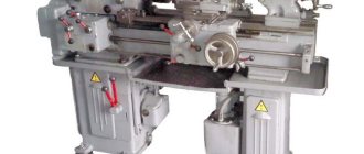
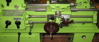
General view of the most common universal single-spindle vertical drilling machine 2N118
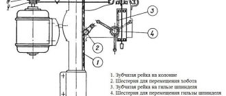
A box-shaped column is mounted on the foundation slab. In its upper part there is a spindle head that carries an electric motor and a spindle with a tool. A spindle head is installed on the vertical guides of the column, inside of which there is a feed mechanism that carries out the vertical movement of the spindle. The spindle can be raised and lowered mechanically or manually using the steering wheel. There is a table for installing and securing the device with the workpieces being processed. It can be installed at different heights, depending on the size of the workpiece.
Main technical characteristics of the tabletop drilling machine 2n118
Manufacturer: Molodechno Machine Tool Plant MSZ.
The main dimensions of the machine correspond to GOST 1227-79.
- Maximum drilling diameter: Ø 18 mm
- Maximum drilling depth: 300 mm
- Maximum height of the workpiece installed on the work table: 500 mm
- Spindle speed limits per minute - (9 steps) 180..2800 rpm
- Spindle end - Morse 6
- Electric motor power: 1.5 kW
- Machine weight: 670 kg
Modifications of the drilling machine 2N118
2A118 - universal single-spindle vertical drilling machine
2N118K - coordinate vertical drilling machine
2N118F2 - CNC vertical drilling machine
Analogues of the drilling machine 2N118
МН18Н - Ø18 - manufacturer Molodechno Machine Tool Plant MSZ, RUP
2T118 - Ø18 - manufacturer Gomel Machine Unit Plant, RUP
Archive for machines
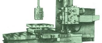
The universal horizontal boring machine 2A614-1 is designed for processing body parts with precise holes. interconnected by exact interaxal distances.
The largest mass of processed parts is 2000 kg.
The 2A614-1 machine, unlike the 2A615-1 machine, is equipped with a built-in faceplate with a radial support.
The machines have great versatility. They can be used for drilling, boring, countersinking and reaming holes, milling planes and grooves, as well as turning ends, boring holes and processing annular grooves with a radial support of the faceplate.
- The 2A614-1 machine, upon customer request, can be manufactured with a thread-cutting device.
- The presence of a mechanized tool clamp, rigidity, vibration resistance, speed and ease of control of the machine make it possible to carry out precise productive processing on them with the least amount of machine and auxiliary time.
- The machines are designed for use in tool and machine shops.
Technical characteristics of horizontal boring machine 2A614-1
Technical characteristics of machines are the main indicator of the suitability of a machine for performing certain jobs on machines. For horizontal boring machines, the main characteristics are:
- Table work surface size
- Retractable spindle diameter
- Maximum longitudinal movement of the spindle
- Spindle revolutions per minute
Below is a table with the technical characteristics of the 2A614-1 jig boring machine. More detailed technical characteristics of the machine can be found in the passport of the machine 2A614-1 located below.
| Name of parameters | Unit. | Quantities |
| Machine accuracy class according to GOST 8-77 | N | |
| Retractable spindle diameter | mm | 80 |
| The end of the retractable spindle with a cone for holding the tool | 40AT5, Morse 5 | |
| Built-in turntable dimensions (L x W) | mm | 1000×1000 |
| Vertical movement of spindle head | mm | 800 |
| Longitudinal movement of the retractable spindle | mm | 500 |
| Longitudinal movement of the built-in rotary table | mm | 1000 |
| Lateral movement of the built-in rotary table | mm | 1000 |
| Radial movement of the built-in faceplate support | mm | 125 |
| Retractable spindle speed | rpm | 20…1600 |
| Faceplate rotation speed | rpm | 6,3…200 |
| Feed limits of working bodies | mm/rev | 0,02…8 |
| Feed limits of the retractable spindle, spindle head, table in both directions. | mm/min | 1,26…2000 |
| Feed limits of the built-in faceplate caliper | mm/min | 0,5…800 |
| Speed of fast installation movements of the retractable spindle, headstock, table | mm/min | 5000 |
| Speed of fast installation movements of the built-in faceplate caliper | mm/min | 2000 |
| Maximum permissible torque on the retractable spindle | Nm | 865 |
| Maximum permissible torque on a triple faceplate | Nm | 1300 |
| Maximum permissible spindle feed force | kN | 7,5 |
| Maximum permissible table feed force | kN | 10 |
| The largest mass of the processed product | kg | 2000 |
| Overall dimensions of machines without attachments (LxWxH) | mm | 4518x2590x2585 |
| Weight of machines without electrical equipment and accessories | kg | 8500 |
Description of the machine
A machine-tool plant in the city of Molodechno began producing a vertical drilling machine model 2N118. At the end of the fifties, it was reoriented to the production of drilling units. In the early sixties, production of the basic model 2118 was launched. Based on its operational data, the designers developed a vertical drilling machine 2N118, the technical characteristics of which were improved, and all the shortcomings were taken into account.
The basis of this mechanism is a column, which is attached to the foundation with its base. It is equipped with a gearbox located in the upper part of the structure, as well as a table and feedbox in the spindle headstock. Design features include rigidity, strength of mechanisms and speed range of the cutting tool. The movement of the working head along the bed occurs thanks to a rack and pinion mechanism controlled by a steering wheel.
The part is installed on the table, in special devices, and can be moved along it to align the hole drilling site with the cutting tool. The table can move along the bed. Its installation, as well as the installation of the spindle head, depends on the height of the tool and the part. The processing process can take place in manual and mechanical modes.
To understand how the 2N118 drilling machine works, open the passport and find all the necessary information.
Download the passport (operating instructions) of the 2N118 machine
Let us highlight the main technical characteristics from it:
| Parameter | Meaning |
| Dimensions, mm | 870x590x2080 |
| Weight, kg | 450 |
| Max diameter, mm | 18 |
| Table: | |
| Dimensions, mm | 360x320 |
| Displacement, mm | 350 |
| Spindle: | |
| Rotation, rpm | 180-2800 |
| Displacement, mm | 300 |
| Cone | Morse 2 |
| Speed | 9 |
| Motor, W | 1500 |
In addition, here you can find the kinematic diagram, which is given below, and a description of its features.
Kinematic diagram of the machine
These include:
- electric reverse, changing the direction of rotation of the head;
- 9-speed gearbox, expanding the rotation range of the cutting tool;
- 6-speed gearbox that regulates vertical movement;
- rack and pinion mechanism moving the spindle head;
- a screw pair that allows the table to move.
For long-term operation, it is necessary to pay attention to securing the 2N118 machine to the foundation. Using a level, it is placed on the wedges, after which the solution is poured under the base. Once it hardens, the foundation bolts are tightened.
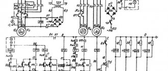
Electrical circuit of the machine 2N118
You cannot bypass the electrical part of the machine. Its main components are:
- motor that rotates the spindle;
- selenium rectifier;
- automation, consisting mainly of relays and starters;
- cooling pump.
The rectifier is used to activate the brake starter, thereby dynamically braking the cutting tool. In addition, the electric motor is protected from overload by a circuit breaker.
To avoid accidents and injuries to operating personnel, all equipment is properly grounded.
All of the above documents for 2N118 are included in the instruction manual. It makes it possible to correctly install, start and operate the mechanism. And in the event of a breakdown, quickly identify the problem.
Equipment classification
A system of symbols has been adopted, which makes it easy to understand the marking of units. Difficulty in deciphering the name of the machine arises in specialized production, when the abbreviation is set by the manufacturer. In the standard case, numbering is based on the decimal system.
The equipment designation includes four numbers and several letters, the latter can be located anywhere. The letters can indicate the degree of automation, accuracy class or new modification. Let's look at the meaning of the numbers:
- It defines a group of machines, depending on the technological operation being performed. There are nine groups in total.
- Indicates the type of equipment, there are nine of them.
- The last numbers show the main size of the unit.
In our case, the first number (2) indicates the drilling group. The second number (1) indicates the vertical drilling type of the machine. Using the last numbers, we determine the maximum size of the hole that the mechanism can drill. The letter (n) indicates a new modification of the base model.
Equipment design
Description: the main element is a box-shaped column - the headstock. It is installed on a metal plate - the base. The headstock moves sideways along the rack and pinion mechanism using an electric motor drive.
An electric motor is located on the front upper part. At the bottom there is a spindle assembly with a rotation head. The inner part is filled with a gearbox, which is responsible for the rotation speed, feed rate, and vertical lift. Vertical ascent and descent is provided by a special rack and pinion mechanism. And this organ is activated - the steering wheel.
The workpiece is mounted on the work table, moved if necessary, and the height is adjusted. Adjustable with a special handle on the side.
The kinematic diagram of the machine operates in the following order:
- The gearbox regulates the supply of one of nine speeds.
- Using a reversible electric motor drive, you can change the direction of rotation.
- This function is especially important when you need to cut internal threads on parts.
- The spindle is fed vertically by a rack and a gear shaft, which is installed in the lower front part of the spindle head.
- The side handle is responsible for moving the spindle head along the column guides.
- The work table moves vertically due to the rotation of the handle.
Device diagram
Technical characteristics of the machine 2N118
| Parameter name | 2N118 | 2B118 |
| Basic machine parameters | ||
| The largest nominal drilling diameter in steel σ = 50..60 kg*mm 2 , mm | 18 | 18 |
| The smallest and largest distance from the end of the spindle to the table, mm | 0…650 | 50..650 |
| The smallest and largest distance from the end of the spindle to the foundation plate, mm | 800..1150 | |
| Distance from the axis of the vertical spindle to the rack guides (overhang), mm | 200 | 200 |
| Desktop | ||
| Dimensions of the working surface of the table (length x width), mm | 320 x 360 | 320 x 400 |
| Number of T-slots Dimensions of T-slots | 3 | |
| Maximum vertical movement of the table (Z axis), mm | 350 | 350 |
| Table movement per one revolution of the handle, mm | 2,4 | |
| Spindle | ||
| Maximum movement of the spindle head along the column, mm | 300 | 100 |
| Maximum axial movement of the spindle (spindle sleeve), mm | 150 | 150 |
| Movement of the spindle head per revolution of the handwheel, mm | 4,4 | |
| Spindle movement by one dial division, mm | 1 | |
| Spindle movement per one revolution of the handwheel-handle, mm | 110 | |
| Spindle speed, rpm (number of speeds) | 180..2800 (9) | 208..2040 (6) |
| Maximum permissible torque, kg*cm | 880 | 880 |
| Maximum feed force, kg | 500 | |
| Spindle taper | Morse 2 | Morse 2 |
| Machine mechanics | ||
| Limits of vertical working feeds per spindle revolution, mm (number of feeds) | 0,1..0,56 (6) | 0,1..0,4 (4) |
| Maximum permissible feed force, kgf | 560 | 550 |
| Spindle braking | There is | |
| Drive unit | ||
| Main drive motor Type | AOL2-22-4S2 | |
| Main motion drive electric motor, kW (rpm) | 1,5 (1420) | 1,7 (2850) |
| Electric coolant pump Type | PA-22 | PA-22 |
| Dimensions and weight of the machine | ||
| Machine dimensions (length width height), mm | 870 x 590 x 2080 | 727 x 625 x 1960 |
| Machine weight, kg | 450 | 450 |
- Universal vertical drilling machine. Model 2N118. Manual, 1971
- Barun V.A. Working on drilling machines, 1963
- Vinnikov I.Z., Frenkel M.I. Driller, 1971
- Vinnikov I.Z. Drilling machines and work on them, 1988
- Loskutov V.V Drilling and boring machines, 1981
- Panov F.S. Working on CNC machines, 1984
- Popov V.M., Gladilina I.I. Driller, 1958
- Sysoev V.I. Handbook for a Young Driller, 1962
- Tepinkichiev V.K. Metal cutting machines, 1973
Bibliography:
Related Links
Catalog directory of metal-cutting drilling machines
Passports for metal-cutting drilling machines and equipment
Directory of woodworking machines
Buy a catalog, directory, database: Price list of information publications
Features of the machine model 2N118
The 2N118 machine, due to its technical characteristics, allows you to perform such technological operations as:
- drilling and reaming holes;
- deployment;
- countersinking;
- internal thread cutting;
- trimming the ends of parts (using a special tool).
Using a vertical drilling machine of this model, holes are formed in the metal, the diameter of which reaches 18 mm. At the same time, a torque of up to 880 Nm is developed, and the maximum value of the working feed is 560 kgf.
When performing processing on this machine, you can select different parameters for feeds and rotation speeds of the spindle assembly, which allows you to use such equipment most efficiently and with maximum productivity.
Dimensions of the working space and mounting bases of the machine
The first vertical drilling machine, model 2N118, was produced back in the 60s of the last century. The production of this unit was carried out by the Molodechno Machine Tool Plant, which to this day is an enterprise that produces efficient and reliable metal-cutting equipment.
Later, the Gomel and Molodechno machine-tool plants produced an analogue of the 2N118 – 2T118 vertical drilling machine. In addition to this model, specialists from the Molodechno Machine Tool Plant developed a number of modifications of the 2N118 machine:
- 2N118K – vertical drilling machine of coordinate type;
- 2A118 – drilling machine with a vertical layout, equipped with a single-spindle working head;
- 2N118F2 – machine with a software control system.
Vertical drilling machine 2N118-1 manufactured in 1987
Among the technical characteristics of the vertical drilling machine of the model in question (all of them are described in the equipment passport), it is necessary to highlight the following.
- The dimensions of the desktop, on the surface of which there are three T-shaped grooves, are 320x360 mm.
- The amount of movement of the work table per revolution of the flywheel handle is 2.4 mm.
- The maximum movement of the work table along the vertical axis is 350 mm.
- The weight of the device is 450 kg.
- The maximum distance from the end of the spindle assembly to the surface of the work table is 650 mm.
- The distance from the column guides to the axis of the spindle unit (machine overhang) is 200 mm.
- The spindle head can move up to 300 mm.
- The stroke of the spindle assembly sleeve is 150 mm.
- For one revolution of the flywheel, the spindle head moves 4.4 mm.
- The rotation speed of the spindle assembly is in the range of 180–2800 rpm.
- The rotation speed of the spindle assembly can be adjusted in 9 steps.
- The spindle assembly is made with a Morse taper 2.
- The shaft of the main motion electric motor (type AOL2-22-4S2), whose power is 1.5 kW, can rotate at a maximum speed of 1420 rpm.
- The PA-22 electric pump is responsible for supplying coolant.
- The maximum feed force for which the design of the 2N118 vertical drilling machine is designed is 560 kgf.
- Vertical working feeds per revolution of the spindle assembly are in the range of 0.1–0.56 mm.
- The machine's working feed parameters can be adjusted in 6 steps.
- Dimensions of the vertical drilling machine (DSV) – 870x590x2080 mm.
Machine characteristics in table format
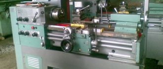
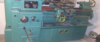
Photo of vertical drilling machine 2N118
Photo of vertical drilling machine 2n118
Photo of vertical drilling machine 2n118
Photo of vertical drilling machine 2n118
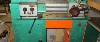
Photo of a vertical drilling machine 2n118. Feed and spindle control
Homemade machine
Today the price of machines is high, so for household needs you can make equipment yourself. The circuit diagram of such a device is quite simple. You will need four main components:
- Drill.
- Foundation slab.
- Vertical stand.
- Feeding mechanism.
First, you need a rough diagram of the future machine. Such a diagram is drawn with your own hands based on available materials. A thick furniture board can be used as a foundation slab. The vertical stand is made of thick plywood or chipboard. The base and vertical stand are fastened together with your own hands using self-tapping screws and corners.
After this, guides are made to move the drill. They are made from metal strips and screwed to the rack. The drill is secured to the block using steel clamps and rubber gaskets. The feed mechanism should lower and raise the drill. Its scheme is quite simple. You need to use a lever and a spring to stiffen the device.
Drilling devices today are presented in a wide range. Depending on your goals, you can choose the model you need or make it yourself.
The post-war rapid growth of industrial production in the USSR required an urgent expansion of the machine park. To prevent the outflow of currency abroad, domestic design bureaus began developing metal-cutting equipment. First, a basic model was produced, which was tested in real conditions. After this, the mechanism was improved. Such a modified unit is the 2N118 vertical drilling machine.
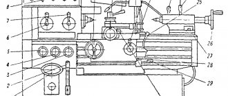
General view and controls of the drilling machine 2N118
Drilling machine controls 2n118
Specification of controls for drilling machine 2N118
- Light switch
- Cooling pump switch
- Input circuit breaker
- Feed mechanism control handle
- Mechanical feed button
- Feed shift knob
- Push-button station “Right”, “Left”, “Stop”
- Gear shift knob
- Drill head clamp handle
- Bolts for adjusting the wedge of the drill head
- Table Clamp Handle
- Bolts for adjusting the table wedge
- Table lift handle
- Drill head lifting mechanism roller square
- Cycle adjustment cams
- 3/4″ hole for connecting the machine to the electrical network
Table of contents
The 2N118 vertical drilling machine is designed to perform drilling work with a maximum drilling diameter of 18 mm. In addition, it is possible to perform other work: drilling, countersinking, reaming and threading.
The device of a vertical drilling machine
- Column, table, stove;
- Gearbox;
- Gearbox;
- Drill head;
- Machine spindle;
- Cooling system;
- Electrical equipment
Controls of a vertical drilling machine
- Local lighting
- Coolant pump
- Circuit breaker
- Feed mechanism control handle
- Turning on mechanical feed
- Feed switching
- Push button station
- Switching speeds
- Drill head clamp
- Drill head wedge adjustment bolts
- Table clamp
- Table wedge adjustment bolts
- Lifting the table
- Drill head lifting mechanism roller square
- Cycle adjustment cams
- Connecting the machine to the electrical network
Kinematic diagram of the vertical drilling machine 2N118
Electrical diagram of a vertical drilling machine
Vertical drilling machine gearbox
The gearbox of a vertical drilling machine, using two triple gear blocks 1 and 2, transmits nine different speeds to the spindle.
The gearbox mechanism consists of an electric motor located vertically and a gear transmission 5. Due to this transmission, it is possible to change the gear ratio, thereby changing the spindle speed range.
The output shaft of the gearbox 8 is made in the form of a sleeve with a splined hole that transmits torque to the machine spindle.
Speed switching is carried out using handle 10, which has three circumferential positions and three axial positions. The handle, through gears 11, 12 and rack 13, moves rods 14 and 15, which are connected to forks 16 and 17. The forks, in turn, switch movable blocks 1 and 2.
Feed box of vertical drilling machine
The feed box of a vertical drilling machine consists of three shafts mounted in a separate cast housing 1.
The feed box provides six feeds using a movable triple block 2 and a double block 3. The rotation of the feed box is transmitted from the gear wheel sitting on the spindle sleeve to gear 4.
The third shaft 5 transmits torque through a gear transmission to the ball clutch and the worm of the feed mechanism. The ball clutch is designed to turn off the feed when the required drilling depth is reached. It also serves as a safety device in case of overload in the feed force.
Speed switching is carried out using handle 13, which has two axial positions and three circular ones. The design of the feed and speed switching mechanisms is identical.
Lubrication of both the feed box and other mechanisms is carried out from gear pump 12.
Drill head of vertical drilling machine
The drilling head of a vertical drilling machine is a cast iron body into which the following machine components are installed:
- Machine speed box;
- Machine feed box;
- Headstock;
- Feed mechanism
The main part of the drilling head assembly is the feed mechanism, consisting of a worm gear 1, a horizontal shaft with a rack and pinion gear, a dial 3, a steering wheel 4, a cam clutch 5 and a ratchet clutch 6.
Kinematic diagram and equipment design
The supporting element of a vertical drilling machine of this model, equipped with a single-spindle head, is a massive box-shaped column mounted on a base plate. The headstock of the device is mounted in the upper part of the column, which can move along its guides. On the headstock there is the main electric motor of a vertical drilling machine, and on its lower part there is a spindle assembly with a working head in which the cutting tool is fixed.
Machine spindle head - front view
In the inner part of the spindle head there is a gearbox, which is responsible for adjusting the rotation speed of the drilling head, as well as ensuring the movement of the latter in the vertical direction. A rack and pinion mechanism, present in the kinematic diagram of the headstock, is responsible for raising and lowering the working head of the machine, and the body by which this mechanism is activated is a special steering wheel.
Before processing, the part is fixed on the surface of the work table, which also has the ability to move along the column guides. The height of its location, which is chosen depending on the dimensions of the workpiece, is changed using a rotating handle located on the front side of the unit.
Height-adjustable machine work table
The elements included in the kinematic diagram of the vertical drilling machine under consideration function as follows.
- The gearbox, due to the presence of several shafts and a number of gears in its design, allows you to adjust the speed of rotation of the drilling head in 9 steps. The output shaft of the gearbox, which is connected to the spindle assembly of the machine using a spline connection, is made in the form of a hollow sleeve. By reversing the drive motor, you can change the direction of rotation of the working head of the equipment, which is necessary if an internal thread is being cut in the workpiece.
- The spindle feed in the vertical direction, as mentioned above, is carried out by a rack mounted in the equipment quill and a gear engaged with it installed in the spindle head. The machine’s feed box, which contains several gears, allows you to adjust the vertical movement of the spindle assembly in 6 steps.
- Both the gearbox and the feedbox are installed in the spindle head of the vertical drilling machine, which can also move vertically along the column guides. A corresponding handle is responsible for this movement, carried out through a rack and worm connection.
- Vertical movement of the worktable, triggered by rotation of the corresponding handle, is provided by a conical and screw pair, which are equipped with the kinematic diagram of this structural element of the machine.
Kinematic diagram of a vertical drilling machine 2N118
The elements by which the operation of a vertical drilling machine of this model is controlled include:
- automatic type input switch;
- work area lighting switch;
- a switch for starting and stopping the coolant pump;
- handle responsible for controlling the feed mechanism;
- a button that turns on the feed mechanism;
- handle for selecting feed parameters;
- a push-button station on which the “Left”, “Right”, “Stop” buttons are mounted;
- a handle responsible for selecting the required rotation speed of the drilling head;
- a handle that provides clamping of the drill head;
- bolts with which the wedge of the drilling head is adjusted;
- bolts for adjusting the wedge of the work table;
- a handle used to clamp the desktop;
- a handle responsible for lifting the desktop along the column guides;
- a square end of the roller, through which the mechanism for lifting the drilling head is activated;
- cams, with the help of which the equipment operating cycles are configured;
- hole (3/4 inch) in which electrical contacts are located for connecting equipment to the power supply.
Specifics of machine components and controls
Elements of the electrical circuit of the device
The electrical circuit of the vertical drilling machine of the model in question includes the following elements:
- an electric motor that rotates the drill head;
- an electric pump responsible for supplying coolant to the processing zone;
- starting equipment and automation elements;
- selenium type electric rectifier;
- a step-down transformer from which the selenium rectifier is powered;
- elements included in the local lighting system.
Schematic diagram of the machine
The vertical drilling machine of this model uses a dynamic braking system, which functions as follows: a direct current generated by a selenium rectifier is supplied through the contacts of the brake starter to the three phases of the stator winding of the main electric motor. To ensure effective braking of the electric motor shaft when DC current is supplied to its stator, one of its windings is short-circuited in two phases. The braking of the electric motor shaft occurs at the moment when the corresponding button is pressed on the machine panel.
The electrical circuit of a vertical drilling machine works according to the following principle. When you press the “Right” button on the control panel (main operating mode), the first starter is started, which self-blocks with some of its contacts, and through others supplies power to the intermediate relay. The electric current through the intermediate relay, which is self-powered, can also be supplied to the second starter, which starts the rotation of the motor shaft in the opposite direction.
The electrical panel of the machine contains protection and automation elements, as well as an electrical circuit for dynamic spindle braking
The second starter, some of whose contacts are also self-locking, is turned on after pressing the “Left” button on the equipment control panel. Regardless of which direction the electric motor shaft rotates, when you press the “Stop” button, the corresponding starter is disconnected from the power supply and the braking starter, which is responsible for supplying direct current to the stator winding of the electric motor, is started.
The characteristics of this vertical drilling machine include the presence in its circuit of an automatic switch that protects the electric motor from overloads and short circuits. The machine also provides zero protection, which is possible thanks to the use of a magnetic starter coil in its circuit.
To ensure trouble-free operation and operator safety, it is necessary to ensure high-quality grounding of the vertical drilling machine, which must be carried out in accordance with all generally accepted requirements relating to production equipment.
Description of the design of the main components of the 2N118 drilling machine
Gearbox
The gearbox is designed to drive the machine spindle into rotation, as well as to change the frequency of its rotation (Fig. 7.5). The gearbox, through two gears 3 and 7, communicates to the spindle nine different rotation speed intervals. The gearbox shaft supports are placed in two plates: the top 5 and the bottom 8, which are tied together by three ties 4. The gearbox mechanisms are driven into rotation by a vertically located electric motor through a gear 6. The last gearbox shaft 2 is a hollow sleeve, splined hole which transmits rotation to the spindle. Gear 1 of the feed drive is attached to the same sleeve. The gearbox gears are switched from one handle, which has three positions around the circumference and three positions along the axis.
Gearbox
The feed box is a three-shaft mechanism mounted in a separate cast housing (Fig. 7.6). Six feeds are provided by gears 5 and 10.
The feed drive is carried out from a gear sitting on the spindle sleeve through gear 6. The third shaft of the feed box 9 is a hollow sleeve, inside of which passes shaft 8. This shaft, through clutch 7, transmits rotation to the worm of the feed mechanism through gear 1. Clutch 7 is used to turning on the mechanical feed when the specified processing depth is reached. In this case, the cam on the limb moves the rod vertically upward through a horizontal roller and, overcoming the resistance of the spring, disengages the clutch. Shaft 4, through pin 3, rotates the gear pump for lubrication.
The feed gears are switched by one handle, which has two axial positions and three circumferential positions. The handle is located on the front surface of the drilling head. The designs of the feed and speed switching mechanisms are identical.
The feedbox mechanisms are lubricated by gear pump 2, which also lubricates all other mechanisms. The feedbox mechanisms are assembled separately and the fully assembled unit is mounted in the drilling head.
Drill head
Drilling head of drilling machine 2n118
Drilling head of drilling machine 2n118. Download enlarged
The drilling head (Fig. 7.7) consists of a box-section cast iron in which all the main components of the machine are mounted: speed box, feed box, spindle and feed mechanism. The first three units are assembled separately and are only attached to the drilling head.
The feed mechanism, consisting of a worm gear, a horizontal shaft 3, a dial 7 with associated parts, a handle 10, a cam 14 and an overrunning clutch 16, is an integral part of the drilling head assembly.
The feed mechanism is driven from the feed box through a pair of gears and is designed to perform the following functions:
- manual approach of the tool to the workpiece;
- turning on the working feed;
- manual feed advance;
- turning off the working feed;
- manual spindle retraction;
- manual feed is usually used when cutting threads.
The operating principle of the feed mechanism is as follows: when the handle 10 rotates, the cam clutch 14 turns toward itself, which rotates the shaft 3 through the overrunning clutch 16. The spindle is manually approached.
When the tool approaches the workpiece, the torque on shaft 3 increases, which cannot be transmitted by the teeth of the cam clutch, and the hub moves to the left along the shaft until the ends of the cam clutch 14 and the overrunning clutch 16 are opposite each other.
During this period, the cam coupling 14 rotates freely relative to the shaft by 20°, the rotation is limited by a groove on the coupling and a pin 12.
On the hub of the overrunning clutch 16 sits a double-sided ratcheting disc 1, connected to it by pawls 9. When the hub is displaced, the teeth of the disc 1 engage with the teeth of the second disc 8, attached to the worm wheel 2.
Thus, the rotation from the worm is transmitted to the rack and pinion gear and mechanical feed occurs. With further rotation of the handle when the feed is turned on, the pawls 9, sitting in the hub of the overrunning clutch 16, slip over the teeth of the inner side of the disk 1 and thus the mechanical feed is manually advanced.
To manually turn off the feed, the handle is turned away from itself by 20° relative to the horizontal shaft 3, and the tooth of the coupling 14 stands against the cavity of the ratchet disk 1.
The hub, under the influence of an axial force arising from the inclination of the teeth of the disks 1 and 8, and a special spring 15, moves to the right and disengages the disks - the mechanical feed stops.
To carry out manual feed using the handle, it is necessary to turn off the mechanical feed with the steering wheel, and then move the cap 11 along the axis of the horizontal shaft to the right. In this case, pin 13 transmits torque directly from the cam clutch 14 to shaft 3.
A dial 7 is mounted on the left wall of the drilling head, which, when feeding the spindle, is driven into rotation through a pair of gears 4 and 6. The dial is intended for visually measuring the depth of processing and for adjusting the cams.
To visually measure the processing depth, the tool is manually brought into contact with the workpiece being processed and the dial is set to the zero position using pins 5 with the left hand. The depth of processing is measured on a scale on the cylindrical surface of the limb.
Machine spindle
Drilling machine spindle 2n118
The machine spindle (Fig. 7.8) is mounted in two ball bearings 7 and 4. The axial feed force is perceived by the thrust bearing 6. The bearings are located in the spindle sleeve 5, which, using a rack and pinion transmission, can move along the axis. The spindle bearings are adjusted by nut 3 located above the upper spindle support.
The spindle bearings are lubricated with a wick from the cavity of the sleeve 2. A ring 8 is loosely mounted on the end of the spindle, the end of which includes a pin 9. A special cap 1 is used to prevent it from falling out.
When changing a tool, it is necessary to sharply move the handle of the feed mechanism to send the spindle to the upper position, while the loosely seated ring 8 will rest against the head body, and the pin 9, hitting the upper end of the tool, will knock it out.
Drilling machine spindle bearings 2n118
The spindle of the 2n118 machine is mounted on 3 bearings:
- 7. Lower bearing No. 7000105 GOST 8338-57 open-type single-row radial ball bearing, accuracy class A(4), size 17x40x13.5 mm
- 6. Bearing No. 8205 GOST 6874-54 thrust ball, accuracy class P(6), 25x47x15
- 4. Upper bearing No. 7000105 GOST8338-75 open-type radial ball single-row bearing, accuracy class B(5), 25x47x8
Modern bearing accuracy class designations
Technical characteristics of bearing No. 7000105
Bearing 7000105 is an open type single row deep groove ball bearing belonging to the extra light diameter series and the narrow width series. Designed to withstand radial loads at high rotation speeds.
In Russia it is produced at two enterprises - in Samara at SPZ-4 and in Vologda at 23 GPP. The latter plant produces this bearing of a higher class, from good materials, which, of course, affects its cost.
This bearing is used in domestic trolleybuses (door opening mechanism) and tram cars.
The imported bearing of this type is number 16005. They come standard with a stamped steel cage, but can also be supplied with machined brass or polyamide cages. For high operating temperatures, it is recommended to use polyamide or glass-filled polyetheretherketone separators. Imported bearings of this series are usually supplied as a closed type and do not require maintenance.
Dimensions and characteristics of bearing 7000105 (16005)
- Inner diameter (d): – 25 mm;
- Outer diameter (D): – 47 mm;
- Width (H): – 8 mm;
- Weight: – 0.08 kg;
- Number of balls in the bearing: - 11 mm;
- Ball diameter: - 5.556 pcs;
- Dynamic load capacity: - 7.6 kN;
- Static load capacity: - 4 kN;
- Maximum rated speed: - 17000 rpm.
Setting up and setting up a drilling machine 2n118
Setting up the machine for normal operation consists of installing the table and drilling head in the positions required for operation, clamping them on the column and setting the required speeds and spindle feeds.
In addition to normal work with mechanical feed, the machine can work with the following cycles:
- with manual spindle feed;
- with switching off the feed at a given depth;
- with automatic reversal of the spindle at a given depth when cutting threads.
Setting up the machine to operate with manual feed
To turn on the manual feed, the cap with the adjustment located in the center of the cross steering wheel should be pressed all the way away.
Setting up the machine for operation with turning off the feed at a given depth
To set up the machine to operate with the feed turned off at a given depth, you must:
- install the tool in the spindle and the part on the machine table;
- lower the spindle until the tool stops in the part;
- set the dial on the drilling head so that opposite the pointer there is a number corresponding to the depth of processing, taking into account the cone of the tool;
- secure the cam with the letter “P” so that its right end coincides with the corresponding mark on the dial.
After turning on the spindle rotation and feed, processing of the part will begin; When the desired depth is reached, the feed stops, but the spindle will continue to rotate.
Setting up the machine for automatic thread cutting
To set up a machine for thread cutting with spindle reversal at a certain depth, you must:
- install the chuck with a tap in the spindle, the part on the machine table;
- lower the spindle until the tool stops in the part;
- set the dial on the drilling head so that opposite the pointer there is a number corresponding to the processing depth;
- fasten the cam with the letter “P” so that its right end coincides with the corresponding mark on the dial.
After turning on the spindle, the tap is manually inserted into the hole; after 2-3 turns, there is no need for manual feed; After reaching the specified depth, the spindle is automatically reversed and the tap comes out of the hole.
In order for the spindle to rotate to the right again, you must press the “Right” control button.
Electrical equipment and electrical circuit of the drilling machine 2N118
Electrical diagram of drilling machine 2n118
The electrical equipment of the machine contains:
- spindle rotation electric motor 1M;
- electric cooling pump 2M;
- start-up and automation equipment;
- selenium rectifier SV;
- local lighting.
Control of drilling machine 2N118
The following controls are installed on the machine:
- control buttons - “Left”, “Right” and “Stop”;
- introductory machine;
- manual starter for turning on the cooling pump with “Start” and “Stop” buttons.
Braking the spindle of the machine 2N118
The machine uses a dynamic braking circuit with direct current supplied to three phases of the stator winding through the contacts of the SC brake starter from a selenium rectifier SV, which is powered by a step-down transformer TBS2-01. Simultaneously with the supply of DC current during braking, the stator winding is short-circuited in two phases for better braking efficiency. Braking occurs only when the ZKU or 2VK button is pressed.
Operation of the electrical circuit of the 2N118 machine
By pressing the 1KU “Right” button, the K1 starter is turned on, which is self-blocking with block contacts 6-7, and with contacts 4-16 it turns on the intermediate relay RP, which with its contacts 4-16 will become self-powered, and with contacts 14-9 it prepares the switching on of the K2 starter, if During operation on the machine, spindle rotation is reversed by pressing 1VK.
By pressing the 2KU “Left” button, the K2 starter is turned on, which is self-blocking with block contacts 4-9.
Whenever the spindle rotates to the right, left, pressing the “Stop” button, braking is performed, and K1 and RP are turned off if there was a rotation to the right, or K2 if the rotation was to the left. Through contacts 13, 17, 18, the short-circuit braking starter will turn on, which supplies direct current to the stator winding of the electric motor, and the engine will brake.
Electrical equipment of tabletop drilling machine 2M112
- The electrical equipment of the 2M112 drilling machine is designed for power supply from a three-phase alternating current network with a voltage of 380V, 50 Hz.
- If necessary, the 2M112 machine with electrical equipment can be made upon special order for a voltage of 220V, 50 Hz.
- The starting and protective equipment is mounted in the plate of the 2M112 table-top drilling machine.
Protection of tabletop drilling machine 2M112
- The electrical equipment of the 2M112 machine is protected from short circuits and overloads by a single-pole circuit breaker.
- To prevent self-starting of electric motors, zero protection is applied using contacts of magnetic starters K1 and K2.
Schematic diagram of the tabletop drilling machine 2M112
Specification of purchased electrical equipment
| Designation according to the diagram | Name | Qty |
| QFI | Automatic switch VA47-2916A | 1 |
| KM1, KM2 | Magnetic contactor KMI 11210 | 2 |
| M | Electric motor: | 1 |
| SB1 | Button KE021 red. | 1 |
| SB2 | Button KE011 black | 1 |
| SB3 | Button KE011 black | 1 |
Instructions for connecting and servicing electrical equipment of the 2M112 drilling machine
- The 2M112 tabletop drilling machine must be connected to the general grounding system of the workshop using a special bolt located on the machine plate. Grounding of the machine and operation of its electrical equipment must be carried out in accordance with the requirements of the “Rules for technical operation and safety of maintenance of electrical installations of industrial enterprises.”
- When servicing, adjusting and repairing the electrical equipment of the 2M112 machine, you must follow the established safety rules for electrical installation work. Access to the contact parts of electrical machines and devices is permitted only after the machine is disconnected from the network by a circuit breaker.
- It is recommended to first do a test run of the 2M112 drilling machine at idle speed at all speeds sequentially, starting with the lowest spindle speed. During the first period after starting the machine, it is not recommended to work at maximum spindle speed.
- To ensure long-term and trouble-free operation of the 2M112 drilling machine, it is necessary to regularly:
- clean the electric motor, starting and protective equipment from dust,
- clean contacts from carbon deposits,
- tighten connections of wires to equipment as necessary.
Compliance with the above rules will ensure long-term uninterrupted operation of the 2M112 drilling machine and the safety of operating personnel
Initial launch of tabletop drilling machine 2M112
- Before the initial start-up of the 2M112 machine, all instructions set out in the sections “Machine Electrical Equipment” and “Lubrication System” related to the initial start-up must be followed.
- Then a test run is done at idle at all speeds sequentially, starting with the lowest spindle speed. After making sure that all the mechanisms of the machine are working properly, you can begin to operate it.
- During the first period after launching the 2M112 tabletop drilling machine, it is not recommended to work at maximum spindle speed.